EP1916068A2 - Prise de force pour cloueur sans fil - Google Patents
Prise de force pour cloueur sans fil Download PDFInfo
- Publication number
- EP1916068A2 EP1916068A2 EP07117710A EP07117710A EP1916068A2 EP 1916068 A2 EP1916068 A2 EP 1916068A2 EP 07117710 A EP07117710 A EP 07117710A EP 07117710 A EP07117710 A EP 07117710A EP 1916068 A2 EP1916068 A2 EP 1916068A2
- Authority
- EP
- European Patent Office
- Prior art keywords
- arm
- driver
- flywheel
- assembly
- actuator
- Prior art date
- Legal status (The legal status is an assumption and is not a legal conclusion. Google has not performed a legal analysis and makes no representation as to the accuracy of the status listed.)
- Granted
Links
Images


















Classifications
-
- B—PERFORMING OPERATIONS; TRANSPORTING
- B25—HAND TOOLS; PORTABLE POWER-DRIVEN TOOLS; MANIPULATORS
- B25C—HAND-HELD NAILING OR STAPLING TOOLS; MANUALLY OPERATED PORTABLE STAPLING TOOLS
- B25C1/00—Hand-held nailing tools; Nail feeding devices
- B25C1/06—Hand-held nailing tools; Nail feeding devices operated by electric power
-
- B—PERFORMING OPERATIONS; TRANSPORTING
- B25—HAND TOOLS; PORTABLE POWER-DRIVEN TOOLS; MANIPULATORS
- B25C—HAND-HELD NAILING OR STAPLING TOOLS; MANUALLY OPERATED PORTABLE STAPLING TOOLS
- B25C1/00—Hand-held nailing tools; Nail feeding devices
- B25C1/008—Safety devices
Definitions
- the backbone 14 may be a structural element upon which the drive motor assembly 18, the control unit 20, the nosepiece assembly 22, and/or the magazine assembly 24 may be fully or partially mounted.
- the drive motor assembly 18 may be of any desired configuration, but in the example provided, includes a power source 30, a driver 32, a follower assembly 34, and a return mechanism 36.
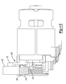
- the power source 30 includes a motor 40, a flywheel 42, and an actuator 44.
- the motor mount 60 may include an arcuate surface 80 having features, such as a plurality of tabs 82, that abut the motor 40.
- the tabs 82 support the opposite longitudinal ends of the motor 40 and serve to space a flux ring that is disposed about the middle of the motor 40 apart from the motor mount 60.
- the motor mount 60 may be configured such that a continuous full sweeping arc of material is disposed at both ends of the motor 40 for support, while the flux ring is elevated above the motor mount 60. As motion of motor 40 against the backbone 14 may cause wear, rotational constraint of the motor 40 relative to the backbone 14 may be obtained through the abutment of the transmission plate 256 against a feature on the backbone 14.
- the motor 40 may be a conventional electric motor having an output shaft (not specifically shown) with a pulley 254 coupled thereto for driving the flywheel assembly 250.
- the motor 40 may be part of a motor assembly that may include a transmission plate 256 and a belt-tensioning device 258.
- the hub 320 may be formed from a hardened material such that the ends of the hub 320 may form wear-resistant thrust surfaces.
- the hub 320 includes a through-hole 330 that is sized to engage the flywheel shaft 200.
- the through-hole 330 includes a threaded portion and a counterbored portion that is somewhat larger in diameter than the threaded portion.
- the wear-resistant coating 390 may be formed of a) tungsten carbide and applied via a high-velocity oxy-fuel process, b) tantalum tungsten carbide and applied via an electro-spark alloying process, c) electroless nickel and applied via a chemical bath, or d) industrial hard chrome and applied via electroplating.
- first and second support bearings 302 and 304 may be pressed into, adhesively coupled to or otherwise installed to the first and second backbone portions 14a and 14b, respectively in the flywheel bore 194.
- the flywheel 42 may be placed into the flywheel cavity 192 in the backbone 14 such that the through-hole 330 in the hub 320 is aligned to the flywheel bore 194.
- the flywheel shaft 200 is inserted into the flywheel bore 194 and installed to the flywheel 42 such that the threaded portion 410 is threadably engaged to the threaded portion of the through-hole 330 in the hub 320 of the flywheel 42, the central portion 400 is supported by the first support bearing 302, the portion of the central portion 400 between the first support bearing 302 and the threaded portion 410 of the flywheel shaft 200 is received into the counterbored portion of the hub 320 of the flywheel 42, and the necked-down portion 412 is supported by the second support bearing 304.
- the first and second support bearings 302 and 304 engage the flywheel shaft 200 in a slip fit manner, which permits the flywheel shaft 200 to be slidably inserted into the flywheel bore 194.
- the flywheel shaft 200 may be rotated relative to the flywheel 42 to draw the flywheel 42 into abutment with the first support bearing 302 such that the inner race 302a of the first support bearing 302 is clamped between the flywheel 42 and a shoulder 420 between the first end portion 402 and the central portion 400.
- an assembly feature 422 such as a non-circular hole (e.g., hex, square, Torx® shaped) or a slot may be formed in or a protrusion may extend from either the flywheel pulley 300 or the first end portion 402.
- the assembly feature 422 is configured to be engaged by a tool, such as an Allen wrench, an open end wrench or a socket wrench, to permit the flywheel shaft 200 to be rotated relative to the flywheel 42.
- the motor 40, belt 280, flywheel pulley 300 and flywheel 42 may be configured so that the surface speed of the exterior surface 350 of the flywheel 42 may attain a velocity of about 86 ft/sec to 92 ft/sec.
- the flywheel pulley 300 has been described as being a discrete component, those skilled in the art will appreciate that it may be otherwise formed.
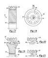
- the flywheel shaft 200 may be formed such that the first end portion 402 includes a plurality of retaining features 450, such as teeth or splines, that may be formed in a knurling process, for example, as is shown in Figure 22.
- the flywheel pulley 300 may be insert molded to the flywheel shaft 200.
- the tooling that is employed to form the flywheel pulley 300 may be configured to locate on the outer diameters of the central portion 400 or the second end portion 404, which may be ground concentrically about the rotational axis of the flywheel shaft 200. Accordingly, the flywheel pulley 300 may be inexpensively attached to the flywheel shaft 200 in a permanent manner without introducing significant runout or other tolerance stack-up.
- the upper driver member 500 may include a body 510 and a pair of projections 512 that extend from the opposite lateral sides of the body 510.
- the body 510 may include a driver profile 520, a cam profile 522, an abutment 524, a blade recess 526, a blade aperture 528, and a retainer aperture 530.
- the driver profile 520 is configured in a manner that is complementary to the exterior surface 350 of the outer rim 322 of the flywheel 42.
- the driver profile 520 includes a plurality of longitudinally extending V-shaped teeth 534 that cooperate to form a plurality of valleys 536 and peaks 538.
- the valleys 536 may terminate at a slot 540 having spaced apart wall members 542 rather than at a sharp corner.
- the slots 366 and 540 in the outer rim 322 and the body 510, respectively, provide a space into which the V-shaped teeth 534 and 360, respectively, may extend as the exterior surface 350 and/or the driver profile 520 wear to thereby ensure contact between the exterior surface 350 and the driver profile 520 along a substantial portion of the V-shaped teeth 360 and 534, rather than point contact at one or more locations where the peaks 362 and 538 contact the valleys 536 and 364, respectively.
- a coating 550 may be applied to the body 510 at one or more locations, such as over the driver profile 520 and the cam profile 522.
- the coating may be a type of carbide and may be applied via a plasma spray, for example.
- the cam profile 522 may be formed on a side of the body 510 opposite the driver profile 520 and may include a first cam portion 560 and a second cam portion 562 and a pair of rails 564 that may extend between the first and second cam portions 560 and 562.
- the abutment 524 may be formed on the body 510 on a side opposite the side from which the driver blade 502 extends and may include an arcuate end surface 570 that slopes away from the driver profile 520. The cam profile 522 and the abutment 524 are discussed in greater detail, below.
- the blade recess 526 may be a longitudinally extending cavity that may be disposed between the rails 564 of the cam profile 522.
- the blade recess 526 may define an engagement structure 590 for engaging the driver blade 502 and first and second platforms 592 and 594, that may be located on opposite sides of the engagement structure 590.
- the engagement structure 590 includes a plurality of teeth 600 that cooperate to define a serpentine-shaped channel 602, having a flat bottom 606 that may be co-planar with the first platform 592.
- the first platform 592 may begin at a point that is within the blade recess 526 proximate the blade aperture 528 and may extend to the lower surface 612 of the body 510, while the second platform 594 is positioned proximate the retainer aperture 530.
- the blade aperture 528 is a hole that extends longitudinally through a portion of the body 510 of the driver 32 and intersects the blade recess 526.
- the blade aperture 528 may include fillet radii 610 (Fig. 26) so that a sharp corner is not formed at the point where the blade aperture 528 meets the exterior lower surface 612 of the body 510.
- the retainer aperture 530 may extend through the body 510 of the driver 32 in a direction that may be generally perpendicular to the longitudinal axis of the driver 32.
- the retainer aperture 530 is a slot having an abutting edge 620 that is generally parallel to the rails 564.
- the projections 512 may be employed both as return anchors 630, i.e., points at which the driver 32 is coupled to the return mechanism 36 (Fig. 2), and as bumper tabs 632 that are used to stop downward movement of the driver 32 after a fastener has been installed to a workpiece.
- Each return anchor 630 may be formed into portions of an associated projection 512 that extends generally parallel to the longitudinal axis of the driver 32.
- the return anchor 630 may include a top flange 650, a rear wall 652, a pair of opposite side walls 654 and a front flange 656.
- the top flange 650 may extend between the side walls 654 and defines a cord opening 660.
- the rear wall 652 which may intersect the top flange 650, cooperates with the top flange 650, the side walls 654 and the front flange 656 to define an anchor cavity 662.
- the rear wall 652 is generally parallel to the longitudinal axis of the driver 32 at a location that is across from the front flange 656 and is arcuately shaped at a location below the front flange 656.
- the side walls 654 may be coupled to the rear wall 652 and the front flange 656 and may include an anchor recess 664, which may extend completely through the side wall 654.
- the bumper tabs 632 define a contact surfaces 670 that may be cylindrically shaped and which may be arranged about axes that are generally perpendicular to the longitudinal axis of the driver 32 and generally parallel one another and disposed on opposite lateral sides of the driver profile 520.
- the blade portion 692 extends downwardly from the retaining portion 690 and through the blade aperture 528 in the body 510.
- the opposite end of the driver blade 502 may include an end portion 720 that is tapered in a conventional manner (e.g., on the side against which the fasteners in the magazine assembly 24 are fed) and on its laterally opposite sides.
- the sloped surface of the engagement member 732 of the retainer 504 is abutted against the matching sloped surface of the engagement tab 710, which serves to wedge the engagement tab 710 against the second platform 594.
- the tab 734 may be deformed (e.g., bent over and into contact with the body 510 or twisted) so as to inhibit the retainer 504 from withdrawing from the retainer aperture 530.
- a structural gap filling material 740 such as a metal, a plastic or an epoxy, may be applied to the engagement structure 590 and the corresponding engagement structure 700 to inhibit micro-motion therebetween.
- the structural gap filling material 740 comprises an epoxy that is disposed between the teeth 600 and 702.
- suitable metals for the structural gap filling material 740 include zinc and brass.
- the magazine assembly 24 slopes upwardly with increasing distance from the nosepiece assembly 22, but is maintained in a plane that includes the axis 118 as shown in Figure 1 as well as the centerline of the housing assembly 12. In some situations, however, the slope of the magazine assembly 24 may bring it into contact with another portion of the fastening tool 10, such as the handle of the housing assembly 12. In such situations, it is desirable that the driver blade 502 (Fig. 23) be arranged generally perpendicular to the axis along which fasteners F are fed from the magazine assembly 24.
- One solution may be to rotate the orientation of drive motor assembly 18 and nosepiece assembly 22 so as to conform to the axis along which fasteners F are fed from the magazine assembly 24. This solution, however, may not be implementable, as it may not be practical to rotate the drive motor assembly 18 and/or the appearance of the fastening tool 10 may not be desirable when its nosepiece assembly 22 has been rotated into a position that is different from that which is illustrated.
- the nosepiece 22a of the nosepiece assembly 22 may be coupled to the housing assembly 12 and backbone 14 (Fig. 2) as described herein, but may be configured to receive fasteners F from the magazine assembly 24 along the axis along which the fasteners F are fed.
- This arrangement is schematically illustrated in Figure 29.
- the drive motor assembly 18 (Fig. 1), however, may be rotated about the axis 118 (Fig. 1) and the centerline of the housing assembly 12 to align the driver blade 502 to the nosepiece 22a.
- the backbone 14 may optionally carry a skid plate 750 and/or a skid roller 752.
- the skid plate 750 is coupled to the backbone 14 on a side of the flywheel assembly 250 opposite the skid roller 752.
- the skid plate 750 may be formed of a wear resistant material, such as carbide, and is configured to protect the backbone 14 against injurious contact with the body 510 (Fig. 23) of the driver 32 (Fig. 23) at a location between the flywheel 42 and the nosepiece assembly 22 (Fig. 1).
- the driver profile 520 (Fig. 23) of the driver profile 520 (Fig. 23).
- an upper skid plate (not shown) may be substituted for the skid roller 752.
- the rollers 754 of the skid roller 752 engage a relatively large surface area of the driver profile 520 (Fig. 23) with relatively lower friction than an upper skid plate.
- the actuator 44 may be any appropriate type of actuator and may be configured to selectively provide linear and/or rotary motion.
- the actuator 44 is a linear actuator and may be a solenoid 810 as shown in Figure 41.
- the solenoid 810 may be housed in the bore 150 of the actuator mount 62 in the backbone 14.
- the solenoid 810 may include a pair of arms 812 that are received into the channels 152 that are formed in the actuator mount 62. Threaded fasteners 814 may be received through the slotted apertures 816 (Fig. 3) in the actuator mount 62 and threadably engaged to the arms 812 to thereby fixedly but removably and adjustably couple the solenoid 810 to the backbone 14.
- the solenoid 810 may include a plunger 820 that is biased by a spring 822 into an extended position.
- the plunger 820 may have a shoulder 824, a neck 826 and a head 828.
- the ground plate 170 may be disposed in the clutch mount 64 and fixedly coupled to the backbone 14 as described above.
- the ground plate 170 may include a set of ways 830, which may extend generally parallel to the axis 158 of the bore 150, and a plurality of inwardly tapered engagement surfaces 836 that may be disposed on the opposite sides of the ways 830 and which extend generally parallel to the ways 830.
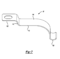
- the activation arm 806 may include an arm structure 850, a cam follower 852, an arm pivot pin 854, a follower pivot pin 856 and a spring 858.
- the arm structure 850 may include a pair of arm members 870 that are spaced apart by a pair of laterally extending central members 872 that is disposed between the arm members 870.
- Each arm member 870 may be generally L-shaped, having a base 880 and a leg 882 that may be disposed generally perpendicular to the base 880.
- Each base 880 may define a pivot aperture 890, which is configured to receive the arm pivot pin 854 therethrough, a coupling aperture 892, which is configured to receive the follower pivot pin 856 therethrough, a rotational stop 894, which limits an amount by which the roller assembly 808 may rotate relative to the activation arm 806 in a given rotational direction, while each leg 882 may define a follower aperture 898 that is configured to receive the cam follower 852 therein.
- the cam follower 852 may be a pin or roller that is rotatably supported by the legs 882.
- the cam follower 852 is a roller with ends that are disposed in the follower apertures 898 in a slip-fit manner.
- the arm pivot pin 854 may be disposed through the follower pivot 68 and the pivot apertures 890 in the bases 880 to pivotably couple the activation arm 806 to the backbone 14.
- the activation arm 806 is disposed between the arms 204 that form the follower pivot 68 and the arm pivot pin 854 is inserted through the bushings 206 and the pivot apertures 890.
- the follower pivot pin 856 may extend through the coupling apertures 892 and pivotably couple the roller assembly 808 to the activation arm 806.
- the spring 858 may bias the roller assembly 808 in a predetermined rotational direction.
- the spring 858 includes a pair of leaf springs, whose ends are abutted against the laterally extending central members 872, which may include features, such as a pair of spaced apart legs 900, that are employed to maintain the leaf springs in a desired position.
- the leaf springs may be configured in any desired manner, but are approximately diamond-shaped in the example provided so that stress levels within the leaf springs are fairly uniform over their entire length.
- the arm structure 850 may be a unitarily formed stamping which may be made in a progressive die, a multislide or a fourslide, for example, and may thereafter heat treated.
- the sheet material from which the arm structure 850 may be formed may be relatively thin, residual stresses as well as the heat treating process may distort the configuration of the arm members 870, which would necessitate post-heat treatment secondary processes (e.g., straightening, grinding).
- post-heat treatment secondary processes e.g., straightening, grinding.
- one or more slots 910 may be formed in the arm members 870 as shown in Figure 36 to receive a key 912 (which is shown in Figure 38) therethrough prior to the heat treatment operation.
- One or more sets of grooves 916 may be formed in the key 912 so as to permit the key 912 to engage the arm members 870 as is schematically illustrated in Figure 37.
- two sets of grooves 916 are employed wherein the grooves 916 are spaced apart on the key 912 by a distance that corresponds to a desired distance between the arm members 870.
- Rotation of the key 912 in the slots 910 after the grooves 916 have been aligned to the arm members 870 locks the key 912 between the arm members 870.
- the key 912 thus becomes a structural member that resists deformation of the arm members 870.
- one or more keys 912 may be installed to the arm members 870 prior to the heat treatment of the activation arm 806 to thereby inhibit deformation of the arm members 870 relative to one another prior to and during the heat treatment of the activation arm 806. Moreover, the keys 912 may be easily removed from the activation arm 806 after heat treatment by rotation of the key 912 in the slot 910 and re-used or discarded as appropriate.
- the key 912 or keys 912 may be formed by the same tooling that is employed to form the arm structure 850. More specifically, the key 912 or keys 912 may be formed in areas inside or around the blank from which the arm structure 850 is formed that would otherwise be designated as scrap.
- the roller assembly 808 may include a roller cage 920, a pair of eccentrics 922, an axle 924, a follower 50, and a biasing mechanism 928 for biasing the eccentrics 922 in a predetermined direction.
- the roller cage 920 may include a pair of auxiliary arms 930 and a reaction arm 932 that is disposed between the auxiliary arms 930 and which may be configured with an cylindrically-shaped contact surface 934 that is employed to contact the spring 858.
- Each auxiliary arm 930 may include an axle aperture 940, a range limit slot 942, which is concentric with the axle aperture 940, a pin aperture 944, an assembly notch 946, and a stop aperture 948, which is configured to receive the rotational stops 894 that are formed on the arm members 870.
- the roller cage may be unitarily formed stamping which may be made in a progressive die, a multislide or a fourslide, for example, and may thereafter heat treated.
- one or more slots 952 which are similar to the slots 910 (Fig. 36) that are formed in the arm structure 850, and keys, which that are similar to the keys 912 (Fig. 38) that are described above, may be employed to prevent or resist warping, bending or other deformation of the auxiliary arms 930 relative to one another prior to and during heat treatment of the roller cage 920.
- each of the eccentrics 922 may be a plate-like structure that includes first and second bosses 970 and 972, which extend from a first side, and an axle stub 974 and a stop member 976 that are disposed on a side opposite the first and second bosses 970 and 972.
- the axle stub 974 is configured to extend through the axle aperture 940 (Fig. 39) in a corresponding one of the auxiliary arms 930 and the stop member 976 is configured to extend into the range limit slot 942 to limit an amount by which the eccentric 922 may be rotated about the axle stub 974.
- An axle aperture 980 may be formed into the first boss 970 and configured to receive the axle 924 therein. In some situations, it may not be desirable to permit the axle 924 to rotate within the axle aperture 980.
- a pair of flats 982 are formed on the axle 924, which gives the ends of the axle 924 a cross-section that is somewhat D-shaped.
- the axle aperture 980 in this example is formed with a corresponding shape (i.e., the axle aperture 980 is also D-shaped), which permits the axle 924 to be slidingly inserted into the axle aperture 980 but which inhibits rotation of the axle 924 within the axle aperture 980.
- the second boss 972 may be spaced apart from the first boss 970 and may include a pin portion 986.
- the pin portion 986 may be a discrete member that is fixedly coupled (e.g., press fit) to the eccentric 922.
- the follower 50 which is a roller in the example provided, is rotatably disposed on the axle 924.
- bearings such as roller bearings, may be employed to rotatably support the follower 50 on the axle 924.
- the biasing mechanism 928 may include a yoke 1000, a spacer 1002 and a spring 1004.
- the yoke 1000 may include a generally hollow cross-bar portion 1010 and a transverse member 1012 upon which the spring 1004 is mounted.
- the cross-bar portion 1010 may have an aperture 1016 formed therein for receiving the pin portions 986 of the second boss 972 of each eccentric 922.
- the spacer 1002 may include a body 1020 having a pair of flange members 1022 and 1024, a coupling yoke 1026, a cantilevered engagement member 1028.
- a counterbore 1030 may be formed into the body 1020 for receiving the spring and the transverse member 1012 of the yoke 1000.
- the flange members 1022 and 1024 extend outwardly from the opposite lateral sides of the body 1020 over the auxiliary arms 930 that abut the body 1020.
- the flange members 1022 and 1024 cooperate to guide the spacer 1002 on the opposite surfaces of the auxiliary arms 930 when the spacer 1002 is installed to the auxiliary arms 930, as well as inhibit rotation of the spacer 1002 relative to the roller cage 920 about the follower pivot pin 856.
- the engagement member 1028 may be engaged to the assembly notches 946 (Fig. 39) that are formed in the auxiliary arms 930.
- the coupling yoke 1026 includes an aperture 1036 formed therethrough which is configured to receive the follower pivot pin 856 to thereby pivotably couple the roller assembly 808 to the activation arm 806 as well as inhibit translation of the spacer 1002 relative to the roller cage 920.
- the roller assembly 808 may be assembled as follows: a) the follower 50 is installed over the axle 924; b) a first one of the eccentrics 922 is installed to the axle 924 such that the axle 924 is disposed in the axle aperture 980; c) the yoke 1000 is installed to the pin portion 986 of the first one of the eccentrics 922; d) the other one of the eccentrics 922 is installed to the axle 924 and the yoke 1000; e) the subassembly (i.e., eccentrics 922, axle 924, follower 50 and yoke 1000) is installed to the roller cage 920 such that the axle stubs 974 are located in the axle apertures 940 and the stop members 976 are disposed in the range limit slots 942; f) the spring 1004 may be fitted over the transverse member 1012; g) the spacer 1002 may be aligne
- the return mechanism 36 may include a housing 1050 and one or more return cords 1052.
- the housing 1050 may include a pair of housing shells 1050a and 1050b that cooperate to define a pair of spring cavities 1056 that are generally parallel one another.
- the housing shell 1050a may include a set of attachment features 1058 that permit the housing shell 1050a to be fixedly coupled to the backbone 14.
- the set of attachment features 1058 include a pair of legs 1060 and a pair of bayonets 1062.
- the legs 1060 are coupled to a first end of the housing shell 1050a and extend outwardly therefrom in a direction that is generally parallel to the spring cavities 1056.
- the bayonets 1062 are coupled to an end of the housing shell 1050a opposite the legs 1060 and extend therefrom in a direction that is generally perpendicular to the legs 1060.
- the legs 1060 and bayonets 1062 are configured to be received under laterally extending tabs 1066 and 1068, respectively, that are formed on the backbone 14. More specifically, the legs 1060 may be installed to the backbone 14 under the laterally extending tabs 1066 and thereafter the housing 1050 may be rotated to urge the bayonets 1062 into engagement with the laterally extending tabs 1068.
- the laterally extending tabs 1068 may include an arcuately shaped surface 1070, which may cooperate with the bayonets 1062 to cause the bayonets 1062 to resiliently deflect toward the legs 1060 as the housing 1050 is being rotated toward the backbone 14.
- each return cord 1052 may include a cord portion 1080, a spring 1082 and a keeper 1084.
- the cord portion 1080 may be a resilient cord that may be formed of a suitable rubber or thermoplastic elastomer and may include a first retaining member 1090, which may be configured to releasably engage the return anchors 630, a second retaining member 1092, which may be configured to be engaged by the keeper 1084, and a cord member 1094 that is disposed between the first and second retaining members 1090 and 1092.
- the second retaining member 1092 may include a conical face 2000 and a spherical end 2002.
- the first retaining member 1090 may include a body 2006 and a pair of tab members 2008 that extend from the opposite sides of the body 2006.
- the first retaining member 1090 may be configured to couple the cord portion 1080 to the driver 32 (Fig. 23).
- the body 2006 may be received into the anchor cavity 662 (Fig. 25) such that the tab members 2008 extend into the anchor recesses 664 (Fig. 23) and the cord member 1094 extends outwardly of the cord opening 660 (Fig. 27) in the top flange 650 (Fig. 27).
- the arcuate portion of the rear wall 652 (Fig. 25) is configured to guide the first retaining member 1090 into the anchor cavity 662 (Fig. 25) and the tab members 2008 extend through the side walls 654 (Fig. 23) when the first retaining member 1090 is engaged to the return anchor 630 (Fig. 23).
- the cord member 1094 may have a substantially uniform cross-sectional area over its entire length.
- the cord member 1094 tapers outwardly (i.e., is bigger in diameter) at its opposite ends where it is coupled to the first and second retaining members 1090 and 1092.
- Fillet radii 2012 are also employed at the locations at which the cord member 1094 is coupled to the first and second retaining members 1090 and 1092.
- the spring 1082 may be a conventional compression spring and may include a plurality of dead coils (not specifically shown) on each of its ends.
- the keeper 1084 is employed to transmit loads between the cord member 1094 and the spring 1082 and as such, may include first and second contact surfaces 2016 and 2018, respectively, for engaging the second retaining member 1092 and the spring 1082, respectively.
- the keeper 1084 is a sleeve having a first portion 2020, a smaller diameter second portion 2022 and a longitudinally extending slot 2024 into which the cord member 1094 may be received.
- the first contact surface 2016 may be formed onto the first portion 2020 and may have a conically-shaped surface that is configured to matingly engage the conical face 2000 of the second retaining member 1092.
- the second portion 2022 may be formed such that its interior surface 2024 tapers outwardly toward it lower end.
- a shoulder that is formed at the intersection of the first portion 2020 and the second portion 2022 may define the second contact surface 2018, which is abutted against an end of the spring 1082.
- the return cord 1052 is installed to the spring cavity 1056 in the housing 1050. More specifically, the lower end of the spring 1082 is abutted against the housing 1050, while the spherical end 2002 of the second retaining member 1092 abuts an opposite end of the housing 1050. Configuration of the second retaining member 1092 in this manner (i.e., in abutment with the housing 1050) permits the second retaining member 1092 to provide shock resistance so that shock loads that are transmitted to the keeper 1084 and the spring 1082 may be minimized or eliminated.
- the two-component configuration of the return cord 1052 is highly advantageous in that the strengths of each component offset the weakness of the other.
- the deceleration that is associated with the downstroke of the driver 32 i.e., from abut 65 f.p.s. to about 0 f.p.s. in the example provided
- the relatively long overall length of travel of the driver could be detrimental to the life of a rubber or rubber-like cord.
- Incorporation of a coil spring 1082 into the return cord 1052 prevents the cord member 1094 from overstretching, whereas the cord member 1094 prevents the coil spring 1082 from being overshocked.
- the return mechanism 36 is relatively small and may be readily packaged into the fastening tool 10.
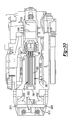
- the fastening tool 10 may further include an stop mechanism 2050 to inhibit the activation arm 806 from engaging the driver 32 to the flywheel 42 as shown in Figure 2.
- the stop mechanism 2050 may include a rack 2052, a spring 2054 and an actuating arm 2056.
- the rack 2052 may be mounted to the housing shell 1050b for translation thereon in a generally vertical direction that may be parallel to the axis 118.
- the rack 2052 may include one or more rack engagements 2060, a generally H-shaped body 2062 and an arm 2064.
- the rack engagements 2060 may be coupled to the body 2062 and may have a sloped engagement surface 2070 with teeth 2072 formed thereon.
- the body 2062 may define one or more guides 2074 and a crossbar 2076, which may be disposed between the guides 2074.
- the guides 2074 may be received into corresponding structures, such as a guide tab 2080 and a spring cavity 2082, that are formed on the housing shell 1050b.
- the structures on the housing shell 1050b and the guides 2074 cooperate so that the rack 2052 may be translated in a predetermined direction between an extended position and a retracted position. Placement of the rack 2052 in the extended position permits the teeth 2072 of the sloped engagement surface 2070 to engage an upper one of the laterally extending central members 872 (Fig. 47) of the arm structure 850 (Fig. 47), while placement of the rack 2052 in the retracted position locates the teeth 2072 of the sloped engagement surface 2070 in a position that does not inhibit movement of the arm structure 850 (Fig. 47) about the pivot arm pin 854.
- a feature such as a bayonet 2080, may be incorporated into the housing shell 1050b to engage the rack 2052 when the rack 2052 is in the extended position so as to inhibit the rack 2052 from disengaging the housing shell 1050b.
- the bayonet 2080 engages the lower end of the crossbar 2076 when the rack 2052 is in the extended position.
- the actuating arm 2056 is configured to engage the arm 2064 on the rack 2052 and selectively urge the rack 2052 into the disengaged position.
- the actuating arm 2056 is mechanically coupled to the mechanical linkage of a contact trip mechanism 2090 (Fig. 1) that is associated with the nosepiece assembly 22 (Fig. 1).
- a contact trip mechanism 2090 (Fig. 1) that is associated with the nosepiece assembly 22 (Fig. 1).
- contact trip mechanisms are typically employed to identify those situations where the nosepiece of a tool has been brought into a desired proximity with a workpiece.
- Contact trip mechanisms typically employ a mechanical linkage that interacts with (e.g., pushes, rotates) a trigger, or a valve or, in the example provided, an electrical switch, to permit the fastening tool to be operated.
- the actuating arm 2056 is coupled to the mechanical linkage and as the contact trip mechanism 2090 (Fig. 1) biases the mechanical linkage downwardly (so that the contact trip is position in an extended position), the actuating arm 2056 is likewise positioned in a downward position that permits the rack 2052 to be moved into the extended position. Placement of the contact trip mechanism 2090 (Fig. 1) against a workpiece pushes the mechanical linkage upwardly by a sufficient distance, which closes an air gap between the actuating arm 2056 and the arm 2064, to thereby cause the actuating arm 2056 to urge the rack 2052 upwardly into the disengaged position.
- the backbone 14 may carry an upper bumper 2100 and a lower bumper 2102.
- the upper bumper 2100 may be coupled to the backbone 14 in any desired manner and may include a beatpiece 2110 and a damper 2112. Formation of the upper bumper 2100 from two pieces permits the materials to be tailored to specific tasks.
- the beatpiece 2110 may be formed from a relatively tough material, such as glass-filled nylon, while the damper 2112 may be formed from a material that is relatively more resilient than that of the beatpiece 2110, such as chlorobutyl rubber.
- the combination of the beatpiece 2110 and the damper 2112 permit the upper bumper 2100 to be formed with highly effective impact absorbing characteristics and a highly impact resistant interface where the driver 32 (Fig. 49) contacts the upper bumper 2100.
- the beatpiece 2110 may be trapezoidal in shape, having a sloped lower surface 2116, and may include a cavity 2118 having a ramp 2120 that conforms to the arcuate end surface 570 of the abutment 524 that is formed on the upper end of the driver 32.
- the arcuate end surface 570 of the abutment 524 and the ramp 2120 of the beatpiece 2110 may be shaped so that contact between the arcuate end surface 570 and the ramp 2120 urges the driver 32 horizontally outward away from the flywheel assembly 250 to thereby ensure that the driver 32 does not contact the flywheel assembly 250 when the driver 32 is being returned or when the driver 32 is at rest.
- the arcuate end surface 570 and the ramp 2120 may also be shaped so that contact between the arcuate end surface 570 and the ramp 2120 causes the driver to deflect laterally, rather than vertically or toward the fasteners F, so that side-to-side movement (i.e., in the direction of arrow 2126) of the driver 32 within the cavity 2118 is initiated when the driver 32 impacts the upper bumper 2100 and the driver 32 is less apt to travel vertically downwardly toward the flywheel 42.
- the damper 2112 may be configured to be fully or partially received into the beatpiece 2110 to render the upper bumper 2100 relatively easier to install to the backbone 14.
- the beatpiece 2110 includes an upper cavity 2130 having an arcuate upper surface 2132 that is generally parallel to the ramp 2120, while the damper 2112 includes a lower surface 2134 that conforms to the arcuate upper surface 2132 when the damper 2112 is installed to the beatpiece 2110.
- the upper bumper 2100 may be inserted into an upper bumper pocket 2150 that is formed in the backbone 14.
- the upper bumper pocket 2150 may include a pair of side walls 2152, an upper wall 2154 and a pair of lower ribs 2156, each of which being formed on an associated one of the side walls 2152.
- the side walls 2152 may be generally orthogonally to the upper wall 2154 and the ribs 2156 may be angled to match the sloped lower surface 2116 of the beatpiece 2110.
- the angled ribs 2156 facilitate installation of the upper bumper 2100 to the backbone 14, since the narrow end of the upper bumper 2100 is readily received into the upper bumper pocket 2150 and the angled ribs 2156 permit the upper bumper 2100 to be slid both into the upper bumper pocket 2150 and upwardly against the upper wall 2154.
- a feature 2160 (Fig. 65) that is formed onto the backbone cover 16 (Fig. 65) may contact or otherwise restrain the upper bumper 2100 so as to maintain the upper bumper 2100 within the upper bumper pocket 2150.
- the lower bumper 2102 may be coupled to the backbone 14 in any desired manner and may be configured to contact a portion of the driver 32, such as the contact surfaces 670 of the bumper tabs 632, to prevent the driver 32 from directly contacting the backbone 14 at the end of the stroke of the driver 32.
- the lower bumper 2102 may be configured of any suitable material and may have any desired configuration, but in the example provide a pair of lower bumper members 2200 that are disposed in-line with a respective one of the bumper tabs 632 on the driver 32.
- the bumper members 2200 are interconnected by a pair of ribs 2202 and include locking tabs 2204 that extend from a side opposite the other bumper member 2200.
- the lower bumper 2102 may be configured to be slidably engaged to the backbone 14 such that the locking tabs 2204 and one of the ribs 2202 are disposed in a mating recess 2210 that is formed in the backbone 14 and the bumper members 2102 abut a flange 2212 that extends generally perpendicular to the axis 118.
- the backbone cover 16 may be configured with one or more mating tabs 2216 that cooperate with the backbone 14 to capture the other rib 2202 to thereby immobilize the lower bumper 2102.
- the lower bumper members 2200 may have a cylindrical upper surface 2230 that may be aligned about an axis 2232, which may be generally perpendicular to both the axis 118 and the axes 2234 about which the contact surfaces 670 may be formed. Configuration in this manner permits the lower bumper members 2200 to loaded in a consistent manner without the need to precisely guide the driver 32 onto the lower bumper members 2200 and without transmitting a significant shear load to the lower bumper members 2200.
- each lower bumper member 2200 may be formed with a channel 2270 that extends about the lower bumper member 2200 inwardly of the perimeter of the lower bumper member 2200 as shown in Figures 54 through 57.
- the channel 2270 may be formed in a lower surface of the lower bumper member 2200 so as to be open at the bottom of the lower bumper member 2200 (as shown), or may be a closed cavity that is disposed within the lower bumper member 2200 (not shown). While the lower bumper member 2200 and the channel 2270 are illustrated to have a generally rectangular shape, those of ordinary skill in the art should appreciate from this disclosure that the lower bumper member 2200 and the channel 2270 may be otherwise formed.
- the control unit 20 may include various sensors (e.g., a trigger switch 2300 and contact trip switch 2302) for sensing the state of various components, e.g., the trigger 2304 (Fig. 1) and the contact trip mechanism 2090 (Fig. 1), respectively, and generating signals in response thereto.
- the control unit 20 may further include a controller 2310 for receiving the various sensor signals and controlling the fastening tool 10 (Fig. 1) in response thereto.
- the control unit 20 may further include a DC/DC converter 2312 with a switching power supply 2314 for pulse-modulating the electrical power that is provided by the battery pack 26 and supplied to the motor 40.
- the switching power supply 2314 switches (i.e., turns on and off) to control its output to the motor 40 to thereby apply power of a desired voltage to the motor 40. Consequently, electrical power of a substantially constant overall voltage may be provided to the motor 40 regardless of the voltage of the battery pack 26 by adjusting the length of time at which the switching power supply 2314 has been turned off and/or on.
- the housing assembly 12 may include discrete housing shells 2400a and 2400b that may be formed from a thermoplastic material and which cooperate to define a body portion 2402 and a handle portion 2404.
- the body portion 2402 may define a housing cavity 2410 that is sized to receive the backbone 14, the drive motor assembly 18 and the control unit 20 therein.
- the handle portion 2404 may extend from the body portion 2402 and may be configured in a manner that permits an operator to manipulate the fastening tool 10 in a convenient manner.
- the handle portion 2404 may include a mount 2418 to which the battery pack 26 may be releasably received, and/or a wire harness guard 2420 that confines the wire harness 2322 to a predetermined area within the handle portion 2404.
- the mount 2418 may include a recess 2422 that is configured to be engaged by a latch 2424 on the battery pack 26 so that the battery pack 26 may be fixedly but removably coupled to the handle portion 2404.
- the wire harness guard 2420 may include a plate member 2430 that extends inwardly from the housing shell 2400a and a plurality of ribs 2432 that cooperate to form a cavity into which a tool terminal block 2436 may be received.
- the tool terminal block 2436 includes electrical terminals that engage corresponding terminals that are formed on the battery pack 26.
- portions of the housing assembly 12 may be overmolded to create areas on the exterior of and/or within the housing assembly 12 that enhance the capability of the housing assembly 12 to be gripped by an operator, provide vibration damping, and/or form one or more seals.
- Such techniques are described in more detail in commonly assigned U.S. Patent No. 6,431,289 entitled “Multispeed Power Tool Transmission” and copending U.S. Patent Application No. 09/963,905 entitled “Housing With Functional Overmold", both of which are hereby incorporated by reference as if fully set forth herein.
- the housing shells 2400a and 2400b may employ a plurality of locating features to locate the housing shells 2400a and 2400b to one another as well as to the backbone 14.
- the housing shells 2400a and 2400b are located to one another with several sets of bosses and a rib-and-groove feature.
- Each set of bosses includes a first boss 2450 and a second boss 2542 into which the first boss 2450 is received.
- the set of bosses may be configured to receive a threaded fastener 2456 therein to secure the housing shells 2400a and 2400b to one another.
- the rib-and-groove feature may include a rib member 2460, which extends from a first one of the housing shells, e.g., housing shell 2400a, about selected portions of the surface 2462 that abuts the other housing shell, and a mating groove 2468 that is formed in the other housing shell, e.g., housing shell 2400b.
- the housing assembly 12 may also include a trigger mount 2470 and a belt clip mount, which is discussed in greater detail below.
- the trigger mount 2470 may be configured in an appropriate manner to as to accept a desired trigger, including a rotary actuated trigger or a linearly actuated trigger.
- the trigger 2304 has characteristics of both a rotational actuated trigger and a linearly actuated trigger and as such, the trigger mount may include a backplate 2480, a trigger opening 2482, a pair of first trigger retainers 2484, and a pair of second trigger retainers 2486.
- the backplate 2480 may be formed on one or both of the housing shells 2400a and/or 2400b and includes an abutting surface 2490 that extends generally perpendicular to the trigger opening 2482.
- Each of the first and second trigger retainers 2484 and 2486 may be defined by one or more wall members 2492 that extends from an associated housing shell (e.g., housing shell 2400a) and defines first and second cams 2500 and 2502, respectively.
- a trigger assembly 2510 may include the trigger 2304 and a trigger spring 2512, which may be a conventional compression spring. Except as noted below, the trigger 2304 may be substantially symmetrical about its longitudinal centerline and may include a spring mount 2520, a first pair of pins 2522 and a second set of pins 2524.
- the spring mount 2520 may be configured to receive the trigger spring 2512 thereon and may serve as a guide for the trigger spring 2512 when it is compressed.
- the first and second sets of pins 2522 and 2524 extend from the opposite lateral sides of the trigger 2304 and are configured to be disposed in the first and second cams 2500 and 2502, respectively, that are formed in the housing assembly 12.
- the wall members 2492 of the second trigger retainers 2486 guide the second pins 2524 along the second axis 2508.
- the trigger 2304 has a "feel" that is similar to a linearly actuated trigger, but is relatively robust in design like a rotationally actuated trigger.
- the shape and angle of the cams 2500 and 2502 are a function of the path over which the user's finger travels.
- the cam 2502 may be generally parallel to or in-line with the center of the handle portion 2404.
- the trigger 2304 may be translated from an initial position (i.e., an unactuated position) into the handle portion 2404 to an end position (i.e., an actuated position). Movement of the trigger 2304 from the initial position to the end position is controlled at a first point by the cam 2502 (i.e., the trigger 2304 moves along the cam 2502).
- the trigger 2304 may further include a switch arm 2550 that is configured to engage an actuator 2552 of a trigger switch 2300 that is employed in part to actuate the fastening tool 10.
- the trigger switch 2300 is a microswitch and the actuator 2552 is a spring-biased plunger that is slidably mounted to the backbone 14.
- the switch arm 2550 is configured to contact and move the actuator 2552 when the trigger 2304 is depressed so as to change the state of the microswitch.
- the trigger switch 2300 is configured such that the actuator 2552 is biased into contact with the microswitch and the trigger 2304 is employed to push the actuator 2552 away from the microswitch. Accordingly, the only force that is applied to the microswitch is the force of the spring 2558 that biases the actuator 2552 into contact with the trigger switch 2300; no forces are applied to the microswitch when the trigger 2304 is depressed, regardless of how far the actuator 2552 is over-traveled.
- Bosses 2604 may be formed into the backbone cover 16 to receive threaded fasteners (not shown) therethrough to permit the backbone cover 16 to be fixedly but removably secured to the backbone 14.
- Configuration of the fastening tool 10 in this manner provides a means by which an operator may readily gain access to the drive motor assembly 18 to inspect and/or service components, such as the flywheel 42 (Fig. 2), the driver 32 (Fig. 2) and the return mechanism 36 (Fig. 2), as well as provides a structural element that is relatively strong and durable and which may extend over the upper end and/or lower end of the housing assembly 12.
- the housing assembly 12 may be configured to cover the top of the backbone 14.
- control unit 20 may activate the motor 40 upon the occurrence of a predetermined condition, such as a change in the state of the contact trip switch 2302 that indicates that the contact trip mechanism 2090 has been abutted against a workpiece, and thereafter activate the actuator 44 upon the occurrence of a second predetermined condition, such as a change in the state of the trigger switch 2300 that indicates that the trigger 2304 has been depressed by the operator.
- a predetermined condition such as a change in the state of the contact trip switch 2302 that indicates that the contact trip mechanism 2090 has been abutted against a workpiece
- a second predetermined condition such as a change in the state of the trigger switch 2300 that indicates that the trigger 2304 has been depressed by the operator.
- the spring 858 of the activation arm 806 provides a degree of compliance between the activation arm 806 and the roller assembly 808 that permits the follower 50 to pivot away from the driver 32 to thereby inhibit the activation arm assembly 804 from overloading the driver 32 and/or the flywheel assembly 250.
- the magnitude of the force with which the driver 32 may impact the follower 50 may be reduced in such situations through the pivoting of the eccentrics 922 about the axle stubs 974 such that the stop members 976 travel toward or are disposed in an end of the range limit slots 942 opposite the end into which they are normally biased.
- Rotation of the eccentrics 922 pivots the follower 50 away from the driver 32 when the driver 32 bounces off the lower bumper 2102.
- the second cam portion 562 (Fig. 23) is provided on the cam profile 522 (Fig. 23) of the driver 32.
- the second cam portion 562 (Fig.
- the drive motor assembly 18' can include a power source 30', a driver 32', a follower assembly 34', and a return mechanism 36'.
- the power source 30', the driver 32' and the return mechanism 36' can be constructed and operated in a manner that can be similar to that which is described above and as such, a detailed description of these components need not be provided herein.
- the follower assembly 34' can include an actuator 44' and an activation arm assembly 804' that can include a first arm 3000, a second arm 3002, a third arm 3004, a first roller 3006, a second roller 3008 and a biasing mechanism 3010.
- the biasing mechanism 3010 can include a first cap 3200, a second cap 3202, a fastener 3204 and a spring 3206.
- the first cap 3200 can have a generally cylindrical body member 3210 and a flange 3212 that can be disposed about the body member 3210.
- the body member 3210 can include an internally threaded aperture 3214 and can be received in the hole 3090 in the first portion 3080 of the third arm 3004.
- the flange 3212 can abut a side of the first portion 3080 of the third arm 3004.
Landscapes
- Engineering & Computer Science (AREA)
- Mechanical Engineering (AREA)
- Portable Nailing Machines And Staplers (AREA)
Applications Claiming Priority (1)
| Application Number | Priority Date | Filing Date | Title |
|---|---|---|---|
| US11/586,104 US8302833B2 (en) | 2004-04-02 | 2006-10-25 | Power take off for cordless nailer |
Publications (3)
| Publication Number | Publication Date |
|---|---|
| EP1916068A2 true EP1916068A2 (fr) | 2008-04-30 |
| EP1916068A3 EP1916068A3 (fr) | 2010-02-24 |
| EP1916068B1 EP1916068B1 (fr) | 2015-07-01 |
Family
ID=39047930
Family Applications (1)
| Application Number | Title | Priority Date | Filing Date |
|---|---|---|---|
| EP07117710.9A Active EP1916068B1 (fr) | 2006-10-25 | 2007-10-02 | Prise de force pour cloueur sans fil |
Country Status (3)
| Country | Link |
|---|---|
| US (5) | US8302833B2 (fr) |
| EP (1) | EP1916068B1 (fr) |
| CN (1) | CN201261183Y (fr) |
Cited By (3)
| Publication number | Priority date | Publication date | Assignee | Title |
|---|---|---|---|---|
| EP2116335A1 (fr) * | 2008-05-09 | 2009-11-11 | Makita Corporation | Outils portables |
| EP2716409A3 (fr) * | 2012-10-04 | 2017-12-20 | Black & Decker Inc. | Système d'activation doté d'un bras multi-angles et mécanisme de libération de blocage |
| KR20250150816A (ko) * | 2024-04-12 | 2025-10-21 | 제일타카 주식회사 | 전동식 네일러 |
Families Citing this family (58)
| Publication number | Priority date | Publication date | Assignee | Title |
|---|---|---|---|---|
| US8302833B2 (en) | 2004-04-02 | 2012-11-06 | Black & Decker Inc. | Power take off for cordless nailer |
| US7503401B2 (en) * | 2004-04-02 | 2009-03-17 | Black & Decker Inc. | Solenoid positioning methodology |
| US10882172B2 (en) | 2004-04-02 | 2021-01-05 | Black & Decker, Inc. | Powered hand-held fastening tool |
| JP4939985B2 (ja) * | 2007-03-16 | 2012-05-30 | 株式会社マキタ | 打込み作業工具 |
| US7556184B2 (en) * | 2007-06-11 | 2009-07-07 | Black & Decker Inc. | Profile lifter for a nailer |
| US9216502B2 (en) | 2008-04-03 | 2015-12-22 | Black & Decker Inc. | Multi-stranded return spring for fastening tool |
| US8534527B2 (en) * | 2008-04-03 | 2013-09-17 | Black & Decker Inc. | Cordless framing nailer |
| DE102008023927A1 (de) * | 2008-05-16 | 2009-11-19 | Andreas Stihl Ag & Co. Kg | Arbeitsgerät |
| TWI385058B (zh) * | 2010-04-26 | 2013-02-11 | Basso Ind Corp | Electric nail gun drive device |
| TWI381915B (zh) * | 2010-09-16 | 2013-01-11 | Basso Ind Corp | An electric nail gun with an error prevention function |
| TWI392565B (zh) * | 2010-09-28 | 2013-04-11 | Basso Ind Corp | The drive unit of the electric nail gun |
| KR101643680B1 (ko) * | 2012-02-10 | 2016-07-28 | 다이슨 테크놀러지 리미티드 | 진공 청소기 및 이 것을 위한 배터리 팩 |
| US9827658B2 (en) | 2012-05-31 | 2017-11-28 | Black & Decker Inc. | Power tool having latched pusher assembly |
| US11229995B2 (en) | 2012-05-31 | 2022-01-25 | Black Decker Inc. | Fastening tool nail stop |
| US9399281B2 (en) | 2012-09-20 | 2016-07-26 | Black & Decker Inc. | Stall release lever for fastening tool |
| US9577493B2 (en) * | 2012-09-20 | 2017-02-21 | Black & Decker Inc. | Motor and electronics cooling system for a high power cordless nailer |
| US9346158B2 (en) | 2012-09-20 | 2016-05-24 | Black & Decker Inc. | Magnetic profile lifter |
| US9189908B2 (en) * | 2013-02-01 | 2015-11-17 | Sampson Kwasi D | Hand-held projectile dispenser |
| FR3006933B1 (fr) * | 2013-06-13 | 2015-12-04 | Illinois Tool Works | Outil de fixation a tir indirect, organe de propulsion et element de fixation portant cet organe pour l'outil, et procede de pose d'un element de fixation |
| TWI458603B (zh) * | 2013-08-01 | 2014-11-01 | Basso Ind Corp | Power tools for heat dissipation devices |
| US12502756B2 (en) | 2013-10-09 | 2025-12-23 | Black & Decker Inc. | High inertia driver system |
| US10434634B2 (en) | 2013-10-09 | 2019-10-08 | Black & Decker, Inc. | Nailer driver blade stop |
| EP2881222A1 (fr) * | 2013-12-04 | 2015-06-10 | HILTI Aktiengesellschaft | Dispositif d'entraînement |
| TWI607839B (zh) * | 2014-06-05 | 2017-12-11 | Basso Ind Corp | Portable power tool and impact block resetting device |
| AU2015354771B2 (en) | 2014-11-26 | 2018-07-26 | Techtronic Industries Co. Ltd. | Battery pack |
| US10193417B2 (en) | 2014-12-18 | 2019-01-29 | Black & Decker Inc. | Brushless motor assembly for a fastening tool |
| US10322501B2 (en) | 2015-01-16 | 2019-06-18 | Black & Decker Inc. | Fastening tool having timed ready to fire mode |
| US10286533B2 (en) | 2015-05-08 | 2019-05-14 | Black & Decker Inc. | Depth adjustment mechanism for a fastening tool |
| TWI532571B (zh) * | 2015-10-12 | 2016-05-11 | Electric nail gun drive device | |
| US12544893B2 (en) | 2016-06-20 | 2026-02-10 | Black & Decker Inc. | Feed piston pressure tube |
| US11325235B2 (en) | 2016-06-28 | 2022-05-10 | Black & Decker, Inc. | Push-on support member for fastening tools |
| US11267114B2 (en) | 2016-06-29 | 2022-03-08 | Black & Decker, Inc. | Single-motion magazine retention for fastening tools |
| US11279013B2 (en) * | 2016-06-30 | 2022-03-22 | Black & Decker, Inc. | Driver rebound plate for a fastening tool |
| US11400572B2 (en) | 2016-06-30 | 2022-08-02 | Black & Decker, Inc. | Dry-fire bypass for a fastening tool |
| US10987790B2 (en) * | 2016-06-30 | 2021-04-27 | Black & Decker Inc. | Cordless concrete nailer with improved power take-off mechanism |
| EP3269512B1 (fr) * | 2016-07-12 | 2018-12-05 | Makita Corporation | Outil de fixation |
| WO2018051484A1 (fr) | 2016-09-16 | 2018-03-22 | 日産自動車株式会社 | Procédé de traitement thermique et procédé d'assemblage pour composant ajusté |
| EP3323560A1 (fr) | 2016-11-18 | 2018-05-23 | HILTI Aktiengesellschaft | Appareil de pose entraîné par volant d'inertie |
| US10926385B2 (en) | 2017-02-24 | 2021-02-23 | Black & Decker, Inc. | Contact trip having magnetic filter |
| JP2019081228A (ja) | 2017-10-31 | 2019-05-30 | 株式会社マキタ | 打込み工具 |
| US10723005B2 (en) * | 2018-03-28 | 2020-07-28 | Black & Decker Inc. | Electric fastener driving tool assembly including a driver home position sensor |
| WO2019241225A1 (fr) | 2018-06-11 | 2019-12-19 | Milwaukee Electric Tool Corporation | Dispositif d'entraînement d'élément de fixation alimenté par ressort à gaz |
| US12427634B2 (en) | 2018-06-11 | 2025-09-30 | Milwaukee Electric Tool Corporation | Gas spring-powered fastener driver |
| EP3654497B1 (fr) | 2018-11-15 | 2026-04-08 | Black & Decker Inc. | Insert de rétention d'enroulement pour moteur sans balai |
| US10967492B2 (en) | 2018-11-19 | 2021-04-06 | Brahma Industries LLC | Staple gun with automatic depth adjustment |
| US11141849B2 (en) | 2018-11-19 | 2021-10-12 | Brahma Industries LLC | Protective shield for use with a staple gun |
| US10933521B2 (en) | 2018-11-19 | 2021-03-02 | Brahma Industries LLC | Staple gun with self-centering mechanism |
| JP7200684B2 (ja) * | 2019-01-15 | 2023-01-10 | マックス株式会社 | 打ち込み工具 |
| US11806854B2 (en) | 2019-02-19 | 2023-11-07 | Brahma Industries LLC | Insert for palm stapler, a palm stapler and a method of use thereof |
| JP7388830B2 (ja) * | 2019-06-17 | 2023-11-29 | 株式会社マキタ | 打込み工具 |
| US10946504B1 (en) | 2019-09-16 | 2021-03-16 | Tricord Solutions, Inc. | Fastener driving apparatus |
| EP4081371A2 (fr) * | 2019-12-24 | 2022-11-02 | Black & Decker Inc. | Outil de fixation entraîné par volant |
| EP4063049A1 (fr) * | 2021-03-24 | 2022-09-28 | Airbus Operations, S.L.U. | Dispositif et procédé de forage avec adaptation automatique des paramètres de forage |
| EP4461473A1 (fr) | 2023-04-05 | 2024-11-13 | Black & Decker, Inc. | Guide-fil et unité de retenue pour outil électrique |
| US20250088072A1 (en) | 2023-09-12 | 2025-03-13 | Black & Decker Inc. | Motor bearing shield |
| WO2025059312A1 (fr) | 2023-09-12 | 2025-03-20 | Black & Decker, Inc. | Mécanisme de libération de blocage et atténuation d'ingestion de débris pour un outil de fixation |
| WO2025160078A1 (fr) | 2024-01-22 | 2025-07-31 | Black & Decker Inc. | Moteur à rotor externe pour un outil électrique |
| GB2700834A (en) * | 2024-05-20 | 2026-03-18 | Bosch Gmbh Robert | Fastener driver tool |
Family Cites Families (201)
| Publication number | Priority date | Publication date | Assignee | Title |
|---|---|---|---|---|
| US997638A (en) * | 1910-08-13 | 1911-07-11 | Eugene Rynearson | Pavement-breaking machine. |
| US1517101A (en) | 1920-08-30 | 1924-11-25 | Splitdorf Electrical Co | Support for electric machines |
| US1715866A (en) * | 1923-08-17 | 1929-06-04 | Firm Neufeldt & Kuhnke Betr Sg | Asynchronous machine with condensers |
| US1482464A (en) * | 1923-10-09 | 1924-02-05 | Harrison D Flegel | Sewing-machine-motor bracket |
| US1611814A (en) | 1924-05-29 | 1926-12-21 | Thomas J Butler | Gun |
| US1647493A (en) | 1924-10-10 | 1927-11-01 | Kenneth S Startup | Power hammer |
| US1600266A (en) | 1925-04-01 | 1926-09-21 | Armstrong Frederick | Clamp for holding knives |
| US1629189A (en) * | 1925-05-04 | 1927-05-17 | Frank L Weaver | Electrical connecter |
| US1964558A (en) | 1932-05-16 | 1934-06-26 | Campbell Given | Air conditioning apparatus |
| US2320450A (en) * | 1942-07-16 | 1943-06-01 | Ismael Spencer | Belt clip for pistols |
| US2379784A (en) * | 1943-02-06 | 1945-07-03 | Ibm | Gun |
| US2697179A (en) | 1952-03-11 | 1954-12-14 | Singer Mfg Co | Ventilation of dynamoelectric machines |
| US2714209A (en) * | 1952-07-10 | 1955-08-02 | Bostitch Inc | Closure means for staple driveway |
| US2737941A (en) * | 1952-12-13 | 1956-03-13 | Marlo J Carrau | Mechanical gun |
| US2786672A (en) * | 1954-07-15 | 1957-03-26 | Mid States Gummed Paper Co | Tape-feeding mechanism |
| US2869824A (en) * | 1957-03-26 | 1959-01-20 | Raymond Int Inc | Automatic drop weight for boring |
| GB844715A (en) | 1958-05-02 | 1960-08-17 | Grymak Ltd | Improvements in or relating to stapling appliances |
| US3074347A (en) * | 1958-11-21 | 1963-01-22 | Tokheim Corp | Electric drive unit and mounting |
| US3018584A (en) * | 1959-06-05 | 1962-01-30 | Angelo G Passariello | Pinch-spin tops |
| US3194324A (en) * | 1963-03-13 | 1965-07-13 | Signode Corp | Fastener driving tool |
| US3172124A (en) * | 1963-04-01 | 1965-03-09 | Spotnails | Pneumatically operated fastener driving machines |
| US3215324A (en) | 1963-11-29 | 1965-11-02 | Fastener Corp | Fastener driving apparatus |
| DE1302136B (fr) | 1964-03-11 | 1970-01-22 | ||
| US3194321A (en) | 1964-03-23 | 1965-07-13 | Sande Floyd Arthur | Combination hitch, depth control and spring release for rod weeders |
| US3293462A (en) | 1964-07-31 | 1966-12-20 | Spalding A G & Bros Inc | Power unit for toys or the like |
| US3408887A (en) | 1966-11-18 | 1968-11-05 | Standard Pressed Steel Co | Adjustable shoulder bolt for use in a stripper means |
| CH466413A (fr) * | 1967-11-28 | 1968-12-15 | Mefina Sa | Dispositif de support d'un moteur électrique |
| US3500940A (en) * | 1968-08-15 | 1970-03-17 | Sprague & Henwood Inc | Free fall hammer apparatus |
| US3535906A (en) | 1968-09-03 | 1970-10-27 | Dwain K Swick | Cylinder head straightening method |
| DE1943000C3 (de) * | 1969-08-23 | 1973-11-08 | Bukama Gmbh Hannover, 3005 Hemmingenwesterfeld | Zufuhreinrichtung fur Befesti gungsmittel, die mit einem Handnagier eingetrieben werden, insbesondere fur Nagel |
| US3618350A (en) * | 1969-12-15 | 1971-11-09 | Boeing Co | Reusable tooling for electromagnetic forming |
| US3694680A (en) | 1970-10-06 | 1972-09-26 | Murphy Ind Inc G W | Stamped shell sheet metal frame module for a power tool |
| US3688138A (en) * | 1970-10-06 | 1972-08-29 | Murphy Ind Inc G W | Subframe for a power tool employing two plate-like elements with cut out portions for motor and transmission |
| US3700987A (en) | 1971-03-29 | 1972-10-24 | E Systems Inc | Pulse modulation motor control |
| US3817091A (en) * | 1971-05-11 | 1974-06-18 | L Frederick | Pile driver drive cap |
| US3703654A (en) * | 1971-06-30 | 1972-11-21 | Ralph Karubian | Hand tool with magnetic brake |
| US3774293A (en) | 1971-09-13 | 1973-11-27 | Signode Corp | Fastener driving tool |
| US3716200A (en) * | 1971-10-21 | 1973-02-13 | Roannais Constr Textiles | Apparatus for reciprocating a traveller |
| US3858780A (en) * | 1973-01-08 | 1975-01-07 | Spotnails | Fastener-driving tool |
| US3853257A (en) | 1973-06-18 | 1974-12-10 | Spotnails | Self-clearing nose section for a powered fastener-driving tool |
| US4042036A (en) * | 1973-10-04 | 1977-08-16 | Smith James E | Electric impact tool |
| CA1030701A (fr) | 1973-10-04 | 1978-05-09 | James E. Smith | Outil electrique a percussion |
| US3957192A (en) * | 1973-11-02 | 1976-05-18 | Joh. Friedrich Behrens Metallwaren-Fabrik | Fastener-driving tool |
| US3848309A (en) | 1973-11-12 | 1974-11-19 | Chrysler Corp | Pulley method of manufacture |
| US3937286A (en) * | 1974-05-13 | 1976-02-10 | Wagner Carl F | Fence post driver |
| US3946486A (en) * | 1974-06-12 | 1976-03-30 | Sperry Rand Corporation | Portable electrical shaver with pivotally mounted motor |
| US4763347A (en) * | 1983-02-02 | 1988-08-09 | General Electric Company | Control system, electronically commutated motor system, blower apparatus and methods |
| DE2504094C2 (de) | 1975-01-31 | 1985-03-21 | Signode Corp., Glenview, Ill. | Abfangvorrichtung für den Schlagkolben eines pneumatisch betätigbaren Eintreibwerkzeugs |
| US3934778A (en) * | 1975-02-13 | 1976-01-27 | Textron, Inc. | Staple driving device with improved staple jam clearing mechanism |
| DE2510858C2 (de) | 1975-03-12 | 1987-01-08 | Signode Corp., Glenview, Ill. | Einrichtung zum Abfangen des Schlagkolbens eines pneumatisch betätigbaren Eintreibwerkzeugs |
| US3983429A (en) | 1975-05-08 | 1976-09-28 | Westinghouse Electric Corporation | Adjustable motor base |
| US4204622A (en) * | 1975-05-23 | 1980-05-27 | Cunningham James D | Electric impact tool |
| US4083481A (en) * | 1977-03-10 | 1978-04-11 | Motorola, Inc. | Detachable mounting clip arrangement for miniature portable apparatus or the like |
| JPS53127025A (en) | 1977-04-09 | 1978-11-06 | Auto Stamp Kenkyusho Kk | Automatic certifying composite machine |
| US4323127A (en) * | 1977-05-20 | 1982-04-06 | Cunningham James D | Electrically operated impact tool |
| US4121745A (en) | 1977-06-28 | 1978-10-24 | Senco Products, Inc. | Electro-mechanical impact device |
| US4129240A (en) | 1977-07-05 | 1978-12-12 | Duo-Fast Corporation | Electric nailer |
| CH626434A5 (en) | 1977-08-02 | 1981-11-13 | Haas Eduard Volkmann | Method and device for storing kinetic energy in a centrifugal mass |
| US4179791A (en) | 1977-12-02 | 1979-12-25 | Ncr Corporation | Variable fit fastener |
| US4131533A (en) | 1977-12-30 | 1978-12-26 | International Business Machines Corporation | RF sputtering apparatus having floating anode shield |
| US4206697A (en) * | 1978-02-22 | 1980-06-10 | California Processing Machinery | Method and apparatus for selective pitting of fruits of the drupe type |
| US4189080A (en) | 1978-02-23 | 1980-02-19 | Senco Products, Inc. | Impact device |
| US4215808A (en) * | 1978-12-22 | 1980-08-05 | Sollberger Roger W | Portable electric fastener driving apparatus |
| US4449681A (en) * | 1979-01-03 | 1984-05-22 | The Boeing Company | Aerodynamically contoured, low drag wing, engine and engine nacelle combination |
| US4298072A (en) | 1979-08-31 | 1981-11-03 | Senco Products, Inc. | Control arrangement for electro-mechanical tool |
| US4290493A (en) | 1979-09-06 | 1981-09-22 | Senco Products, Inc. | Configured impact member for driven flywheel impact device |
| US4292574A (en) | 1980-04-18 | 1981-09-29 | Anatole J. Sipin Company | Personal air sampler with electric motor driven by intermittent full-power pulses under control, between pulses, of motor's back electromotive force |
| US4566619A (en) * | 1980-07-24 | 1986-01-28 | The Kiesel Co. | Pneumatic fastener-driving tool and method |
| US4335514A (en) * | 1980-08-08 | 1982-06-22 | Black & Decker Inc. | Switch-brake interlock for chain saw |
| DE3043264A1 (de) * | 1980-11-15 | 1982-07-08 | Robert Bosch Gmbh, 7000 Stuttgart | Elektronische zweihandsicherung fuer werkzeuge |
| DE3047662C2 (de) * | 1980-12-18 | 1985-02-21 | Karl M. Reich Maschinenfabrik GmbH, 7440 Nürtingen | Puffersystem bei Einschlaggeräten |
| US4403722A (en) | 1981-01-22 | 1983-09-13 | Signode Corporation | Combustion gas powered fastener driving tool |
| US4483474A (en) | 1981-01-22 | 1984-11-20 | Signode Corporation | Combustion gas-powered fastener driving tool |
| DE3119956C2 (de) * | 1981-05-20 | 1984-11-22 | Joh. Friedrich Behrens AG, 2070 Ahrensburg | Schallgedämpftes Eintreibgerät für Befestigungsmittel |
| DE3125860C2 (de) * | 1981-07-01 | 1983-12-15 | J. Wagner Gmbh, 7990 Friedrichshafen | Elektrisch betriebenes Handarbeitsgerät |
| US4457462A (en) * | 1981-08-26 | 1984-07-03 | Taormina Umberto C | Tool holder |
| US4480513A (en) | 1981-11-16 | 1984-11-06 | Mcgard, Inc. | Bolt-lock structure |
| JPS58502044A (ja) * | 1981-12-10 | 1983-12-01 | カニンガム,ジエ−ムス デイ− | 電動駆動の衝撃工具とその操作方法 |
| US4436236A (en) * | 1982-03-22 | 1984-03-13 | Senco Products, Inc. | Front gate and latch assembly for the guide body of an industrial fastener driving tool |
| WO1987002611A1 (fr) | 1985-10-29 | 1987-05-07 | Cunningham James D | Outil a percussion |
| US4558747A (en) | 1982-08-11 | 1985-12-17 | Cunningham James D | Impact devices |
| US4467952A (en) * | 1983-01-03 | 1984-08-28 | Senco Products, Inc. | Latch assembly for the front gate of the guide body of an industrial fastener driving tool |
| JPH075099B2 (ja) | 1983-02-21 | 1995-01-25 | 株式会社小松製作所 | 装軌式車両の操向制御弁装置 |
| US5069379A (en) * | 1983-03-17 | 1991-12-03 | Duo-Fast Corporation | Fastener driving tool |
| US4928868A (en) * | 1983-03-17 | 1990-05-29 | Duo-Fast Corporation | Fastener driving tool |
| US4519535A (en) * | 1983-03-29 | 1985-05-28 | Sencorp | Flywheel for an electro-mechanical fastener driving tool |
| US4544090A (en) | 1983-03-29 | 1985-10-01 | Sencorp | Elastomeric driver return assembly for an electro-mechanical fastener driving tool |
| US4747455A (en) * | 1983-05-02 | 1988-05-31 | Jbd Corporation | High impact device and method |
| JPS59182747U (ja) | 1983-05-19 | 1984-12-05 | アルプス電気株式会社 | インタ−フエ−ス回路 |
| US4828153A (en) * | 1983-12-07 | 1989-05-09 | Motorola, Inc. | Detachable belt clip assembly |
| US4635836A (en) * | 1983-12-07 | 1987-01-13 | Motorola, Inc. | Twist-off detachable belt clip assembly |
| US4572053A (en) * | 1984-02-27 | 1986-02-25 | Teleflex Incorporated | Ordnance ejector system |
| US4585747A (en) * | 1984-06-27 | 1986-04-29 | Mobil Oil Corporation | Synthesis of crystalline silicate ZSM-48 |
| US4625903A (en) | 1984-07-03 | 1986-12-02 | Sencorp | Multiple impact fastener driving tool |
| DE3506421A1 (de) | 1985-02-23 | 1986-09-04 | Heinrich Bühnen KG, 2800 Bremen | Nageleintreibgeraet mit im querschnitt zentralsymmetrischem treiber |
| US4622500A (en) | 1985-07-11 | 1986-11-11 | The Machlett Laboratories, Inc. | Electric motor controller |
| US4721170A (en) * | 1985-09-10 | 1988-01-26 | Duo-Fast Corporation | Fastener driving tool |
| US4946087A (en) * | 1985-11-01 | 1990-08-07 | Arrow Fastener Company, Inc. | Staple driving tool |
| US4700876A (en) | 1985-11-01 | 1987-10-20 | Arrow Fastener Company, Inc. | Staple driving tool |
| US4858813A (en) * | 1985-11-01 | 1989-08-22 | Arrow Fastener Company, Inc. | Staple driving tool |
| DE8704666U1 (de) * | 1986-08-02 | 1987-05-21 | Demba Metallwarenfabrik GmbH, 2072 Bargteheide | Elektrisch betriebenes Eintreibgerät |
| EP0306793B1 (fr) | 1987-09-10 | 1992-11-11 | Siemens Aktiengesellschaft | Suspension de moteur au moyen d'une attache enserrant le carter du moteur |
| US4836755A (en) * | 1988-03-22 | 1989-06-06 | Durr Dental Gmbh & Co Kg | Compressor with balanced flywheel |
| US4991763A (en) * | 1988-05-23 | 1991-02-12 | Technalytics Inc. | Surgical stapler |
| US5114065A (en) * | 1988-05-23 | 1992-05-19 | Technalytics, Inc. | Surgical stapler |
| DE3831864C2 (de) * | 1988-09-20 | 1994-01-27 | Paslode Gmbh | Ringförmiger Prellpuffer für Befestigungsmittel-Eintreibgeräte |
| US4854492A (en) * | 1988-10-14 | 1989-08-08 | Sencorp | Flywheel for an electromechanical fastener driving tool |
| US4932480A (en) * | 1988-12-16 | 1990-06-12 | Illinois Tool Works Inc. | Driving tool with air-cooled bumper |
| US4964558A (en) | 1989-05-26 | 1990-10-23 | Sencorp | Electro-mechanical fastener driving tool |
| DE4019894A1 (de) | 1989-07-15 | 1991-04-11 | Ceka Elektrowerkzeuge Ag & Co | Elektrohandwerkzeug |
| DE3924621A1 (de) | 1989-07-26 | 1991-01-31 | Hilti Ag | Setzgeraet mit eintreibkolben |
| US4988069A (en) * | 1989-11-27 | 1991-01-29 | Baxter International Inc. | Stepping motor mounting |
| US5098004A (en) * | 1989-12-19 | 1992-03-24 | Duo-Fast Corporation | Fastener driving tool |
| DE3942083A1 (de) | 1989-12-20 | 1991-06-27 | Licentia Gmbh | Handgefuehrte elektrowerkzeugmaschine |
| US4982705A (en) * | 1990-02-21 | 1991-01-08 | Tecumseh Products Company | Cam pulley and cylinder head arrangement for an overhead cam engine |
| US5165311A (en) * | 1990-06-21 | 1992-11-24 | Vsi Corporation | Pneumatic nut installation tool |
| US5033990A (en) * | 1990-07-23 | 1991-07-23 | Arthur Silverman | Pulley having spring loaded release mechanism |
| US5184941A (en) * | 1991-04-10 | 1993-02-09 | A. O. Smith Corporation | Mounting support for motor-pump unit |
| US5270631A (en) * | 1991-04-16 | 1993-12-14 | Olympus Optical Co., Ltd. | Linear DC motor driving device |
| US5201445A (en) | 1991-05-20 | 1993-04-13 | Axelman Bart I | Tool holder with self-stabilizing swivel mount |
| JP2541323Y2 (ja) * | 1991-06-21 | 1997-07-16 | 株式会社マキタ | 釘打機における釘詰まり除去装置 |
| US5148067A (en) * | 1991-07-01 | 1992-09-15 | Lasota Laurence | Latching linear motor |
| JP2553492Y2 (ja) | 1991-10-07 | 1997-11-05 | 株式会社マキタ | 電動工具におけるフック装置 |
| US5197647A (en) * | 1991-10-21 | 1993-03-30 | Illinois Tool Works Inc. | Fastener-driving tool with improved feeding mechanism |
| US5133329A (en) * | 1991-11-25 | 1992-07-28 | Illinois Tool Works Inc. | Ignition system for combustion-powered tool |
| GB9126338D0 (en) * | 1991-12-11 | 1992-02-12 | Glynwed Eng | Fastener applicator |
| US5291578A (en) * | 1992-06-15 | 1994-03-01 | First Switch, Inc. | Apparatus for controlling a vehicle fuel pump |
| US5201455A (en) * | 1992-08-21 | 1993-04-13 | Westinghouse Electric Corp. | Method for metallurgical enhancement of a failed bolt hole |
| US5406441A (en) * | 1993-01-28 | 1995-04-11 | Warda; Gary G. | Circuit and method for controlling fastener application |
| US5511715A (en) | 1993-02-03 | 1996-04-30 | Sencorp | Flywheel-driven fastener driving tool and drive unit |
| CO4130343A1 (es) * | 1993-02-03 | 1995-02-13 | Sencorp | Herramienta electromecanica para guiar grapas |
| US5366132A (en) | 1993-04-14 | 1994-11-22 | Stanley-Bostitch, Inc. | Portable fastener driving device with inadvertent impact activation prevention |
| EP0916770B1 (fr) | 1993-07-10 | 2007-01-17 | BACA Limited | Corde élastique |
| US5537025A (en) * | 1993-08-18 | 1996-07-16 | Generac Corporation | Battery charger/pre-exciter for engine-driven generator |
| US5415136A (en) * | 1993-08-30 | 1995-05-16 | Illinois Tool Works Inc. | Combined ignition and fuel system for combustion-powered tool |
| DE4340570C2 (de) * | 1993-11-29 | 2003-04-10 | Hilti Ag | Eintreibvorrichtung zum Setzen von Befestigungselementen in Aufnahmematerialien |
| JP2568736Y2 (ja) * | 1993-12-06 | 1998-04-15 | マックス株式会社 | 可搬形電動ステープル打機 |
| US5549459A (en) * | 1993-12-30 | 1996-08-27 | Westinghouse Electric Corporation | Radial bearing assembly for a high intertia flywheel of a canned motor pump |
| US5495161A (en) * | 1994-01-05 | 1996-02-27 | Sencorp | Speed control for a universal AC/DC motor |
| US5445227A (en) * | 1994-03-31 | 1995-08-29 | Heppner; Alden | Release mechanism for a hydraulic post driver |
| DE4414006C1 (de) | 1994-04-22 | 1995-07-06 | Mueller Erwin Gmbh & Co | Heft- und Nagelgerät |
| WO1996012591A1 (fr) * | 1994-10-21 | 1996-05-02 | Senco Products, Inc. | Outil pneumatique de pose de fixations et sa commande electronique |
| US5558264A (en) | 1995-02-13 | 1996-09-24 | Illinois Tool Works Inc. | Combustion-powered, fastener-driving tool with gas-actuated, fastener-feeding mechanism |
| JP3287172B2 (ja) * | 1995-04-05 | 2002-05-27 | マックス株式会社 | 釘打ち機のトリガ装置 |
| DE19521425B4 (de) | 1995-06-14 | 2007-03-29 | Robert Bosch Gmbh | Handwerkzeugmaschine mit Elektromotor, sowie deren Elektromotor mit Zentrierringen an den Stirnseiten des Polrohres |
| DE19536557C2 (de) * | 1995-10-02 | 1998-11-26 | Wolf Gmbh Richard | Werkzeugbefestigungseinrichtung für Technoskope |
| JPH09155803A (ja) * | 1995-12-08 | 1997-06-17 | Kioritz Corp | 動力作業機 |
| EP0808018B2 (fr) | 1996-05-13 | 2011-06-08 | Black & Decker Inc. | Outil électrique équipé d'un circuit de commande de moteur permettant une commande améliorée du couple délivré par l'outil électrique |
| US5810232A (en) | 1996-07-10 | 1998-09-22 | Meurer; John | Tool support |
| US5810225A (en) | 1996-11-26 | 1998-09-22 | Andrew; Richard J. | Tool support apparatus |
| US5865473A (en) * | 1997-01-21 | 1999-02-02 | Emhart Inc. | Isolated conduit system |
| DE19805577A1 (de) | 1997-02-27 | 1998-09-03 | Bosch Gmbh Robert | Elektrische Handwerkzeugmaschine |
| DE19721449C2 (de) | 1997-05-22 | 2002-04-25 | Zf Sachs Ag | Tragestruktur zum Tragen eines Elektromotors und Stellantrieb, umfassend eine derartige Tragestruktur |
| US5839638A (en) | 1997-06-26 | 1998-11-24 | Illinois Tool Works Inc | Pneumatic trim nailer |
| US5923145A (en) * | 1997-08-15 | 1999-07-13 | S-B Power Tool Company | Controller for variable speed motor |
| US5927585A (en) * | 1997-12-17 | 1999-07-27 | Senco Products, Inc. | Electric multiple impact fastener driving tool |
| EP0928667A3 (fr) | 1997-12-31 | 2001-05-23 | Porter-Cable Corporation | Outil entraíné par gaz de combustion pour enforcer des attaches avec clapet avec soupape à tiroir |
| US6158643A (en) | 1997-12-31 | 2000-12-12 | Porter-Cable Corporation | Internal combustion fastener driving tool piston and piston ring |
| US6012622A (en) * | 1998-04-20 | 2000-01-11 | Illinois Tool Works Inc. | Fastener driving tool for trim applications |
| DE29812622U1 (de) | 1998-07-15 | 1998-10-01 | Hong Bing Pneumatic Industry Co., Ltd., Shen Kang Hsiang, Taichung | Pneumatisches Werkzeug |
| US5969508A (en) | 1998-07-27 | 1999-10-19 | Motorola, Inc. | Battery charging method using battery circuitry impedence measurement to determine optimum charging voltage |
| US6422447B1 (en) * | 1998-09-18 | 2002-07-23 | Stanley Fastening Systems, L.P. | Feed system for nailer |
| US6431430B1 (en) | 1998-09-18 | 2002-08-13 | Stanley Fastening Systems, L.P. | Battery operated roofing nailer and nails therefor |
| US6499643B1 (en) | 1998-09-18 | 2002-12-31 | Stanley Fastenening Systems, L.P. | Drive channel for nailer |
| JP3676609B2 (ja) | 1998-09-29 | 2005-07-27 | 株式会社マキタ | 電動工具における吊り下げ具の装着構造 |
| JP2000117659A (ja) | 1998-10-16 | 2000-04-25 | Makita Corp | 釘打ち機のピストンダンパー構造 |
| US6296065B1 (en) | 1998-12-30 | 2001-10-02 | Black & Decker Inc. | Dual-mode non-isolated corded system for transportable cordless power tools |
| DE19908300C1 (de) | 1999-02-26 | 2000-11-09 | Fein C & E | Bügelhalter für ein Handwerkzeug |
| US6168287B1 (en) * | 1999-03-09 | 2001-01-02 | Kuo-Chen Liu | Combination of an electric-powered tool and an illuminating device received in the tool |
| JP2002540967A (ja) * | 1999-04-05 | 2002-12-03 | スタンレー ファスニング システムズ エル.ピー. | 締結具打込み工具の安全トリップ組立体およびトリップ錠止機構 |
| US6536536B1 (en) * | 1999-04-29 | 2003-03-25 | Stephen F. Gass | Power tools |
| JP2001025982A (ja) | 1999-07-13 | 2001-01-30 | Makita Corp | 操作性が向上した照明装置付き電動工具とその使用方法 |
| US6206538B1 (en) * | 1999-08-30 | 2001-03-27 | David B. Lemoine | Miser light for cordless battery operated hand tools |
| US6672498B2 (en) * | 1999-09-17 | 2004-01-06 | Stanley Fastening Sytems Lp | Feed system for nailer |
| US6909215B2 (en) * | 2000-01-28 | 2005-06-21 | John Graham Bryant | Electric motor |
| US6170729B1 (en) * | 2000-06-28 | 2001-01-09 | Basso Industry Corp. | Nailing depth adjusting device for a power nailer |
| AU2001284822A1 (en) | 2000-08-11 | 2002-02-25 | Stanley Fastening Systems, L.P. | Feed system for nailer |
| US6523860B1 (en) | 2000-10-12 | 2003-02-25 | Illinois Tool Works Inc. | Fuel cell adapter system for combustion tools |
| US6796478B2 (en) | 2000-10-12 | 2004-09-28 | Illinois Tool Works Inc. | Fuel cell adapter system for combustion tools |
| DE10055003B4 (de) | 2000-11-07 | 2004-07-15 | Novus Gmbh & Co. Kg | Eintreibgerät |
| US20020185514A1 (en) | 2000-12-22 | 2002-12-12 | Shane Adams | Control module for flywheel operated hand tool |
| US6669072B2 (en) | 2000-12-22 | 2003-12-30 | Senco Products, Inc. | Flywheel operated nailer |
| US6755336B2 (en) | 2000-12-22 | 2004-06-29 | Kevin A. Harper | Return mechanism for a cyclic tool |
| US6607111B2 (en) | 2000-12-22 | 2003-08-19 | Senco Products, Inc. | Flywheel operated tool |
| US6604664B2 (en) | 2001-01-16 | 2003-08-12 | Illinois Tool Works Inc. | Safe trigger with time delay for pneumatic fastener driving tools |
| JP3553585B2 (ja) * | 2001-03-02 | 2004-08-11 | 日立工機株式会社 | 電動工具 |
| US20020179659A1 (en) | 2001-06-04 | 2002-12-05 | Shaw Stanly G. | Tool support and lock |
| US6705503B1 (en) * | 2001-08-20 | 2004-03-16 | Tricord Solutions, Inc. | Electrical motor driven nail gun |
| WO2004052595A1 (fr) | 2002-03-07 | 2004-06-24 | Tricord Solutions, Inc. | Modele ameliore de pistolet a clous a moteur electrique |
| US6604666B1 (en) | 2001-08-20 | 2003-08-12 | Tricord Solutions, Inc. | Portable electrical motor driven nail gun |
| SE523684C2 (sv) * | 2001-10-04 | 2004-05-11 | Isaberg Rapid Ab | Styranordning för en drivmotor i en häftapparat |
| WO2004011201A1 (fr) * | 2002-07-25 | 2004-02-05 | Yih Kai Enterprise Co.,Ltd. | Outil de clouage a main |
| JP2004112864A (ja) * | 2002-09-13 | 2004-04-08 | Nippon Thompson Co Ltd | リニアモータを内蔵したxyステージ装置 |
| US20040182908A1 (en) * | 2003-03-21 | 2004-09-23 | Evening Star International, Llc | Power tool for metal piercing fasteners |
| US8231039B2 (en) | 2004-04-02 | 2012-07-31 | Black & Decker Inc. | Structural backbone/motor mount for a power tool |
| US7204403B2 (en) * | 2004-04-02 | 2007-04-17 | Black & Decker Inc. | Activation arm configuration for a power tool |
| US8302833B2 (en) * | 2004-04-02 | 2012-11-06 | Black & Decker Inc. | Power take off for cordless nailer |
| US8011549B2 (en) | 2004-04-02 | 2011-09-06 | Black & Decker Inc. | Flywheel configuration for a power tool |
| US7055729B2 (en) * | 2004-09-24 | 2006-06-06 | Illinois Tool Works Inc. | Tool-free depth-of-drive adjustment for a fastener-driving tool |
| US6971567B1 (en) | 2004-10-29 | 2005-12-06 | Black & Decker Inc. | Electronic control of a cordless fastening tool |
| US7097084B2 (en) | 2004-12-07 | 2006-08-29 | Apach Industrial Co., Ltd. | Adjustable device for adjusting safety device of power nailers |
-
2006
- 2006-10-25 US US11/586,104 patent/US8302833B2/en active Active
-
2007
- 2007-10-02 EP EP07117710.9A patent/EP1916068B1/fr active Active
- 2007-10-23 CN CNU2007201823779U patent/CN201261183Y/zh not_active Expired - Fee Related
-
2011
- 2011-12-29 US US13/339,638 patent/US9126319B2/en not_active Expired - Lifetime
-
2013
- 2013-07-23 US US13/948,651 patent/US9486905B2/en active Active
-
2016
- 2016-10-18 US US15/296,476 patent/US10272554B2/en not_active Expired - Lifetime
-
2019
- 2019-04-11 US US16/381,894 patent/US11090791B2/en not_active Expired - Lifetime
Cited By (4)
| Publication number | Priority date | Publication date | Assignee | Title |
|---|---|---|---|---|
| EP2116335A1 (fr) * | 2008-05-09 | 2009-11-11 | Makita Corporation | Outils portables |
| US8752744B2 (en) | 2008-05-09 | 2014-06-17 | Makita Corporation | Portable tools |
| EP2716409A3 (fr) * | 2012-10-04 | 2017-12-20 | Black & Decker Inc. | Système d'activation doté d'un bras multi-angles et mécanisme de libération de blocage |
| KR20250150816A (ko) * | 2024-04-12 | 2025-10-21 | 제일타카 주식회사 | 전동식 네일러 |
Also Published As
| Publication number | Publication date |
|---|---|
| US20170036334A1 (en) | 2017-02-09 |
| US20120097729A1 (en) | 2012-04-26 |
| US10272554B2 (en) | 2019-04-30 |
| CN201261183Y (zh) | 2009-06-24 |
| US20130306699A1 (en) | 2013-11-21 |
| US8302833B2 (en) | 2012-11-06 |
| US9486905B2 (en) | 2016-11-08 |
| EP1916068A3 (fr) | 2010-02-24 |
| US9126319B2 (en) | 2015-09-08 |
| US11090791B2 (en) | 2021-08-17 |
| US20190232475A1 (en) | 2019-08-01 |
| EP1916068B1 (fr) | 2015-07-01 |
| US20070102471A1 (en) | 2007-05-10 |
Similar Documents
| Publication | Publication Date | Title |
|---|---|---|
| EP1916068B1 (fr) | Prise de force pour cloueur sans fil | |
| EP1582310B1 (fr) | Méthode de positionnement d'une solenoide | |
| EP1729924B1 (fr) | Procede permettant d'adapter les dimensions d'un moteur pour un outil electrique | |
| EP1729928B1 (fr) | Configuration de butoir superieur pour un outil electrique | |
| EP1729925B1 (fr) | Configuration de came et d'embrayage pour outil electrique | |
| EP1729940B1 (fr) | Configuration de bras d'activation pour outil electrique | |
| EP1729929B1 (fr) | Configuration de l'entraineur d'un outil electrique | |
| EP1742770B1 (fr) | Ensemble de cable retour pour outil mecanique | |
| EP1742772A2 (fr) | Dispositif de verrouillage du mecanisme du bras d'activation d'un outil a commande mecanique | |
| WO2005097413A2 (fr) | Configuration de gachette pour outil mecanique | |
| WO2005097430A2 (fr) | Procede d'assemblage de bras d'activation | |
| EP1742773A2 (fr) | Methodologie de placement de solenoide | |
| EP1729927B1 (fr) | Configuration d'amortisseur inferieur pour outils electriques |
Legal Events
| Date | Code | Title | Description |
|---|---|---|---|
| PUAI | Public reference made under article 153(3) epc to a published international application that has entered the european phase |
Free format text: ORIGINAL CODE: 0009012 |
|
| AK | Designated contracting states |
Kind code of ref document: A2 Designated state(s): AT BE BG CH CY CZ DE DK EE ES FI FR GB GR HU IE IS IT LI LT LU LV MC MT NL PL PT RO SE SI SK TR |
|
| AX | Request for extension of the european patent |
Extension state: AL BA HR MK RS |
|
| PUAL | Search report despatched |
Free format text: ORIGINAL CODE: 0009013 |
|
| AK | Designated contracting states |
Kind code of ref document: A3 Designated state(s): AT BE BG CH CY CZ DE DK EE ES FI FR GB GR HU IE IS IT LI LT LU LV MC MT NL PL PT RO SE SI SK TR |
|
| AX | Request for extension of the european patent |
Extension state: AL BA HR MK RS |
|
| RIC1 | Information provided on ipc code assigned before grant |
Ipc: B25C 1/06 20060101AFI20080220BHEP Ipc: B25C 1/00 20060101ALI20100120BHEP |
|
| 17P | Request for examination filed |
Effective date: 20100309 |
|
| 17Q | First examination report despatched |
Effective date: 20100708 |
|
| AKX | Designation fees paid |
Designated state(s): DE GB |
|
| GRAP | Despatch of communication of intention to grant a patent |
Free format text: ORIGINAL CODE: EPIDOSNIGR1 |
|
| INTG | Intention to grant announced |
Effective date: 20150128 |
|
| GRAS | Grant fee paid |
Free format text: ORIGINAL CODE: EPIDOSNIGR3 |
|
| GRAA | (expected) grant |
Free format text: ORIGINAL CODE: 0009210 |
|
| AK | Designated contracting states |
Kind code of ref document: B1 Designated state(s): DE GB |
|
| REG | Reference to a national code |
Ref country code: GB Ref legal event code: FG4D |
|
| REG | Reference to a national code |
Ref country code: DE Ref legal event code: R096 Ref document number: 602007041920 Country of ref document: DE |
|
| REG | Reference to a national code |
Ref country code: DE Ref legal event code: R097 Ref document number: 602007041920 Country of ref document: DE |
|
| PLBE | No opposition filed within time limit |
Free format text: ORIGINAL CODE: 0009261 |
|
| STAA | Information on the status of an ep patent application or granted ep patent |
Free format text: STATUS: NO OPPOSITION FILED WITHIN TIME LIMIT |
|
| 26N | No opposition filed |
Effective date: 20160404 |
|
| PGFP | Annual fee paid to national office [announced via postgrant information from national office to epo] |
Ref country code: GB Payment date: 20200923 Year of fee payment: 14 |
|
| GBPC | Gb: european patent ceased through non-payment of renewal fee |
Effective date: 20211002 |
|
| PG25 | Lapsed in a contracting state [announced via postgrant information from national office to epo] |
Ref country code: GB Free format text: LAPSE BECAUSE OF NON-PAYMENT OF DUE FEES Effective date: 20211002 |
|
| PGFP | Annual fee paid to national office [announced via postgrant information from national office to epo] |
Ref country code: DE Payment date: 20251020 Year of fee payment: 19 |