EP1916350A2 - Module préfabriqué pour la construction planchers - Google Patents
Module préfabriqué pour la construction planchers Download PDFInfo
- Publication number
- EP1916350A2 EP1916350A2 EP07112059A EP07112059A EP1916350A2 EP 1916350 A2 EP1916350 A2 EP 1916350A2 EP 07112059 A EP07112059 A EP 07112059A EP 07112059 A EP07112059 A EP 07112059A EP 1916350 A2 EP1916350 A2 EP 1916350A2
- Authority
- EP
- European Patent Office
- Prior art keywords
- joist
- module according
- lightening
- trimmed
- previous
- Prior art date
- Legal status (The legal status is an assumption and is not a legal conclusion. Google has not performed a legal analysis and makes no representation as to the accuracy of the status listed.)
- Withdrawn
Links
Images






Classifications
-
- E—FIXED CONSTRUCTIONS
- E04—BUILDING
- E04B—GENERAL BUILDING CONSTRUCTIONS; WALLS, e.g. PARTITIONS; ROOFS; FLOORS; CEILINGS; INSULATION OR OTHER PROTECTION OF BUILDINGS
- E04B5/00—Floors; Floor construction with regard to insulation; Connections specially adapted therefor
- E04B5/16—Load-carrying floor structures wholly or partly cast or similarly formed in situ
- E04B5/17—Floor structures partly formed in situ
- E04B5/18—Floor structures partly formed in situ with stiffening ribs or other beam-like formations wholly cast between filling members
-
- E—FIXED CONSTRUCTIONS
- E04—BUILDING
- E04B—GENERAL BUILDING CONSTRUCTIONS; WALLS, e.g. PARTITIONS; ROOFS; FLOORS; CEILINGS; INSULATION OR OTHER PROTECTION OF BUILDINGS
- E04B5/00—Floors; Floor construction with regard to insulation; Connections specially adapted therefor
- E04B5/16—Load-carrying floor structures wholly or partly cast or similarly formed in situ
- E04B5/17—Floor structures partly formed in situ
- E04B5/23—Floor structures partly formed in situ with stiffening ribs or other beam-like formations wholly or partly prefabricated
- E04B5/26—Floor structures partly formed in situ with stiffening ribs or other beam-like formations wholly or partly prefabricated with filling members between the beams
- E04B5/261—Monolithic filling members
- E04B5/265—Monolithic filling members with one or more hollow cores
-
- E—FIXED CONSTRUCTIONS
- E04—BUILDING
- E04B—GENERAL BUILDING CONSTRUCTIONS; WALLS, e.g. PARTITIONS; ROOFS; FLOORS; CEILINGS; INSULATION OR OTHER PROTECTION OF BUILDINGS
- E04B5/00—Floors; Floor construction with regard to insulation; Connections specially adapted therefor
- E04B5/16—Load-carrying floor structures wholly or partly cast or similarly formed in situ
- E04B5/17—Floor structures partly formed in situ
- E04B5/23—Floor structures partly formed in situ with stiffening ribs or other beam-like formations wholly or partly prefabricated
- E04B5/26—Floor structures partly formed in situ with stiffening ribs or other beam-like formations wholly or partly prefabricated with filling members between the beams
- E04B5/266—Filling members covering the undersurface of the beams
-
- E—FIXED CONSTRUCTIONS
- E04—BUILDING
- E04B—GENERAL BUILDING CONSTRUCTIONS; WALLS, e.g. PARTITIONS; ROOFS; FLOORS; CEILINGS; INSULATION OR OTHER PROTECTION OF BUILDINGS
- E04B5/00—Floors; Floor construction with regard to insulation; Connections specially adapted therefor
- E04B5/16—Load-carrying floor structures wholly or partly cast or similarly formed in situ
- E04B5/32—Floor structures wholly cast in situ with or without form units or reinforcements
- E04B5/36—Floor structures wholly cast in situ with or without form units or reinforcements with form units as part of the floor
- E04B5/38—Floor structures wholly cast in situ with or without form units or reinforcements with form units as part of the floor with slab-shaped form units acting simultaneously as reinforcement; Form slabs with reinforcements extending laterally outside the element
Definitions
- the present invention relates to a prefabricated module for constructing brick cement floors of public and private buildings for residential and/or tertiary use. More particularly, the present invention relates to a prefabricated module for constructing floors.
- a typical prefabricated module for constructing floors comprises a trimmed joist of brick material and a complex of metal stiffening reinforcements, which are anchored to said trimmed joist by cement concrete casts.
- Said stiffening reinforcements are generally seated into suitable longitudinal grooves obtained in the body of the trimmed joist and that also serve as a form for the concrete casts, which are cast at the factory during the step of manufacture of the prefabricated modules.
- the stiffening reinforcements usually comprise stiff steel bars buried in said concrete castings, and reticular trestles that project from the concrete castings to be hooked by special moving means during the transport and/or laying of the prefabricated modules.
- the prefabricated modules described above are mounted and fixed on a special support platform of the floor, one next to the other so as to make a continuous covering.
- lightening elements of polystyrene with an insulating and soundproofing function are optionally installed on said continuous covering.
- the prefabricated modules are coated on site with a fresh concrete casting that completely covers the reticular trestles and the lightening elements, making the floor surface level.
- a disadvantage of these prefabricated modules consists in that the polystyrene lightening elements sublime at low temperatures with undesired production of gas and consequent low resistance to fire of the floor, so that the floors made with the same are quite hazardous and often inadequate to comply the current safety regulations.
- the object of the present invention is to solve the above disadvantages with a simple, rational and inexpensive solution.
- the invention provides a prefabricated module for constructing floors comprising a trimmed joist, for example of brick, provided with a lower intrados face, and an upper extrados face which exhibits at least a first longitudinal groove filled with a finishing concrete casting.
- Said prefabricated module further comprises at least one lightening element, preferably made of plastic, which is located on the upper face of the brick joist so as to delimit an air space that develops longitudinally along the entire trimmed joist, and is provided with anchoring means that are buried into said finishing concrete casting.
- at least one lightening element preferably made of plastic, which is located on the upper face of the brick joist so as to delimit an air space that develops longitudinally along the entire trimmed joist, and is provided with anchoring means that are buried into said finishing concrete casting.
- the fact that the lightening element is anchored to the concrete casting effectively prevents the same from moving relative to the trimmed joist during transport and/or laying.
- the lightening element is a thin wall body shaped as a channel, whose concavity faces the upper face of the trimmed joist so as to surmount said first groove.
- the anchoring means comprise at least one conical protrusion of said channel body, which develops inside the concavity of the latter up to plunge into said finishing concrete casting contained in the first groove.
- the upper face of the trimmed joist exhibit at least two second longitudinal grooves, arranged in parallel at opposite ends relative to said first longitudinal groove, each seating respective metal stiffening reinforcements that are individually held by a finishing concrete casting that fills the relative second groove.
- Each of said metal reinforcements comprises at least one reticular trestle protruding from the relative finishing concrete casting, whose top may be located at a greater height than the top of the lightening element.
- the trimmed joist comprises flared side edges intended for being put next to the flared side edges of other identical brick joists, during the floor laying.
- FIG. - figure 1 shows the cross section view of a prefabricated module for constructing floors according to a first embodiment of the invention
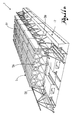
- FIG. 1 shows a plan view of the module of figure 1 in a reduced scale
- figure 3 shows a cross section of a portion of a floor constructed with the prefabricated modules of figure 1;
- figure 4 shows the cross section of a variation of the prefabricated module of figure 1;
- FIG. 5 shows a cross section of a portion of a floor constructed with the prefabricated modules of figure 4;
- FIG. - figure 6 shows the cross section view of a prefabricated module for constructing floors according to a second embodiment of the invention
- figure 7 shows the cross section of a variation of the prefabricated module of figure 6;
- FIG. 8 shows the cross section view of a prefabricated module for constructing floors according to a third embodiment of the invention
- figure 9 shows the cross section of a variation of the prefabricated module of figure 8.
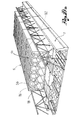
- Figures 1-3 show a prefabricated module 1 intended for being associated to other identical prefabricated modules 1 for constructing a floor.
- Said prefabricated module 1 comprises a trimmed joist 2, for example of brick material, with constant cross section, which exhibits a lower flat face 20 intended for defining the floor intrados, and an upper flat face 2 intended for defining the extrados.
- the trimmed joist 2 has a width comprised between 550 and 660 mm and a variable thickness, with a minimum of about 70 mm.
- the body of the trimmed joist 2 is crossed by a plurality of empty longitudinal passages 22 with polygonal cross profile, typically rectangular or triangular or circular.
- Said longitudinal passages 22 develop by the entire length of the trimmed joist 2 and are evenly distributed so as to leave a grating of solid walls having substantially the same thickness.
- the thickness of such walls is equal to about 10 mm.
- the longitudinal passages 22 impart a typical cell-like to the trimmed joist that relieves the overall weight, while increasing the heat insulation and soundproofing properties.
- the trimmed joist 2 has an indefinite length that can vary according to the requirements.
- joist 2 of the desired length.
- it consists of a plurality of identical brick segments of predetermined length, which are aligned in a row and reciprocally sided up to obtain the trimmed joist 2 of the desired length.
- each of said segments is comprised between 300 and 400 mm.
- the upper face 21 of the trimmed joist 2 exhibits three different recesses.
- Said recesses defines as many longitudinal grooves with constant cross profile that develop by the entire length of the trimmed joist 2, of which a central groove 23 and two identical side grooves 24 located symmetrical at opposite sides relative to the central one 23.
- the cross profile of the central groove 23 exhibits the shape of an isosceles trapezium, with the larger base at the upper face 21 and the side walls inclined by about 45° relative to the bases.
- the central groove 23 has as maximum depth equal to about 35 mm and a width at the inlet equal to about 200 mm.
- An undercut appendix 25 with substantially triangular cross section protrudes from each side wall of the central groove 23, which develops buy the entire length of the trimmed joist 2.
- the undercut appendices 25 are arranged in the proximity of the inlet of the central groove 23, and are reciprocally symmetrical relative to a vertical plane passing by the centre line of the central groove 23 itself.
- each undercut appendix 25 exhibits a lower side that with the relative inclined wall makes a dihedron of about 90°, and an upper side that is substantially parallel to the upper face 21 of the trimmed joist 2.
- the side grooves 24 exhibit a generally rectangular cross profile.
- they Preferably, they have a depth at about 35 mm and length equal to about 100 mm.
- Each side groove 24 features two undercut appendices 26 with trapezoidal cross section, which protrude from a respective side wall and develop by the entire length of the trimmed joist 2.
- said undercut appendices 26 are arranged in the proximity of the inlet of the side groove 24, and are reciprocally symmetrical relative to a vertical plane passing by the centre line of groove 24 itself.
- each side groove 24 there is seated a respective metal stiffening reinforcement, globally indicated with reference numeral 6.
- said metal reinforcement 6 comprises a steel bar 60 extending by the entire length of the trimmed joist 2, which is laid down at the centre of the side groove 24 and is oriented according to the longitudinal development of the same.
- Said steel bar 60 is sized for effectively supporting all the operating loads the prefabricated module 1 is subject to when it is laid.
- the metal reinforcement 6 further comprises a trestle 61 consisting of three parallel rods 62 arranged in the space at the vertices of a triangle and that are reciprocally connected by a reticular structure 63.
- Said trestle 61 develops by the entire length of the trimmed joist 2 and is oriented so that rods 62 are parallel to the longitudinal development of the relative side passage 24.
- first rods 62 are seated inside the side passage 24, whereas the third rod 62 is positioned outside, at a higher height than face 21 del of the trimmed joist 2.
- Rods 62 seated in the side passage 24 are individually positioned underneath a respective undercut appendix 26, so as to prevent the separation in vertical direction of trestle 61 relative to the trimmed joist 2.
- the metal reinforcement 6 described above is anchored by a finishing concrete casting 7 that during the construction of the prefabricated module 1, is cast inside the side passage 24 that serves as form.
- finishing casting 7 fills the side passage 24 flush with the upper face 21 of the trimmed joist 2.
- a concrete casting 4 is also cast in the central groove 23.
- finishing casting 4 fills the central groove 23 flush with the upper face 21 of the trimmed joist 2.
- the presence of the undercut projections 25 ensures that after hardening, the finishing casting 4 is always strongly clinging to the brick joist 2.
- said further stiffening reinforcement comprises two parallel metal rods 3 reciprocally spaced, which are positioned inside the central groove 23 oriented parallel to the longitudinal development of the latter.
- a lightening element 5 which surmounts the central groove 23 and delimits an air space 50 with longitudinal development that extends substantially by the entire length of the trimmed joist 2.
- said lightening element 5 consists of a body in thin plastic material wall, which exhibits a channel shape with constant cross section with substantially trapezoidal shape.
- said channel body 5 has a maximum depth comprised between 90 mm and 200 mm according to the needs, and a maximum width equal to about 420 mm.
- the channel body 5 is oriented parallel to the central groove 23 and has the concavity thereof facing the upper face 21 of the trimmed joist 2.
- the channel body 5 provides an upper flat wall 51 and two sides with vertical development 52 that together with the upper surface 21 of the trimmed joist 2, fully delimit the above air space 50.
- the upper flat wall 51 exhibits a series of stiffening ribs 53 suitable for imparting greater resistance to the channel body 5.
- sides 52 are individually provided with a horizontal flat edge 54, bent outwards, which directly rests on the upper face 21 of the trimmed joist 2.
- the channel body 5 is provided with suitable anchoring means that are buried into the finishing casting 4 that fills the central groove 23, so as to be firmly fixed to the trimmed joist 2.
- said anchoring means comprise a plurality of protrusions 55 obtained in a monolith body with the channel body 5, which are reciprocally spaced and are aligned in the direction of the longitudinal development of the channel body 5 itself (see fig. 2).
- Each protrusion 55 is shaped as a conical impression that protrudes from the upper flat wall 51 of the channel body 5 and that develops inside the concavity of the latter up to plunge its free end into the finishing concrete casting 4.
- the channel body 5 is assembled during the construction of the prefabricated module 1, immediately after the cast of the concrete casting 4, so that the conical protrusions 55 plunge into the concrete while it is still fresh and after the hardening are inseparably anchored thereto.
- the channel body 5 must not be assembled during the laying of the prefabricated module 1, as it happens in the known systems, thus reducing the interventions of the operators with consequent advantages in terms of safety and construction times.
- the presence of the anchoring means ensures that the channel body 5 always maintains its correct position on the trimmed joist 2, both during transport and during the subsequent laying.
- the channel body 5 is modular and consists of a plurality of identical brick segments of predetermined length, which are aligned in a row and connected to one another by special joints up to reach the desired overall length.
- each modular segment has a length preferably equal to about 720 mm.
- the top flat wall 51 of the channel body 51 is at a lower height than the protruding end of trestles 61 that are seated in the side grooves 24.
- the prefabricated modules 1 can be effectively piled on top of one another without the risk of damaging the channel body 5, favouring both storage and transport.
- the trestles in any case, for the elements shown in figures 1, 2, 3, 4 and 5 it is also possible for the trestles to have lower height than that of the channel body 5.
- the brick joists 2 of the prefabricated modules 1 are mounted and fixed on a special platform suitable for supporting the weight of the floor, and are moved one next to the other so as to make a continuous slab (see fig. 3).
- said slab is covered with a cast of fresh concrete that fully covers both the protruding portions of trestles 61 and the lightening channel bodies 5, leaving only air spaces 50 empty.
- the trimmed joist 2 has side edges 8 perfectly square, so as to fully abut against the side edges 8 of the adjacent brick joists 2.
- the trimmed joist 2 on the other hand exhibits side edges 8' provided with a flared upper portion.
- a channel 80 is defined between two brick joists 2 that are reciprocally sided.
- said channel 80 is filled with the above fresh concrete, ensuring a more reliable connection of said prefabricated modules 1 (see fig. 5).
- Figure 6 shows a prefabricated module 100 according to a second embodiment of the invention.
- Said prefabricated module 100 differs from module 1 described above in that the cross section of the trimmed joist 2 exhibits an intermediate portion with increased thickness that defines a rise 9 of the upper face 21.
- Said rise 9 extends between the two side grooves 24 and provides an upper flat surface 90, on which the central groove 23 is obtained.
- the channel body 5 is arranged resting on said upper surface 90 of rise 9 and is anchored, according to the modes described above, to the finishing casting 4 that fills the central groove 23.
- Figure 7 shows the prefabricated module 100 wherein the side edges 8 of the trimmed joist 2 exhibit a flared upper portion.
- Figure 8 shows a prefabricated module 110 according to a third embodiment of the invention.
- Said prefabricated module 110 differs from module 1 in that the entire cross section of the trimmed joist 2 has an increased thickness, and in that the side grooves 24 have a depth increased by a quantity substantially equal to the increase of thickness.
- the distance that separates the bottom of the side grooves 24 from the lower face 20 of the trimmed joist 2 is substantially the same as prefabricated module 1, whereas the stiffness and the resistance of the trimmed joist 2 are effectively increased.
- figure 9 shows the prefabricated module 110 wherein the side edges 8 of the trimmed joist 2 exhibit a flared upper portion.
- the lightening element 5 is made of brick, for example as shown in figure 10a.
- the brick lightening element rests on the trimmed joist 2.
- the lightening element 5 exhibits empty longitudinal passages 56, which define a cell-like structure, useful for lightening the structure, while maintaining considerable stiffness.
- passages 56 are arranged at different heights, that is, superimposed to one another.
- surface 51 is provided with longitudinal channels 57 that configure it as a fret pattern.
- the lightening element 5 is made of polystyrene (figure 10b), fixed to the trimmed joist 2 by extensions that plunge into the finishing casting 4.
- surface 51 of the lightening element is smooth.
- the lightening element 51 is made of a plastic material (figure 10c).
- the trimmed joist 2 is made of mineralised wood (figures 11 a to 11 c).
Landscapes
- Engineering & Computer Science (AREA)
- Architecture (AREA)
- Physics & Mathematics (AREA)
- Electromagnetism (AREA)
- Civil Engineering (AREA)
- Structural Engineering (AREA)
- Floor Finish (AREA)
Applications Claiming Priority (1)
| Application Number | Priority Date | Filing Date | Title |
|---|---|---|---|
| ITRE20060124 ITRE20060124A1 (it) | 2006-10-18 | 2006-10-18 | Modulo prefabbricato per la costruzione di impalcati |
Publications (2)
| Publication Number | Publication Date |
|---|---|
| EP1916350A2 true EP1916350A2 (fr) | 2008-04-30 |
| EP1916350A3 EP1916350A3 (fr) | 2011-01-12 |
Family
ID=38910894
Family Applications (1)
| Application Number | Title | Priority Date | Filing Date |
|---|---|---|---|
| EP07112059A Withdrawn EP1916350A3 (fr) | 2006-10-18 | 2007-07-09 | Module préfabriqué pour la construction planchers |
Country Status (2)
| Country | Link |
|---|---|
| EP (1) | EP1916350A3 (fr) |
| IT (1) | ITRE20060124A1 (fr) |
Cited By (9)
| Publication number | Priority date | Publication date | Assignee | Title |
|---|---|---|---|---|
| ES2322424A1 (es) * | 2008-10-28 | 2009-06-19 | Somapre Hispania, S.L. | Procedimiento de fabricacion de un elemento constructivo premontado y autoportante. |
| ITMI20091542A1 (it) * | 2009-09-07 | 2011-03-08 | Demuro S R L | Struttura di solaio con elementi prefabbricati e metodo per la sua realizzazione. |
| ITBO20100014A1 (it) * | 2010-01-14 | 2011-07-15 | Schnell House Italia S R L | Pannello di armatura per cemento armato |
| ITMI20101140A1 (it) * | 2010-06-23 | 2011-12-24 | Vinci Srl Flli | Pignatta di solaio ed elemento modulare di solaio |
| ITTO20110754A1 (it) * | 2011-08-08 | 2013-02-09 | Ripa Bianca S P A | Trave prefabbricata e metodo per la realizzazione di un solaio |
| ITMI20120730A1 (it) * | 2012-05-02 | 2013-11-03 | Luscari Salvatore Lembo | Nuovo blocco o pannello auto-portante, a struttura alleggerita, in particolare per la realizzazione di solai in cemento armato da gettare in opera |
| CN104532998A (zh) * | 2014-12-30 | 2015-04-22 | 王睿敏 | 易于安装的叠合楼板及其施工方法 |
| CN116100669A (zh) * | 2022-11-16 | 2023-05-12 | 惠州市睿住住工科技有限公司 | 一种可对钢筋的角度进行定位调节的浇筑系统 |
| WO2026076788A1 (fr) * | 2024-10-10 | 2026-04-16 | 中建科工集团有限公司 | Coffrage de dalle de plancher nervuré |
Family Cites Families (4)
| Publication number | Priority date | Publication date | Assignee | Title |
|---|---|---|---|---|
| FR2452555A2 (fr) * | 1979-03-27 | 1980-10-24 | Cerib | Procede pour l'isolation de poutrelle en beton pour plancher et poutrelle obtenue |
| GB2077792B (en) * | 1980-03-22 | 1983-06-08 | Tinsley Building Prod Ltd | Casting reinforced concrete floors |
| IT1264998B1 (it) * | 1993-12-15 | 1996-10-17 | Florenzio Cappellato | Elemento di alleggerimento per solai e impalcati in conglomerato cementizio armato |
| ES1063390U (es) * | 2006-07-06 | 2006-10-16 | Ingenieria De Prefabricados S.L. | Prelosa mixta para forjados. |
-
2006
- 2006-10-18 IT ITRE20060124 patent/ITRE20060124A1/it unknown
-
2007
- 2007-07-09 EP EP07112059A patent/EP1916350A3/fr not_active Withdrawn
Cited By (12)
| Publication number | Priority date | Publication date | Assignee | Title |
|---|---|---|---|---|
| ES2322424A1 (es) * | 2008-10-28 | 2009-06-19 | Somapre Hispania, S.L. | Procedimiento de fabricacion de un elemento constructivo premontado y autoportante. |
| ES2322424B1 (es) * | 2008-10-28 | 2010-01-22 | Somapre Hispania, S.L. | Procedimiento de fabricacion de un elemento constructivo premontado y autoportante. |
| ITMI20091542A1 (it) * | 2009-09-07 | 2011-03-08 | Demuro S R L | Struttura di solaio con elementi prefabbricati e metodo per la sua realizzazione. |
| ITBO20100014A1 (it) * | 2010-01-14 | 2011-07-15 | Schnell House Italia S R L | Pannello di armatura per cemento armato |
| ITMI20101140A1 (it) * | 2010-06-23 | 2011-12-24 | Vinci Srl Flli | Pignatta di solaio ed elemento modulare di solaio |
| EP2400074A2 (fr) | 2010-06-23 | 2011-12-28 | F.LLI Vinci S.r.l. | Bloc de plancher et élément de plancher modulaire |
| EP2400074A3 (fr) * | 2010-06-23 | 2012-07-04 | F.LLI Vinci S.r.l. | Bloc de plancher et élément de plancher modulaire |
| ITTO20110754A1 (it) * | 2011-08-08 | 2013-02-09 | Ripa Bianca S P A | Trave prefabbricata e metodo per la realizzazione di un solaio |
| ITMI20120730A1 (it) * | 2012-05-02 | 2013-11-03 | Luscari Salvatore Lembo | Nuovo blocco o pannello auto-portante, a struttura alleggerita, in particolare per la realizzazione di solai in cemento armato da gettare in opera |
| CN104532998A (zh) * | 2014-12-30 | 2015-04-22 | 王睿敏 | 易于安装的叠合楼板及其施工方法 |
| CN116100669A (zh) * | 2022-11-16 | 2023-05-12 | 惠州市睿住住工科技有限公司 | 一种可对钢筋的角度进行定位调节的浇筑系统 |
| WO2026076788A1 (fr) * | 2024-10-10 | 2026-04-16 | 中建科工集团有限公司 | Coffrage de dalle de plancher nervuré |
Also Published As
| Publication number | Publication date |
|---|---|
| ITRE20060124A1 (it) | 2008-04-19 |
| EP1916350A3 (fr) | 2011-01-12 |
Similar Documents
| Publication | Publication Date | Title |
|---|---|---|
| EP1916350A2 (fr) | Module préfabriqué pour la construction planchers | |
| US8336276B2 (en) | Modular construction system and components and method | |
| CA2741405C (fr) | Systeme et elements de construction modulaires, et procedes connexes | |
| US5797230A (en) | Element for use in making a reinforced concrete structure with cavities, filler body for making such an element, and method of making a reinforced concrete structure with cavities | |
| CN103797197B (zh) | 预铸整体式墙与楼板的建筑结构 | |
| EP1325991B1 (fr) | Procédé de fabrication d'un plancher en béton et panneau de coffrage utilisé selon ce procédé | |
| US5930965A (en) | Insulated deck structure | |
| US5884442A (en) | Composite joist and concrete panel assembly | |
| WO2011021151A1 (fr) | Procédé et système de construction sur le terrain de structures civiles | |
| WO2014096980A1 (fr) | Coffrage | |
| WO2011137496A9 (fr) | Structures pour le bâtiment | |
| EA035317B1 (ru) | Пустотообразующий элемент несъёмной опалубки для железобетонных многопустотных плитных конструкций | |
| US20060059804A1 (en) | Components for use in large-scale concrete slab constructions | |
| CN101346521B (zh) | 模板 | |
| EP2340342B1 (fr) | Poutre de support pour coffrage de dalle de plancher | |
| CN112218993A (zh) | 加强间隔件 | |
| KR0171873B1 (ko) | 선시공되는 코아를 이용한 고층건축물의 시공방법 | |
| RU178522U1 (ru) | Сборно-монолитное перекрытие | |
| US9464437B1 (en) | Precast I-beam concrete panels | |
| KR20200075600A (ko) | 피씨 슬래브를 이용한 건축물의 전이층 시공방법 | |
| US20070175141A1 (en) | Apparatus and Method for Forming an Elevated Deck | |
| JP2644366B2 (ja) | 菱目床構築用型枠及び菱目床の構築方法 | |
| RU2104375C1 (ru) | Висячее перекрытие и способ его монтажа | |
| NL2038468B1 (en) | Floor element and floor, method for manufacturing a floor element | |
| KR101033261B1 (ko) | 곡면 콘크리트 구조체의 시공 방법 |
Legal Events
| Date | Code | Title | Description |
|---|---|---|---|
| PUAI | Public reference made under article 153(3) epc to a published international application that has entered the european phase |
Free format text: ORIGINAL CODE: 0009012 |
|
| AK | Designated contracting states |
Kind code of ref document: A2 Designated state(s): AT BE BG CH CY CZ DE DK EE ES FI FR GB GR HU IE IS IT LI LT LU LV MC MT NL PL PT RO SE SI SK TR |
|
| AX | Request for extension of the european patent |
Extension state: AL BA HR MK RS |
|
| PUAL | Search report despatched |
Free format text: ORIGINAL CODE: 0009013 |
|
| AK | Designated contracting states |
Kind code of ref document: A3 Designated state(s): AT BE BG CH CY CZ DE DK EE ES FI FR GB GR HU IE IS IT LI LT LU LV MC MT NL PL PT RO SE SI SK TR |
|
| AX | Request for extension of the european patent |
Extension state: AL BA HR MK RS |
|
| RIC1 | Information provided on ipc code assigned before grant |
Ipc: E04B 5/38 20060101ALI20101209BHEP Ipc: E04B 5/18 20060101AFI20080117BHEP |
|
| STAA | Information on the status of an ep patent application or granted ep patent |
Free format text: STATUS: THE APPLICATION IS DEEMED TO BE WITHDRAWN |
|
| 18D | Application deemed to be withdrawn |
Effective date: 20110201 |