EP1916440B1 - Composant de structure en matière synthétique thermoplastique renforcée en fibres - Google Patents
Composant de structure en matière synthétique thermoplastique renforcée en fibres Download PDFInfo
- Publication number
- EP1916440B1 EP1916440B1 EP07405317A EP07405317A EP1916440B1 EP 1916440 B1 EP1916440 B1 EP 1916440B1 EP 07405317 A EP07405317 A EP 07405317A EP 07405317 A EP07405317 A EP 07405317A EP 1916440 B1 EP1916440 B1 EP 1916440B1
- Authority
- EP
- European Patent Office
- Prior art keywords
- structural part
- deformation element
- deformation
- force
- part according
- Prior art date
- Legal status (The legal status is an assumption and is not a legal conclusion. Google has not performed a legal analysis and makes no representation as to the accuracy of the status listed.)
- Active
Links
Images





Classifications
-
- B—PERFORMING OPERATIONS; TRANSPORTING
- B60—VEHICLES IN GENERAL
- B60N—SEATS SPECIALLY ADAPTED FOR VEHICLES; VEHICLE PASSENGER ACCOMMODATION NOT OTHERWISE PROVIDED FOR
- B60N2/00—Seats specially adapted for vehicles; Arrangement or mounting of seats in vehicles
- B60N2/68—Seat frames
- B60N2/688—Particular seat belt attachment and guiding
-
- B—PERFORMING OPERATIONS; TRANSPORTING
- B60—VEHICLES IN GENERAL
- B60N—SEATS SPECIALLY ADAPTED FOR VEHICLES; VEHICLE PASSENGER ACCOMMODATION NOT OTHERWISE PROVIDED FOR
- B60N2/00—Seats specially adapted for vehicles; Arrangement or mounting of seats in vehicles
- B60N2/24—Seats specially adapted for vehicles; Arrangement or mounting of seats in vehicles for particular purposes or particular vehicles
- B60N2/42—Seats specially adapted for vehicles; Arrangement or mounting of seats in vehicles for particular purposes or particular vehicles the seat constructed to protect the occupant from the effect of abnormal g-forces, e.g. crash or safety seats
- B60N2/427—Seats or parts thereof displaced during a crash
- B60N2/42709—Seats or parts thereof displaced during a crash involving residual deformation or fracture of the structure
-
- B—PERFORMING OPERATIONS; TRANSPORTING
- B60—VEHICLES IN GENERAL
- B60N—SEATS SPECIALLY ADAPTED FOR VEHICLES; VEHICLE PASSENGER ACCOMMODATION NOT OTHERWISE PROVIDED FOR
- B60N2/00—Seats specially adapted for vehicles; Arrangement or mounting of seats in vehicles
- B60N2/68—Seat frames
- B60N2/682—Joining means
-
- B—PERFORMING OPERATIONS; TRANSPORTING
- B60—VEHICLES IN GENERAL
- B60N—SEATS SPECIALLY ADAPTED FOR VEHICLES; VEHICLE PASSENGER ACCOMMODATION NOT OTHERWISE PROVIDED FOR
- B60N2/00—Seats specially adapted for vehicles; Arrangement or mounting of seats in vehicles
- B60N2/68—Seat frames
- B60N2/686—Panel like structures
-
- F—MECHANICAL ENGINEERING; LIGHTING; HEATING; WEAPONS; BLASTING
- F16—ENGINEERING ELEMENTS AND UNITS; GENERAL MEASURES FOR PRODUCING AND MAINTAINING EFFECTIVE FUNCTIONING OF MACHINES OR INSTALLATIONS; THERMAL INSULATION IN GENERAL
- F16F—SPRINGS; SHOCK-ABSORBERS; MEANS FOR DAMPING VIBRATION
- F16F7/00—Vibration-dampers; Shock-absorbers
- F16F7/12—Vibration-dampers; Shock-absorbers using plastic deformation of members
- F16F7/124—Vibration-dampers; Shock-absorbers using plastic deformation of members characterised by their special construction from fibre-reinforced plastics
Definitions
- the invention relates to a structural component of fiber-reinforced thermoplastic material according to the preamble of claim 1, which can be used for supporting functions in various applications.
- Such structural components may include fiber reinforcements of various types. Particularly favorable properties, with high strength at low weight for lightweight applications, include thermoplastic structural members with continuous fiber reinforcements containing endless fiber strands. From the WO99 / 52703 and the WO2004 / 024424 For example, those structural components are known which have a long-fiber-reinforced thermoplastic matrix with an integrated continuous fiber reinforcement made of endless fiber strands or with continuous fiber strands shaped endless fiber profiles. Such structural components, which can absorb loads and are especially suitable for vehicle construction, are used, for example, as seat structures, seats, rear seat backrests, door structures, etc. of vehicles.
- Fiber-reinforced structural components also still have important limitations, especially when structural components in vehicles are exposed to large impact loads and these in particular must pass various crash tests and load tests. Fiber-reinforced structural components usually have relatively limited elongations at break of, for example, 2 to 3%, while heavier metallic components may in some cases have significantly higher elongations at break. If, for example, crash loads have to be recorded in crash tests which are above the elastic limit of these fiber-reinforced structural components or over their ultimate loads, then irreversible damage occurs and above all there is a risk that the structural components will break and thus completely lose their functionality.
- Object of the present invention is therefore to provide simple means of lightweight fiber-reinforced structural components, which can absorb shock loads much better with lower irreversible deformations and especially without breaking, so that their functionality is better preserved and all requirements of stress tests and crash tests are met can. In this case, all occurring forces must be recorded with different directions at the load receiving points of the structural component.
- the lightweight fiber-reinforced structural components are combined with an integrated continuous fiber strand and with a compact, relatively small and light metallic deformation element, which is integrated at a load receiving point in the structural component and wherein the continuous fiber strand extends to the force introduction point to the deformation element.
- the dependent claims relate to advantageous developments of the invention with respect to optimum training, design and dimensioning of the deformation elements, matched to the structural components. This results in lightweight, easy to produce structural components, which can meet high load requirements and also a variety of crash tests with very different conditions and which are particularly suitable for means of transport and as components with load-bearing functions in vehicle construction.
- Fig. 1 schematically shows an inventive structural component 1 made of fiber-reinforced thermoplastic material with a relatively small, compact metallic deformation element 10.
- the structural component with at least one integrated continuous fiber strand 5 is connected to load receiving points A1, A2 with a support structure 2, for example in a vehicle.
- the deformation element 10 is connected on the one hand at a force introduction point 11 with the structural component 1 and on the other hand at a connection point 12 with the support structure 2 - here at the load receiving point A1.
- An integrated continuous fiber strand 5 extends up to the force introduction point 11, so that forces acting on the structural component are directed in a concentrated manner to these force introduction points 11 and a direct force transmission from the endless fiber strand 5 to the deformation element 10 can take place (see also FIG Fig. 2 ).
- the deformation element 10 is preferably arranged at a load receiving point A, where particularly strong loads or large force peaks F11 (t) occur when a shock load L (t) acts on the structural component.
- the deformation element is made of metal, eg of steel, it is relatively small and compact, so that it requires little space and weighs little and it is so dimensioned, shaped and designed that it undergoes a plastic irreversible deformation over a deformation path s10, if by a shock load L (t), which acts on the structural component, at the force introduction point 11, a force F11 (t) is generated, which is greater than a threshold value W.
- This threshold value W is selected, or the deformation element 10 is dimensioned and designed such that a defined maximum impact load Lmax is absorbed without breaking the structural component and the impact energy EL is partially degraded by plastic deformation energy Ep10 of the deformation element 10, so that after a occurred maximum impact load Lmax, eg according to crash test requirements, the structural component 1 can still take up a residual force and the required functionality is maintained.
- the relationships between the threshold value W, the forces F10, F1, F11 and the deformation path s10 are among the Fig. 4a - c further explained.
- a strong reduction in the maximum force F11max ( Fig. 5 ) can be achieved with a deformation element, which is designed with its threshold value W so that at an acting defined maximum impact load Lmax the plastic deformation energy Ep10 of the deformation element is at least 10% of the joint energy EL.
- a significant reduction in the maximum force peaks F11max is already possible if the deformation energy Ep10 is only a few percent of the impact energy EL.
- Fig. 2a, b show a deformation element 10 in two side views: Fig. 2a in section from the front and Fig. 2b from the side, here without the support structure 2.
- Suitable deformation elements may consist of a metal with high elongation at break (eg of suitable steel), which corresponds to at least 2 to 3 times the breaking elongation of the structural component 1 and which is for example at least 5%.
- This deformation element of Fig. 2 consists of a shaped bent sheet steel, which is connected at the force introduction point 11, for example by screwing, fixed to the structural component 1 and the integrated continuous fiber strand 5 and which is firmly connected to the connection point 12, which is a load receiving point A, with the support structure 2 is.
- This deformation element can thus be designed as a separate, replaceable element. Due to the load with a shock load L (t) and the resulting force F11 (t) at the point 11 is the Deformation element via a path s10 (t) deformed in the deformed layer 11d.
- the deformation path s10 of the deformation element can take place spatially with respect both to translation (sx, sy, sz) and to rotation (rx, ry, rz). This is very important, since in the case of real impact loads, for example in crash tests, the resulting forces occurring at the force introduction point 11 not only run in a constant direction, but also occur in varying directions along the deformation path and thereby also changing bending moments.
- the deformation element 10 is therefore preferably shaped and designed so that it can accommodate at least one translational and one rotational plastic deformation (see Fig. 9a, b ).
- the deformation element is designed in its shape and dimensioning so that corresponding to the occurring forces F11 (t) optimal deformation or an optimal deformation path s10 (x, y, z) is achieved and that thereby given boundary conditions with respect to geometric limitations of the deformation path, with respect Force curve F (s10) and allowable maximum loads F11max are adhered to the structural component, as will be explained further below.
- a sufficiently free space with a distance a for the deformation movements of the deformation element 10 must be provided between the structural component 1 and the support structure 2.
- the deformation elements 10 can be connected directly or indirectly to the force introduction point 11 in various ways with the structural component 1 and can also be permanently integrated.
- the resulting irreversible plastic deformation 18 after heavy loading of the structural component 1 can be measured, for example, with a gauge.
- the deformation element can thus be designed as an indicator which indicates this plastic deformation 18, or the deformation path s10. After a heavy load, the deformation element can thus indicate how strongly this load has acted on the structural component 1 and from this it can be deduced how strongly irreversible Damage to the structural component (such as fiber breaks and micro-cracks in the interior of the structural component) resulted. Accordingly, then the deformation element 10 or in the case of severe damage and the entire structural component 1 can be replaced.
- Fig. 2 shows a structural component with an endless fiber strand 5, which is firmly connected to the force introduction point 11 with the deformation element 10.
- the continuous fiber reinforcement 5 is here integrated in a shaping long fiber reinforced mass 4 (as well as in the examples of Fig. 8 . 10 . 11, 12 ).
- the Fig. 3a, b show examples of different force curves F10 (s10) of deformation elements 10 as a function of the deformation path s10.
- the deformation path is limited to a value s10max, for example by a stop or in which the force F10 (s10) increases rapidly here, but the breaking force F10br of the deformation element is designed to be higher than the breaking force F1br of the structural component 1 measured at the force introduction point 11 ( Fig. 4 ).
- the force-displacement curve F10 (s10) increases under elastic deformation Ee up to a threshold value W (corresponding to a elastic limit value EG10), whereupon a plastic deformation Ep takes place and the force-distance curve in the central region is substantially constant or slightly rising according to curve F10.1 ,
- the force-displacement curve F10 (s10) can also have regions with higher values 15 and lower values 16: For example, according to curve F10.2 with a higher threshold value W2 first higher values (with greater deformation resistance ) and then lower values (with a smaller deformation resistance). F10 (s10) can then gradually increase according to curve F10.3 with a lower threshold value W3 (16, 15).
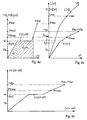
- Fig. 4a, b, c show at the force introduction point 11 schematically force curves F (s) as a function of the deformation paths s of a deformation element 10, a structural component 1 without deformation element and a structural component 1 with the deformation element 10, which the representation of Fig. 1 correspond.
- Fig. 4a shows the force curve F10 (s10) of a deformation element 10 as a function of the deformation path s10 at the force introduction point 11.
- F10 rises to a threshold value W, the elastic deformation energy Ee10 of the deformation element 10 being absorbed by the deformation element 10.
- This is followed by a plastic deformation with the plastic deformation energy Ep10 up to a value F10max which corresponds to a maximum load Lmax ( Fig. 4b ), which is exerted on the associated structural component 1 as a shock load L (t) (see Fig. 1 ).
- Fig. 4b shows the force curve F1 (s1) at the point 11 as a function of the deformation path s1, measured in the middle of a structural component 1 (according to FIG Fig. 1 ), here without an associated deformation element 10.
- the force F1 (s1) increases linearly in the elastic range up to a value Feg1 which corresponds to the elastic limit EG1 of the structural component 1.
- plastic deformation slowly sets in and the curve runs flatter up to a value F1max, which corresponds to the maximum load Lmax.
- the threshold value W of the deformation element 10 is smaller than the breaking force F1br of the structural component alone and also as the breaking force F11br of the structural component with deformation element 10.
- the breaking force F10br of the deformation element 10 is at least as great as the breaking force F1br of the structural component. So that the deformation element does not break.
- the threshold value W can amount to at most 60% -70% of the breaking force F1br of the structural component, so that the deformation element can perform its function optimally.
- the threshold value W may preferably also be 100% -150% of the force Feg1, which corresponds to the elastic limit value EG1 of the structural component 1.
- Fig. 4b the course of the shock load L (s1) is shown, which in the example of Fig. 1 engages in the middle of the structural component 1 (with the same distance d to A1 and A2).
- the force F1 (s1) at position 11 resulting from L (s1) is then half the size of the load L (s1) measured in the center of the structural component 1.
- the threshold value W should preferably be significantly greater than a maximum operating force Fd occurring at the force introduction point 11 during normal operation of a structural component. Thus, no plastic deformations, neither at the deformation element 10 nor at the structural component 1, should occur in normal operation.
- Fig. 4c are the representations of Fig. 4a and 4b or the force profiles of the deformation element F10 (s10) and the structural component F1 (s1) shown assembled.
- Fig. 4c shows at the point 11 the force curve F11 (s1 + s10) of the structural component 1 with deformation element 10 as a function of the deformation paths: s1 + s10 (where s10 is measured at the point 11 and s1 in the middle of the structural component 1).
- Fig. 5 shows at the point 11 schematically force curves F1 (t) and F11 (t) of a structural component 1 without and with deformation element 10 as a function of time t.
- These force curves correspond, for example, to a front crash test on a rear seat back according to Fig. 10 with different defined impact loads L (t), which correspond to a maximum total load with the maximum force values F1max and F11max of the structural component without and with deformation element 10.
- the breaking forces F1br of the structural component without and F11br with deformation element are essentially the same size.
- the force F1 (t) of the structural member without deformation element shows a shallow rise up to a value Feg1 corresponding to the elastic limit EG1 of the structural member.
- the curve F1 (t) rises sharply to the breaking force F1br and theoretically further up to a high value F1max, after which it drops again.
- the breaking force value F1br however, the rear seat backrest breaks apart without a deformation element, so that the crash load requirements can not be met without a deformation element.
- the threshold value W is selected such that, for a defined maximum impact load Lmax, the maximum occurring force F11max is at most 80% - better still at most 60% for higher requirements - of the maximum occurring force F1max at the force introduction point 11 without a deformation element 10.
- Fig. 6 shows similar to the example of Fig. 5 a calculation example of force curves F1 (t) and F11 (t) of a structural component without and with deformation element as a function of time.
- a relatively large effect ie a strong reduction of the maximum force F11max compared to F1max is achieved.
- the curves are similar to in Fig.
- F1 (t) rises more sharply and then again very steeply up to the maximum force F1max of, for example, 70 kN, then F1 (t) drops rapidly, but subsequently (approximately 100 ms after the beginning of the burst) a relative significant ringing with about 20 kN can be done.
- the force curve with deformation element F11 (t) again shows a strong reduction of the maximum force F11max to about 45 kN. This is well below the breaking forces F1br and F11br of about 55 kN.
- the structural component with deformation element does not break, the crash test requirements and the remaining functionality of the rear seat backrest are met.
- a great advantage and surprising effect of the invention is that with relatively little effort, with minimal space requirements, minimum cost and weight of the metallic deformation element 10 and by the concentrated power transmission with the continuous fiber strand 5 on the force introduction point 11 a great effect before In all, a strong reduction of the peak load F11max is achieved.
- the entire structural component 1 can be dimensioned much easier and with the inventive structural component including deformation element both weight and cost can be significantly reduced.
- Fig. 7a, b show examples of metallic deformation elements 10 with a possible deformation path s10 (x, y, z), wherein the force introduction point 11 is spatially displaced relative to the fixed connection point 12 in the layer 11d.
- Fig. 7a shows a slotted plate 14 as a deformation element and
- Fig. 7b shows a wavy curved sheet 13, which allows a particularly large deformation path s10.
- the desired force curves F10 (s10) such as Fig. 3 are explained are generated by the shaping and dimensioning of the deformation elements 10.
- the Fig. 8a, b show a further advantageous embodiment of the invention with a positive connection 17 between an endless fiber strand of the structural component and the deformation element at the force introduction point 11.
- the continuous fiber strand 5.3 and the deformation element 10.3 at the force introduction point 11 both a matching form-locking formation 17 -
- the deformation element 10.3 is also formally adapted to the here obliquely running endless fiber strand 5.3 for the purpose of optimal introduction of force.
- This deformation element 10.3 could, for example, on a seat lock 27 in the example of Fig. 10a be used.
- Fig. 8a shows the deformation element from above and Fig. 8b in a section A - A.
- Fig. 9a, b further illustrate the various possible deformation forces and moments which occur at the force introduction point 11 and which act on the deformation element 10 via the deformation path s10 and correspondingly deform it three-dimensionally.
- Fig. 9a shows as a simplified example an effect of a shock load on a structural component 1 in the main direction x, which generates a translational displacement of the force introduction point 11 into the position 11d at the force introduction point 11. Since the structural component itself is also deformed (bent) and displaced, the force introduction point 11 is also rotated, here with a rotation rz about the z-axis. Therefore, in most cases, the deformation element must be designed so that it can accommodate a translational and a rotational plastic deformation.
- Fig. 9b shows an example which, in addition to the rotation rz, has further rotatory deformations rx, ry about the spatial axes x, y. This is shown with the deformed deformation element 10d and the position and orientation of the force introduction point 11d with sx, sy, sz and rx, ry, rz. It is therefore very important that the metallic deformation element can accommodate translations and rotations three-dimensionally according to the respective requirements.
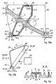
- Fig. 10a, b, c show a 2/3 rear seat back 24 of a vehicle as an example of a novel structural component with deformation elements, which must meet particularly high requirements, eg according to crash tests according to American regulations USNCAP or European ECE regulations.
- Such structural components must have continuous fiber reinforcements 5 included.
- they can contain at least two endless fiber strands 5.1, 5.2, which are connected in a force-transmitting manner to a long-fiber-reinforced connection region 6.
- the endless fiber strands can be formed as flat continuous fiber profiles with a horizontal continuous fiber profile 5.1 and a vertically oriented to this end fiber profile 5.2, which are interconnected at a spatial intersection point 7.
- deformation elements 10.1, 10.2, 10.3 can be used.
- a deformation element 10.1, 10.2, 10.3 can be arranged on a central axle mount 26, on an outer axle mount 34 or on a seat lock 27 or deformation elements can be arranged on two or all three load receiving points A1, A2, A3 according to requirements and boundary conditions.
- Fig. 10a shows the 2/3 rear seat back in plan
- Fig. 10b from the side
- Fig. 10c shows a cross section in the plane BB of Fig. 10a
- the rear seat back comprises three endless fiber strands or profiles 5.1, 5.2, 5.3, which are integrated into a shaping long fiber reinforced thermoplastic material 4, so that the loads occurring L and forces at the load receiving points A optimally absorbed, passed on and on the endless fiber strands the force application points 11 can be transferred concentrated on the deformation elements.
- a flat arranged continuous fiber profile 5.1 extends from a central axle bracket 26, which forms a load receiving point A1, to a seat lock 27 as a load receiving point A3.
- Two vertically oriented continuous fiber profiles 5.2, 5.3 extend from the load receiving point A2 (lateral axle holder) at a distance from one another to a belt connection 28.
- Fig. 10b illustrates the shock loads L1 and L2 occurring in a frontal crash Cf.
- the belt load L1 of a Passenger acts on a safety belt 25 and engages the buckle 28.
- Fig. 10c On average of Fig. 10c is the rigid, spatial structure evident with a flat continuous fiber profile 5.1 and the crossing vertical continuous fiber profiles 5.2, 5.3.
- the rear seat back has stiffening ribs 8 and 9 beads.
- Fig. 11 shows further examples of seat structures 20 as structural components, which may be formed as a seat, seat 21, seat back 22 or as a single seat structure 23.
- Fig. 11 shows a single seat structure with a structural component 1.1 as a seat back 22 and a structural component 1.2 as a seat 21.
- the seat shell 21 has two deformation elements 10.2, 10.3, which connect the seat with the support structure 2 at the points 11 and 12, here to the load receiving point A2, A3.
- a deformation element 10.1 is arranged between the two structural components 1.1 and 1.2 on a seat lock and hinge, which forms the load receiving point A1.
- the seat shell 21 forms the support structure for the seat back 22 here.
- the loads L1, L2 belt loads
- L3 seat load
- L4 baggage load occur.
- the loads L5 (of a passenger) and L6 (seat load) occur.
- the metallic deformation element may also be designed to accommodate more than one impact load L (t), e.g. for absorbing forces in different directions, from different load introduction points L and in different chronological order - e.g. also in a front crash and a subsequent rear crash.
- t more than one impact load L
- a structural component according to the invention can also be a tailgate of a vehicle with at least one integrated continuous fiber strand and a deformation element, e.g. on a hinge as a load receiving point.
Landscapes
- Engineering & Computer Science (AREA)
- Mechanical Engineering (AREA)
- Aviation & Aerospace Engineering (AREA)
- Transportation (AREA)
- General Engineering & Computer Science (AREA)
- Vibration Dampers (AREA)
- Laminated Bodies (AREA)
- Reinforced Plastic Materials (AREA)
Claims (26)
- Composant de structure (1) à base de plastique thermoplastique renforcé de fibre, comprenant au moins une corde à fibres continues (5), caractérisé par
un élément de déformation (10) métallique,
qui est relié d'une part en un point d'application de force (11) au composant de structure (1) et qui est relié d'autre part en un point de liaison (12) à une structure portante (2),
l'élément de déformation (10) subissant une déformation plastique par le biais d'une course de déformation (s10), lorsqu'une force F11(t), qui est supérieure à une valeur seuil (W), est générée au point d'application de force (11) par une charge de choc L(t) qui agit sur le composant de structure,
la valeur seuil(W) étant choisie de telle sorte qu'une charge de choc (Lmax) maximale définie soit interceptée sans rupture du composant de structure et que l'énergie de choc (EL) soit réduite partiellement par énergie de déformation plastique (Ep10) de l'élément de déformation (10),
et par une corde à fibres continues (5) allant jusqu'au point d'application de force (11). - Composant de structure selon la revendication 1, caractérisé en ce que la valeur seuil (W) est inférieure à la force de rupture (F1br) du composant de structure (1) sans élément de déformation (10) au point d'application de force (11) et la force de rupture (F10br) de l'élément de déformation (10) est au moins aussi grande que la force de rupture (F1br) du composant de structure sans élément de déformation.
- Composant de structure selon la revendication 1, caractérisé en ce que la valeur seuil (W) est choisie de telle sorte que, dans le cas d'une charge de choc (Lmax) maximale définie, la force (F11max) maximale apparaissant s'élève au maximum à 80 % de la force maximale (F1max) apparaissant au point d'application (11) sans élément de déformation (10).
- Composant de structure selon la revendication 1, caractérisé en ce que la valeur seuil (W) est choisie de telle sorte que, lors d'une charge de choc (Lmax) maximale définie agissant, l'énergie de déformation plastique (Ep10) de l'élément de déformation représente au moins 10 % de l'énergie de choc (EL).
- Composant de structure selon la revendication 1, caractérisé en ce que la valeur seuil (W) représente au maximum 70 % de la force de rupture (F1br) du composant de structure (1).
- Composant de structure selon la revendication 1, caractérisé en ce que la valeur seuil (W) représente 100 à 150 % de la force (Feg1) qui correspond à une valeur limite d'élasticité (EG1) du composant de structure (1).
- Composant de structure selon la revendication 1, caractérisé en ce que la valeur seuil (W) est supérieure à une force de service (Fd) maximale définie au point d'application de force (11).
- Composant de structure selon la revendication 1, caractérisé en ce que la course de déformation (s10) de l'élément de déformation est limitée (s10max).
- Composant de structure selon la revendication 1, caractérisé en ce que l'élément de déformation (10) peut absorber une déformation plastique par translation et une déformation plastique par rotation.
- Composant de structure selon la revendication 1, caractérisé en ce que la déformation (s10) de l'élément de déformation (10) par rapport à la translation et à la rotation s'effectue dans l'espace (x, y, z).
- Composant de structure selon la revendication 1, caractérisé en ce que l'élément de déformation présente une courbe force-course F10(s10) qui est sensiblement constante dans une zone (F10.1) centrale.
- Composant de structure selon la revendication 1, caractérisé en ce que l'élément de déformation présente une courbe force-course F10(s10) qui présente des zones avec des valeurs supérieures (15) et des valeurs inférieures (16) (F10.2, F10.3).
- Composant de structure selon la revendication 1, caractérisé en ce qu'une corde à fibres continues (5) et l'élément de déformation (10) présentent une déformation (17) par complémentarité de formes au point d'application de force (11).
- Composant de structure selon la revendication 1, caractérisé en ce que l'élément de déformation est conçu comme indicateur (18), une déformation résiduelle (s10) pouvant être constatée de façon simple et/ou étant conçue comme élément remplaçable séparé.
- Composant de structure selon la revendication 1, caractérisé en ce qu'il est prévu plus d'un élément de déformation (10.1, 10.2).
- Composant de structure selon la revendication 1, caractérisé en ce qu'il est prévu un élément de déformation entre deux composants de structure (1.1, 1.2).
- Composant de structure selon la revendication 1, caractérisé en ce qu'entre le composant de structure (1) et la structure portante (2) est prévu un espace libre avec un espacement (a) pour les mouvements de déformation de l'élément de déformation (10).
- Composant de structure selon la revendication 1, caractérisé en ce que l'élément de déformation (10) présente un allongement à la rupture qui correspond à au moins le double ou le triple de l'allongement à la rupture du composant de structure (1).
- Composant de structure selon la revendication 1, caractérisé en ce que l'élément de déformation (10) est conçu sous forme de tôle (14) pliée ou fendue ou avec une forme ondulée (13).
- Composant de structure selon la revendication 1, caractérisé en ce qu'au moins une corde à fibres continues (5) va d'un point d'application de force (11) d'un élément de déformation (10) en un premier point de suspension de charge (A1) jusqu'à un autre point de suspension de charge (A2) éloigné et/ou jusqu'à un point d'application de charge (L).
- Composant de structure selon la revendication 1, caractérisé en ce qu'au moins deux cordes à fibres continues (5.1, 5.2) sont prévues et sont reliées par transmission de force à une zone de liaison (6) renforcée de fibre longue.
- Composant de structure selon la revendication 1, caractérisé par un profil à fibres continues (5.1) orienté à plat et un profil à fibres continues (5.2) orienté verticalement par rapport au premier, lesquels profils sont reliés l'un à l'autre en un point de croisement (7) dans l'espace.
- Composant de structure selon la revendication 1, caractérisé en ce que le composant de structure est conçu sous forme de structure de siège (20), de coque de siège (21), de banquette, de dossier de siège (22) ou de structure de siège individuel (23).
- Composant de structure selon la revendication 1, caractérisé en ce que le composant de structure est conçu sous forme de dossier de siège 2/3 (24) avec au moins un élément de déformation, qui est disposé sur un support d'axe (26) central et/ou sur une attache de siège (27).
- Composant de structure selon la revendication 1, caractérisé en ce que le composant de structure est conçu sous forme de structure de porte (30), un élément de déformation (10.1) étant disposé sur une serrure de porte (32) ou sur une charnière (10.2).
- Composant de structure selon la revendication 1, caractérisé en ce que l'élément de déformation (10) est conçu pour l'absorption de plus d'une charge de choc (L(t)).
Applications Claiming Priority (1)
| Application Number | Priority Date | Filing Date | Title |
|---|---|---|---|
| CH17122006 | 2006-10-28 |
Publications (3)
| Publication Number | Publication Date |
|---|---|
| EP1916440A2 EP1916440A2 (fr) | 2008-04-30 |
| EP1916440A3 EP1916440A3 (fr) | 2010-01-20 |
| EP1916440B1 true EP1916440B1 (fr) | 2011-03-30 |
Family
ID=37684773
Family Applications (1)
| Application Number | Title | Priority Date | Filing Date |
|---|---|---|---|
| EP07405317A Active EP1916440B1 (fr) | 2006-10-28 | 2007-10-28 | Composant de structure en matière synthétique thermoplastique renforcée en fibres |
Country Status (3)
| Country | Link |
|---|---|
| EP (1) | EP1916440B1 (fr) |
| AT (1) | ATE503943T1 (fr) |
| DE (1) | DE502007006829D1 (fr) |
Families Citing this family (8)
| Publication number | Priority date | Publication date | Assignee | Title |
|---|---|---|---|---|
| FR2941892B1 (fr) * | 2009-02-06 | 2015-04-17 | Peugeot Citroen Automobiles Sa | Porte de vehicule automobile comportant des renforts integres dans la peau exterieure en matiere thermoplastique de cette porte et son procede de fabrication |
| DE102009050841A1 (de) | 2009-10-20 | 2011-04-21 | Keiper Gmbh & Co. Kg | Rückenlehnenanbindung, insbesondere für eine Rücksitzanlage eines Kraftfahrzeugs |
| DE102009050842A1 (de) | 2009-10-20 | 2011-04-21 | Keiper Gmbh & Co. Kg | Halter für eine Rücksitzanlage eines Karftfahrzeugs |
| DE102009050839B4 (de) | 2009-10-20 | 2022-03-03 | Adient Luxembourg Holding S.À R.L. | Rückenlehne, insbesondere für eine Rücksitzanlage eines Kraftfahrzeugs |
| JP5690939B2 (ja) | 2010-09-10 | 2015-03-25 | ジョンソン・コントロールズ・ゲー・エム・ベー・ハー | シートバックの後壁を製造する方法 |
| US9010839B2 (en) | 2012-10-24 | 2015-04-21 | Sabic Global Technologies B.V. | Vehicle side door structure and method of making and using the same |
| DE102013214789B4 (de) * | 2013-07-29 | 2023-10-05 | Bayerische Motoren Werke Aktiengesellschaft | Kraftfahrzeug |
| DE102018130323B4 (de) | 2018-11-29 | 2020-06-10 | Brose Fahrzeugteile SE & Co. Kommanditgesellschaft, Coburg | Fahrzeugsitz |
Family Cites Families (5)
| Publication number | Priority date | Publication date | Assignee | Title |
|---|---|---|---|---|
| US5662376A (en) * | 1993-07-19 | 1997-09-02 | Erda, Inc. | Force dissipation seat pedestal |
| DE19616915C1 (de) * | 1996-04-27 | 1997-10-02 | Brose Fahrzeugteile | Vorrichtung zur Gurtkraftbegrenzung eines Gurtrückhaltesystems in einem Kraftfahrzeug |
| DE19718050A1 (de) | 1997-04-29 | 1998-11-05 | Bayerische Motoren Werke Ag | Energieabsorbierendes Kraftbegrenzungsteil |
| EP1071554B1 (fr) | 1998-04-15 | 2004-03-03 | RCC Regional Compact Car AG | Composant structure en thermoplastique renforce par des fibres |
| EP1581380B1 (fr) | 2002-09-15 | 2007-03-07 | Weber Technology AG | Element structurel en matiere thermoplastique renforcee par des fibres |
-
2007
- 2007-10-28 EP EP07405317A patent/EP1916440B1/fr active Active
- 2007-10-28 DE DE502007006829T patent/DE502007006829D1/de active Active
- 2007-10-28 AT AT07405317T patent/ATE503943T1/de active
Also Published As
| Publication number | Publication date |
|---|---|
| EP1916440A2 (fr) | 2008-04-30 |
| DE502007006829D1 (de) | 2011-05-12 |
| ATE503943T1 (de) | 2011-04-15 |
| EP1916440A3 (fr) | 2010-01-20 |
Similar Documents
| Publication | Publication Date | Title |
|---|---|---|
| DE19748970B4 (de) | Integrale Türinnenverstärkung | |
| EP2376300B1 (fr) | Bras latéral d'un véhicule automobile | |
| DE102014104838B4 (de) | Federbeindom | |
| EP1916440A2 (fr) | Composant de structure en matière synthétique thermoplastique renforcée en fibres | |
| DE102004061303B4 (de) | Motorhaube für ein Kraftfahrzeug | |
| DE10153025A1 (de) | Aufprallträger einer Fahrzeugkarosserie | |
| DE3039895A1 (de) | Kraftfahrzeugtuere | |
| DE102020127736A1 (de) | Stoßfängeranordnung | |
| WO2015172759A1 (fr) | Gâche pour serrure de porte de véhicule automobile | |
| DE102013215323A1 (de) | Befestigungselement für ein Karosserieteil und Befestigungssystem mit Befestigungselement | |
| WO2010069087A1 (fr) | Support flexible | |
| DE102013001028A1 (de) | Zwischenschale für eine Kraftfahrzeugtür, Verfahren zur Herstellung einer Zwischenschale und Tür für ein Kraftfahrzeug | |
| EP2472137B1 (fr) | Elément de ressort à lame et agencement de ressort à lame | |
| DE202017104333U1 (de) | Bremskraftverstärkereinrichtung mit einem verformbaren Aktuator | |
| DE102009048222A1 (de) | Fahrzeugschloss | |
| DE102021103740A1 (de) | Türsystem für eine Tür für ein Fahrzeug zum Schutz eines Fahrzeug-Insassen bei einem Seitencrash | |
| WO2014063838A1 (fr) | Élément structural, procédé de fabrication d'un élément structural et utilisation de l'élément structural comme dossier de siège | |
| DE102010001231B4 (de) | Struktureinrichtung für ein Fahrzeug | |
| DE102017211339A1 (de) | Bremskraftverstärkereinrichtung mit einem verformbaren Aktuator | |
| DE10202043A1 (de) | Verbundbauteil mit ebenem und gekröpftem Grundkörper | |
| EP2700554B1 (fr) | Dispositif de fixation en porte-à-faux d'un siège passager et procédé de fabrication d'un tel dispositif ainsi que caisse de voiture | |
| EP2407685B1 (fr) | Dispositif de recyclage d'énergie dans une chute de charge lors d'un crash et structure porteuse destinée à un véhicule | |
| DE102008023889B4 (de) | Lenkrad mit kräftemäßig entkoppelter Lenkradspeiche | |
| DE102018205809B4 (de) | Trägerelement zum Befestigen eines Innenverkleidungsteils an einem Bauteil eines Fahrzeugs. | |
| DE102011003574A1 (de) | Hohlprofil für einen Fahrzeugsitz und Verfahren zur Herstellung eines solchen Hohlprofils |
Legal Events
| Date | Code | Title | Description |
|---|---|---|---|
| PUAI | Public reference made under article 153(3) epc to a published international application that has entered the european phase |
Free format text: ORIGINAL CODE: 0009012 |
|
| AK | Designated contracting states |
Kind code of ref document: A2 Designated state(s): AT BE BG CH CY CZ DE DK EE ES FI FR GB GR HU IE IS IT LI LT LU LV MC MT NL PL PT RO SE SI SK TR |
|
| AX | Request for extension of the european patent |
Extension state: AL BA HR MK RS |
|
| PUAL | Search report despatched |
Free format text: ORIGINAL CODE: 0009013 |
|
| AK | Designated contracting states |
Kind code of ref document: A3 Designated state(s): AT BE BG CH CY CZ DE DK EE ES FI FR GB GR HU IE IS IT LI LT LU LV MC MT NL PL PT RO SE SI SK TR |
|
| AX | Request for extension of the european patent |
Extension state: AL BA HR MK RS |
|
| 17P | Request for examination filed |
Effective date: 20100708 |
|
| AKX | Designation fees paid |
Designated state(s): AT BE BG CH CY CZ DE DK EE ES FI FR GB GR HU IE IS IT LI LT LU LV MC MT NL PL PT RO SE SI SK TR |
|
| GRAP | Despatch of communication of intention to grant a patent |
Free format text: ORIGINAL CODE: EPIDOSNIGR1 |
|
| RIC1 | Information provided on ipc code assigned before grant |
Ipc: B60N 2/42 20060101ALI20100909BHEP Ipc: F16F 7/12 20060101AFI20100909BHEP |
|
| GRAS | Grant fee paid |
Free format text: ORIGINAL CODE: EPIDOSNIGR3 |
|
| GRAA | (expected) grant |
Free format text: ORIGINAL CODE: 0009210 |
|
| RAP1 | Party data changed (applicant data changed or rights of an application transferred) |
Owner name: WEBER AUTOMOTIVE AG-HOLDING |
|
| AK | Designated contracting states |
Kind code of ref document: B1 Designated state(s): AT BE BG CH CY CZ DE DK EE ES FI FR GB GR HU IE IS IT LI LT LU LV MC MT NL PL PT RO SE SI SK TR |
|
| REG | Reference to a national code |
Ref country code: GB Ref legal event code: FG4D Free format text: NOT ENGLISH |
|
| REG | Reference to a national code |
Ref country code: CH Ref legal event code: EP |
|
| REG | Reference to a national code |
Ref country code: IE Ref legal event code: FG4D |
|
| REF | Corresponds to: |
Ref document number: 502007006829 Country of ref document: DE Date of ref document: 20110512 Kind code of ref document: P |
|
| REG | Reference to a national code |
Ref country code: DE Ref legal event code: R096 Ref document number: 502007006829 Country of ref document: DE Effective date: 20110512 |
|
| REG | Reference to a national code |
Ref country code: NL Ref legal event code: VDEP Effective date: 20110330 |
|
| PG25 | Lapsed in a contracting state [announced via postgrant information from national office to epo] |
Ref country code: GR Free format text: LAPSE BECAUSE OF FAILURE TO SUBMIT A TRANSLATION OF THE DESCRIPTION OR TO PAY THE FEE WITHIN THE PRESCRIBED TIME-LIMIT Effective date: 20110701 Ref country code: SE Free format text: LAPSE BECAUSE OF FAILURE TO SUBMIT A TRANSLATION OF THE DESCRIPTION OR TO PAY THE FEE WITHIN THE PRESCRIBED TIME-LIMIT Effective date: 20110330 Ref country code: LV Free format text: LAPSE BECAUSE OF FAILURE TO SUBMIT A TRANSLATION OF THE DESCRIPTION OR TO PAY THE FEE WITHIN THE PRESCRIBED TIME-LIMIT Effective date: 20110330 Ref country code: LT Free format text: LAPSE BECAUSE OF FAILURE TO SUBMIT A TRANSLATION OF THE DESCRIPTION OR TO PAY THE FEE WITHIN THE PRESCRIBED TIME-LIMIT Effective date: 20110330 |
|
| LTIE | Lt: invalidation of european patent or patent extension |
Effective date: 20110330 |
|
| PG25 | Lapsed in a contracting state [announced via postgrant information from national office to epo] |
Ref country code: FI Free format text: LAPSE BECAUSE OF FAILURE TO SUBMIT A TRANSLATION OF THE DESCRIPTION OR TO PAY THE FEE WITHIN THE PRESCRIBED TIME-LIMIT Effective date: 20110330 Ref country code: SI Free format text: LAPSE BECAUSE OF FAILURE TO SUBMIT A TRANSLATION OF THE DESCRIPTION OR TO PAY THE FEE WITHIN THE PRESCRIBED TIME-LIMIT Effective date: 20110330 Ref country code: CY Free format text: LAPSE BECAUSE OF FAILURE TO SUBMIT A TRANSLATION OF THE DESCRIPTION OR TO PAY THE FEE WITHIN THE PRESCRIBED TIME-LIMIT Effective date: 20110330 |
|
| REG | Reference to a national code |
Ref country code: IE Ref legal event code: FD4D |
|
| PG25 | Lapsed in a contracting state [announced via postgrant information from national office to epo] |
Ref country code: PT Free format text: LAPSE BECAUSE OF FAILURE TO SUBMIT A TRANSLATION OF THE DESCRIPTION OR TO PAY THE FEE WITHIN THE PRESCRIBED TIME-LIMIT Effective date: 20110801 Ref country code: EE Free format text: LAPSE BECAUSE OF FAILURE TO SUBMIT A TRANSLATION OF THE DESCRIPTION OR TO PAY THE FEE WITHIN THE PRESCRIBED TIME-LIMIT Effective date: 20110330 |
|
| PG25 | Lapsed in a contracting state [announced via postgrant information from national office to epo] |
Ref country code: ES Free format text: LAPSE BECAUSE OF FAILURE TO SUBMIT A TRANSLATION OF THE DESCRIPTION OR TO PAY THE FEE WITHIN THE PRESCRIBED TIME-LIMIT Effective date: 20110711 Ref country code: RO Free format text: LAPSE BECAUSE OF FAILURE TO SUBMIT A TRANSLATION OF THE DESCRIPTION OR TO PAY THE FEE WITHIN THE PRESCRIBED TIME-LIMIT Effective date: 20110330 Ref country code: CZ Free format text: LAPSE BECAUSE OF FAILURE TO SUBMIT A TRANSLATION OF THE DESCRIPTION OR TO PAY THE FEE WITHIN THE PRESCRIBED TIME-LIMIT Effective date: 20110330 Ref country code: SK Free format text: LAPSE BECAUSE OF FAILURE TO SUBMIT A TRANSLATION OF THE DESCRIPTION OR TO PAY THE FEE WITHIN THE PRESCRIBED TIME-LIMIT Effective date: 20110330 Ref country code: IS Free format text: LAPSE BECAUSE OF FAILURE TO SUBMIT A TRANSLATION OF THE DESCRIPTION OR TO PAY THE FEE WITHIN THE PRESCRIBED TIME-LIMIT Effective date: 20110730 |
|
| PG25 | Lapsed in a contracting state [announced via postgrant information from national office to epo] |
Ref country code: NL Free format text: LAPSE BECAUSE OF FAILURE TO SUBMIT A TRANSLATION OF THE DESCRIPTION OR TO PAY THE FEE WITHIN THE PRESCRIBED TIME-LIMIT Effective date: 20110330 |
|
| PG25 | Lapsed in a contracting state [announced via postgrant information from national office to epo] |
Ref country code: IE Free format text: LAPSE BECAUSE OF FAILURE TO SUBMIT A TRANSLATION OF THE DESCRIPTION OR TO PAY THE FEE WITHIN THE PRESCRIBED TIME-LIMIT Effective date: 20110330 |
|
| PLBE | No opposition filed within time limit |
Free format text: ORIGINAL CODE: 0009261 |
|
| STAA | Information on the status of an ep patent application or granted ep patent |
Free format text: STATUS: NO OPPOSITION FILED WITHIN TIME LIMIT |
|
| PG25 | Lapsed in a contracting state [announced via postgrant information from national office to epo] |
Ref country code: PL Free format text: LAPSE BECAUSE OF FAILURE TO SUBMIT A TRANSLATION OF THE DESCRIPTION OR TO PAY THE FEE WITHIN THE PRESCRIBED TIME-LIMIT Effective date: 20110330 Ref country code: DK Free format text: LAPSE BECAUSE OF FAILURE TO SUBMIT A TRANSLATION OF THE DESCRIPTION OR TO PAY THE FEE WITHIN THE PRESCRIBED TIME-LIMIT Effective date: 20110330 |
|
| 26N | No opposition filed |
Effective date: 20120102 |
|
| REG | Reference to a national code |
Ref country code: DE Ref legal event code: R097 Ref document number: 502007006829 Country of ref document: DE Effective date: 20120102 |
|
| BERE | Be: lapsed |
Owner name: WEBER AUTOMOTIVE AG-HOLDING Effective date: 20111031 |
|
| PG25 | Lapsed in a contracting state [announced via postgrant information from national office to epo] |
Ref country code: IT Free format text: LAPSE BECAUSE OF FAILURE TO SUBMIT A TRANSLATION OF THE DESCRIPTION OR TO PAY THE FEE WITHIN THE PRESCRIBED TIME-LIMIT Effective date: 20110330 Ref country code: MC Free format text: LAPSE BECAUSE OF NON-PAYMENT OF DUE FEES Effective date: 20111031 |
|
| PG25 | Lapsed in a contracting state [announced via postgrant information from national office to epo] |
Ref country code: BE Free format text: LAPSE BECAUSE OF NON-PAYMENT OF DUE FEES Effective date: 20111031 |
|
| PG25 | Lapsed in a contracting state [announced via postgrant information from national office to epo] |
Ref country code: MT Free format text: LAPSE BECAUSE OF FAILURE TO SUBMIT A TRANSLATION OF THE DESCRIPTION OR TO PAY THE FEE WITHIN THE PRESCRIBED TIME-LIMIT Effective date: 20110330 |
|
| PG25 | Lapsed in a contracting state [announced via postgrant information from national office to epo] |
Ref country code: LU Free format text: LAPSE BECAUSE OF NON-PAYMENT OF DUE FEES Effective date: 20111028 |
|
| PG25 | Lapsed in a contracting state [announced via postgrant information from national office to epo] |
Ref country code: BG Free format text: LAPSE BECAUSE OF FAILURE TO SUBMIT A TRANSLATION OF THE DESCRIPTION OR TO PAY THE FEE WITHIN THE PRESCRIBED TIME-LIMIT Effective date: 20110630 |
|
| PG25 | Lapsed in a contracting state [announced via postgrant information from national office to epo] |
Ref country code: TR Free format text: LAPSE BECAUSE OF FAILURE TO SUBMIT A TRANSLATION OF THE DESCRIPTION OR TO PAY THE FEE WITHIN THE PRESCRIBED TIME-LIMIT Effective date: 20110330 |
|
| PG25 | Lapsed in a contracting state [announced via postgrant information from national office to epo] |
Ref country code: HU Free format text: LAPSE BECAUSE OF FAILURE TO SUBMIT A TRANSLATION OF THE DESCRIPTION OR TO PAY THE FEE WITHIN THE PRESCRIBED TIME-LIMIT Effective date: 20110330 |
|
| REG | Reference to a national code |
Ref country code: FR Ref legal event code: PLFP Year of fee payment: 9 |
|
| REG | Reference to a national code |
Ref country code: FR Ref legal event code: PLFP Year of fee payment: 10 |
|
| PGFP | Annual fee paid to national office [announced via postgrant information from national office to epo] |
Ref country code: CH Payment date: 20170109 Year of fee payment: 10 |
|
| REG | Reference to a national code |
Ref country code: FR Ref legal event code: PLFP Year of fee payment: 11 |
|
| REG | Reference to a national code |
Ref country code: CH Ref legal event code: PL |
|
| PG25 | Lapsed in a contracting state [announced via postgrant information from national office to epo] |
Ref country code: CH Free format text: LAPSE BECAUSE OF NON-PAYMENT OF DUE FEES Effective date: 20171031 Ref country code: LI Free format text: LAPSE BECAUSE OF NON-PAYMENT OF DUE FEES Effective date: 20171031 |
|
| REG | Reference to a national code |
Ref country code: FR Ref legal event code: PLFP Year of fee payment: 12 |
|
| PGFP | Annual fee paid to national office [announced via postgrant information from national office to epo] |
Ref country code: DE Payment date: 20251021 Year of fee payment: 19 |
|
| PGFP | Annual fee paid to national office [announced via postgrant information from national office to epo] |
Ref country code: GB Payment date: 20251022 Year of fee payment: 19 |
|
| PGFP | Annual fee paid to national office [announced via postgrant information from national office to epo] |
Ref country code: AT Payment date: 20251022 Year of fee payment: 19 |
|
| PGFP | Annual fee paid to national office [announced via postgrant information from national office to epo] |
Ref country code: FR Payment date: 20251029 Year of fee payment: 19 |