EP1581380B1 - Element structurel en matiere thermoplastique renforcee par des fibres - Google Patents
Element structurel en matiere thermoplastique renforcee par des fibres Download PDFInfo
- Publication number
- EP1581380B1 EP1581380B1 EP03794753A EP03794753A EP1581380B1 EP 1581380 B1 EP1581380 B1 EP 1581380B1 EP 03794753 A EP03794753 A EP 03794753A EP 03794753 A EP03794753 A EP 03794753A EP 1581380 B1 EP1581380 B1 EP 1581380B1
- Authority
- EP
- European Patent Office
- Prior art keywords
- profiles
- structural component
- lft
- component according
- profile
- Prior art date
- Legal status (The legal status is an assumption and is not a legal conclusion. Google has not performed a legal analysis and makes no representation as to the accuracy of the status listed.)
- Expired - Lifetime
Links
- 229920001169 thermoplastic Polymers 0.000 title description 4
- 239000004416 thermosoftening plastic Substances 0.000 title description 4
- 229920001431 Long-fiber-reinforced thermoplastic Polymers 0.000 claims abstract description 60
- 239000000835 fiber Substances 0.000 claims abstract description 33
- 230000002787 reinforcement Effects 0.000 claims abstract description 12
- 230000015572 biosynthetic process Effects 0.000 claims description 16
- 238000007493 shaping process Methods 0.000 claims description 15
- 230000005540 biological transmission Effects 0.000 claims description 13
- 239000012815 thermoplastic material Substances 0.000 claims description 3
- OKTJSMMVPCPJKN-UHFFFAOYSA-N Carbon Chemical compound [C] OKTJSMMVPCPJKN-UHFFFAOYSA-N 0.000 claims description 2
- 238000010521 absorption reaction Methods 0.000 claims description 2
- 229910052799 carbon Inorganic materials 0.000 claims description 2
- 241000531908 Aramides Species 0.000 claims 1
- 229920003235 aromatic polyamide Polymers 0.000 claims 1
- 239000011521 glass Substances 0.000 claims 1
- 238000004519 manufacturing process Methods 0.000 claims 1
- 238000000034 method Methods 0.000 claims 1
- 229920000642 polymer Polymers 0.000 claims 1
- 239000011324 bead Substances 0.000 description 19
- 238000005755 formation reaction Methods 0.000 description 17
- 238000005452 bending Methods 0.000 description 13
- 239000010410 layer Substances 0.000 description 5
- 239000011159 matrix material Substances 0.000 description 3
- -1 polypropylene Polymers 0.000 description 3
- 238000003825 pressing Methods 0.000 description 3
- 239000004952 Polyamide Substances 0.000 description 2
- 239000004743 Polypropylene Substances 0.000 description 2
- 230000006978 adaptation Effects 0.000 description 2
- 238000000418 atomic force spectrum Methods 0.000 description 2
- 230000006835 compression Effects 0.000 description 2
- 238000007906 compression Methods 0.000 description 2
- 239000007788 liquid Substances 0.000 description 2
- 229920002647 polyamide Polymers 0.000 description 2
- 229920001707 polybutylene terephthalate Polymers 0.000 description 2
- 229920000139 polyethylene terephthalate Polymers 0.000 description 2
- 239000005020 polyethylene terephthalate Substances 0.000 description 2
- 229920001155 polypropylene Polymers 0.000 description 2
- 230000007704 transition Effects 0.000 description 2
- ZOXJGFHDIHLPTG-UHFFFAOYSA-N Boron Chemical compound [B] ZOXJGFHDIHLPTG-UHFFFAOYSA-N 0.000 description 1
- 229920000049 Carbon (fiber) Polymers 0.000 description 1
- 229910000831 Steel Inorganic materials 0.000 description 1
- 238000004026 adhesive bonding Methods 0.000 description 1
- 229920006125 amorphous polymer Polymers 0.000 description 1
- 239000004760 aramid Substances 0.000 description 1
- 229920006231 aramid fiber Polymers 0.000 description 1
- 229910052796 boron Inorganic materials 0.000 description 1
- 239000004917 carbon fiber Substances 0.000 description 1
- 230000000295 complement effect Effects 0.000 description 1
- 150000001875 compounds Chemical class 0.000 description 1
- 238000010276 construction Methods 0.000 description 1
- 230000001419 dependent effect Effects 0.000 description 1
- 238000011161 development Methods 0.000 description 1
- 230000018109 developmental process Effects 0.000 description 1
- 238000009826 distribution Methods 0.000 description 1
- 239000004744 fabric Substances 0.000 description 1
- 239000003365 glass fiber Substances 0.000 description 1
- 239000000463 material Substances 0.000 description 1
- 239000000203 mixture Substances 0.000 description 1
- 238000000465 moulding Methods 0.000 description 1
- 230000003014 reinforcing effect Effects 0.000 description 1
- 229920006126 semicrystalline polymer Polymers 0.000 description 1
- 239000011265 semifinished product Substances 0.000 description 1
- 239000010959 steel Substances 0.000 description 1
- 238000003860 storage Methods 0.000 description 1
- 239000002344 surface layer Substances 0.000 description 1
- 238000003466 welding Methods 0.000 description 1
Images



Classifications
-
- B—PERFORMING OPERATIONS; TRANSPORTING
- B60—VEHICLES IN GENERAL
- B60N—SEATS SPECIALLY ADAPTED FOR VEHICLES; VEHICLE PASSENGER ACCOMMODATION NOT OTHERWISE PROVIDED FOR
- B60N2/00—Seats specially adapted for vehicles; Arrangement or mounting of seats in vehicles
- B60N2/68—Seat frames
- B60N2/686—Panel like structures
-
- B—PERFORMING OPERATIONS; TRANSPORTING
- B29—WORKING OF PLASTICS; WORKING OF SUBSTANCES IN A PLASTIC STATE IN GENERAL
- B29C—SHAPING OR JOINING OF PLASTICS; SHAPING OF MATERIAL IN A PLASTIC STATE, NOT OTHERWISE PROVIDED FOR; AFTER-TREATMENT OF THE SHAPED PRODUCTS, e.g. REPAIRING
- B29C70/00—Shaping composites, i.e. plastics material comprising reinforcements, fillers or preformed parts, e.g. inserts
- B29C70/04—Shaping composites, i.e. plastics material comprising reinforcements, fillers or preformed parts, e.g. inserts comprising reinforcements only, e.g. self-reinforcing plastics
- B29C70/06—Fibrous reinforcements only
- B29C70/08—Fibrous reinforcements only comprising combinations of different forms of fibrous reinforcements incorporated in matrix material, forming one or more layers, and with or without non-reinforced layers
- B29C70/081—Combinations of fibres of continuous or substantial length and short fibres
-
- B—PERFORMING OPERATIONS; TRANSPORTING
- B29—WORKING OF PLASTICS; WORKING OF SUBSTANCES IN A PLASTIC STATE IN GENERAL
- B29C—SHAPING OR JOINING OF PLASTICS; SHAPING OF MATERIAL IN A PLASTIC STATE, NOT OTHERWISE PROVIDED FOR; AFTER-TREATMENT OF THE SHAPED PRODUCTS, e.g. REPAIRING
- B29C70/00—Shaping composites, i.e. plastics material comprising reinforcements, fillers or preformed parts, e.g. inserts
- B29C70/04—Shaping composites, i.e. plastics material comprising reinforcements, fillers or preformed parts, e.g. inserts comprising reinforcements only, e.g. self-reinforcing plastics
- B29C70/06—Fibrous reinforcements only
- B29C70/10—Fibrous reinforcements only characterised by the structure of fibrous reinforcements, e.g. hollow fibres
- B29C70/16—Fibrous reinforcements only characterised by the structure of fibrous reinforcements, e.g. hollow fibres using fibres of substantial or continuous length
- B29C70/20—Fibrous reinforcements only characterised by the structure of fibrous reinforcements, e.g. hollow fibres using fibres of substantial or continuous length oriented in a single direction, e.g. roofing or other parallel fibres
- B29C70/205—Fibrous reinforcements only characterised by the structure of fibrous reinforcements, e.g. hollow fibres using fibres of substantial or continuous length oriented in a single direction, e.g. roofing or other parallel fibres the structure being shaped to form a three-dimensional configuration
-
- B—PERFORMING OPERATIONS; TRANSPORTING
- B29—WORKING OF PLASTICS; WORKING OF SUBSTANCES IN A PLASTIC STATE IN GENERAL
- B29C—SHAPING OR JOINING OF PLASTICS; SHAPING OF MATERIAL IN A PLASTIC STATE, NOT OTHERWISE PROVIDED FOR; AFTER-TREATMENT OF THE SHAPED PRODUCTS, e.g. REPAIRING
- B29C70/00—Shaping composites, i.e. plastics material comprising reinforcements, fillers or preformed parts, e.g. inserts
- B29C70/04—Shaping composites, i.e. plastics material comprising reinforcements, fillers or preformed parts, e.g. inserts comprising reinforcements only, e.g. self-reinforcing plastics
- B29C70/28—Shaping operations therefor
- B29C70/30—Shaping by lay-up, i.e. applying fibres, tape or broadsheet on a mould, former or core; Shaping by spray-up, i.e. spraying of fibres on a mould, former or core
- B29C70/34—Shaping by lay-up, i.e. applying fibres, tape or broadsheet on a mould, former or core; Shaping by spray-up, i.e. spraying of fibres on a mould, former or core and shaping or impregnating by compression, i.e. combined with compressing after the lay-up operation
-
- B—PERFORMING OPERATIONS; TRANSPORTING
- B29—WORKING OF PLASTICS; WORKING OF SUBSTANCES IN A PLASTIC STATE IN GENERAL
- B29C—SHAPING OR JOINING OF PLASTICS; SHAPING OF MATERIAL IN A PLASTIC STATE, NOT OTHERWISE PROVIDED FOR; AFTER-TREATMENT OF THE SHAPED PRODUCTS, e.g. REPAIRING
- B29C70/00—Shaping composites, i.e. plastics material comprising reinforcements, fillers or preformed parts, e.g. inserts
- B29C70/04—Shaping composites, i.e. plastics material comprising reinforcements, fillers or preformed parts, e.g. inserts comprising reinforcements only, e.g. self-reinforcing plastics
- B29C70/28—Shaping operations therefor
- B29C70/40—Shaping or impregnating by compression not applied
- B29C70/42—Shaping or impregnating by compression not applied for producing articles of definite length, i.e. discrete articles
- B29C70/46—Shaping or impregnating by compression not applied for producing articles of definite length, i.e. discrete articles using matched moulds, e.g. for deforming sheet moulding compounds [SMC] or prepregs
-
- B—PERFORMING OPERATIONS; TRANSPORTING
- B29—WORKING OF PLASTICS; WORKING OF SUBSTANCES IN A PLASTIC STATE IN GENERAL
- B29D—PRODUCING PARTICULAR ARTICLES FROM PLASTICS OR FROM SUBSTANCES IN A PLASTIC STATE
- B29D99/00—Subject matter not provided for in other groups of this subclass
- B29D99/001—Producing wall or panel-like structures, e.g. for hulls, fuselages, or buildings
- B29D99/0014—Producing wall or panel-like structures, e.g. for hulls, fuselages, or buildings provided with ridges or ribs, e.g. joined ribs
-
- B—PERFORMING OPERATIONS; TRANSPORTING
- B60—VEHICLES IN GENERAL
- B60J—WINDOWS, WINDSCREENS, NON-FIXED ROOFS, DOORS, OR SIMILAR DEVICES FOR VEHICLES; REMOVABLE EXTERNAL PROTECTIVE COVERINGS SPECIALLY ADAPTED FOR VEHICLES
- B60J5/00—Doors
- B60J5/04—Doors arranged at the vehicle sides
- B60J5/042—Reinforcement elements
- B60J5/0422—Elongated type elements, e.g. beams, cables, belts or wires
- B60J5/0438—Elongated type elements, e.g. beams, cables, belts or wires characterised by the type of elongated elements
- B60J5/0443—Beams
- B60J5/0448—Beams with branched structures
-
- B—PERFORMING OPERATIONS; TRANSPORTING
- B60—VEHICLES IN GENERAL
- B60J—WINDOWS, WINDSCREENS, NON-FIXED ROOFS, DOORS, OR SIMILAR DEVICES FOR VEHICLES; REMOVABLE EXTERNAL PROTECTIVE COVERINGS SPECIALLY ADAPTED FOR VEHICLES
- B60J5/00—Doors
- B60J5/04—Doors arranged at the vehicle sides
- B60J5/048—Doors arranged at the vehicle sides characterised by the material
- B60J5/0481—Doors arranged at the vehicle sides characterised by the material plastic
-
- B—PERFORMING OPERATIONS; TRANSPORTING
- B60—VEHICLES IN GENERAL
- B60N—SEATS SPECIALLY ADAPTED FOR VEHICLES; VEHICLE PASSENGER ACCOMMODATION NOT OTHERWISE PROVIDED FOR
- B60N2/00—Seats specially adapted for vehicles; Arrangement or mounting of seats in vehicles
- B60N2/68—Seat frames
-
- B—PERFORMING OPERATIONS; TRANSPORTING
- B60—VEHICLES IN GENERAL
- B60N—SEATS SPECIALLY ADAPTED FOR VEHICLES; VEHICLE PASSENGER ACCOMMODATION NOT OTHERWISE PROVIDED FOR
- B60N2/00—Seats specially adapted for vehicles; Arrangement or mounting of seats in vehicles
- B60N2/68—Seat frames
- B60N2/682—Joining means
-
- Y—GENERAL TAGGING OF NEW TECHNOLOGICAL DEVELOPMENTS; GENERAL TAGGING OF CROSS-SECTIONAL TECHNOLOGIES SPANNING OVER SEVERAL SECTIONS OF THE IPC; TECHNICAL SUBJECTS COVERED BY FORMER USPC CROSS-REFERENCE ART COLLECTIONS [XRACs] AND DIGESTS
- Y10—TECHNICAL SUBJECTS COVERED BY FORMER USPC
- Y10T—TECHNICAL SUBJECTS COVERED BY FORMER US CLASSIFICATION
- Y10T428/00—Stock material or miscellaneous articles
- Y10T428/24—Structurally defined web or sheet [e.g., overall dimension, etc.]
- Y10T428/24058—Structurally defined web or sheet [e.g., overall dimension, etc.] including grain, strips, or filamentary elements in respective layers or components in angular relation
- Y10T428/24124—Fibers
Definitions
- the invention relates to a structural component made of long-fiber-reinforced thermoplastic with integrated continuous fiber reinforcements according to the preamble of claim 1.
- Such known structural components usually have continuous-area endless fiber reinforcements, e.g. with fabric semi-finished products or with sandwich construction, which, however, are very limited in terms of possible shapes and applications.
- Structural components with integrated endless fiber strands have also become known.
- WO99 / 52703 discloses a structural component having a shape-forming long-fiber-reinforced thermoplastic matrix and having an integrated support structure made of endless fiber strands. In this case, the endless fiber strands are interconnected by flat joints. However, this only results in simple, flat support structures and no spatially formed continuous fiber reinforcement structures for optimal recording and transmission of three-dimensional attacking loads and forces.
- a structural component according to claim 1 with an integrated three-dimensional crossing point, which is formed from a plurality of individual shaped continuous filament (EF) profiles in a long fiber-thermoplastic (LFT) composition.
- EF continuous filament
- LFT long fiber-thermoplastic
- the dependent claims relate to advantageous developments of the invention regarding optimal three-dimensional design of the continuous fiber reinforcement structure and applicability in a variety of applications with optimal mechanical properties for receiving loads in any direction.
- the component consists of a LFT mass 6 (made of long-fiber reinforced thermoplastic) with an endless fiber (EF) reinforcement consisting of a plurality of individual, integrated and defined shaped EFs -Profiles 10, which are formed according to the male forces and loads and arranged individually accurately positioned in the component.
- the three-dimensional crossing point 50 has an upper and a lower main plane H1, H2 at a vertical distance v. It is formed by at least three EF profiles which converge at the intersection or intersect, and by the LFT mass 6 connecting all these profiles.
- At least one EF profile in the upper main plane H1 (here the profile 10.1 ) and an EF profile lie in the lower main level H2 (here the profile 10.4).
- At least one further EF profile here the profiles 10.2 and 10.3, with a vertical orientation, or an extension in the vertical direction, must go through to support a moment M2.
- All EF profiles are at the intersection by the LFT mass 6 force-transmitting connected to each other (UB) by corresponding formations 32 of the LFT mass, or by mutual formal vote successive of EF profiles and LFT mass.
- the EF profiles 10.1, 10.4 lie in a bead 7 and the EF profiles 10.2 and 10.3 in ribs 8.
- forces F, moments M and loads L acting on a structural component in different directions taken by the EF profiles and transmitted at the spatial intersection 50.
- moments at the intersection can be transferred from one profile pair to the other.
- the EF profiles 10.1 and 10.4 with the bead 7 form a bending beam and the profile pairs 10.2 and 10.3 in the rib structure 8 form a second bending beam.
- the moments M1 and M2 are recorded and transmitted.
- a significant advantage of this inventive arrangement of the EF profiles at the spatial crossing point is that it consists of a component and does not have to be assembled from several components.
- the EF profiles can be inserted successively or together in an LFT mold and then with an introduced, molten LFT mass in an LFT press in one step and be pressed into a one-piece component.
- the storage order is as follows: First, the EF profile 10.1 is placed in the lower main level H2, then the EF profiles 10.2 and 10.3 in the vertical intermediate area v and then the EF profile 10.4 in the upper main level H1 and then the molten LFT Mass placed on it and pressed with the EF profiles.
- This Fig. 1a shows a component which has been reversed after pressing in the LFT tool, so that H1 below and H2 are in the figure above. So the EF profiles are clearly visible.
- the direction in which the EF profiles 10 and the LFT mass 6 are inserted is indicated by an arrow.
- FIGS. 1b, 1c show two sections through a further example of a three-dimensional intersection 50 with two EF profiles 10.3, 10.4 in the upper main plane H1, an EF profile 10.1 in the lower main plane H2 and an EF profile 10.2 in a rib 8 in the vertical area v between them.
- the EF profiles 10.1, 10.3, 10.4 lie in a bead 7, which crosses the rib 8.
- the position of the component is shown here as it is in the LFT tool.
- Fig. 1b shows the cross section through the bead 7, (which receives the moment M1)
- Fig. 1c shows the cross section through the rib 8, (which receives the moment M2).
- the LFT mass For optimum transmission of EF profiles 10 to the LFT mass 6 and from an EF profile (10.1) via the LFT mass to other EF profiles (10.3, 10.4), the LFT mass has connecting formations 32.
- the arrangement of the EF profiles and the formations 32 of the LFT mass create the desired force transmission UB at the spatial intersection 50.
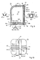
- Fig. 2 shows another example of a spatial intersection in a component which is designed as a curved shell.
- the main planes H1 and H2 here form tangent planes at the intersection 50.
- the given possible vertical distance v between H 1 and H2 is relatively small here for reasons of space.
- the flat EF profiles 10.1 and 10.3 intersecting EF profile 10.2 have a reduced height in the area v at the intersection point, for example with a square cross-section a, and pass again into a flat, vertically oriented cross-section b next to the intersection 50.
- the EF profiles have a vertical extension in the v-area for the purpose of torque transmission. That is, the EF-profiles 10 may have a basically any three-dimensional shape and position, which is optimally adapted to the load conditions and the force curves.
- FIGS. 3a, b, c schematically illustrate various possible types of three-dimensional crossing points.
- Demanding structural components must be able to absorb and pass on several loads L, forces F and moments M which act on different parts of the component and in different directions.
- the three-dimensional intersections 50 according to the invention can be designed in this way, for example, by "X", "T” or “L” -shaped configurations by means of corresponding arrangements of the EF profiles.
- FIG. 3 a shows an "X" -shaped intersection with load receptacles at the points L 1 to L 4 and with the power transmissions U B at the intersection 50.
- Fig. 3b shows a "T" -shaped intersection with load pickups at the points L1, L2, L3 and with the power transmissions UB at the intersection.
- Fig. 3c shows an "L" -shaped crossing point with the load shots L1, L2, L3 and at the point L2 also with the power transmissions UB at the intersection.
- FIGS. 4, 5 show examples of moment load lever structures formed by the arrangement of the EF profiles with the intersection 50.
- Fig. 4 shows a moment-load lever structure with a "T" - or "X" -shaped crossing point 50.
- a force + F is supported as a main load direction and recorded by an EF profile 10.2 as a vertically oriented profile v, eg in one Rib, between two horizontal EF profiles 10.1 in the lower main level H2 and 10.3 in the upper main level H1.
- the force F results in a moment M, which are supported by the EF profiles 10.1, 10.3 in a suitable shape of the LFT tool, for example in a bead.
- Fig. 5 shows an "L" -shaped moment-load lever structure which supports as main load directions the forces + F, -F (i.e., in both directions). In turn, it contains a vertically oriented profile 10.2 in the region v, which is supported by three EF profiles, e.g. on a bead and in the main planes: the EF profile 10.1 in H2 and the EF profiles 10.3 and 10.4 in H1. In this way, the moments + M, -M resulting from the forces + F, -F are supported and relayed.
- the EF profiles correspond to the different functions and requirements at different points of an EF profile or component. They may have a three-dimensional shape and have in the longitudinal direction of a bend, rotation, folding and / or a surface structuring and they may have varying, different cross-sectional shapes.
- FIGS. 7a, 7b illustrate an example of an EF profile 10 that has different cross-sectional shapes over its length, in adaptation to the forces to be transmitted and for optimum connection to the LFT mass 6.
- the figures show an EF profile in cross-section 10a, 10b in a rib 8, for example according to the profiles 10.2 or 10.3 of Fig. 8, at two different locations.
- Fig. 7a shows a shaping 10a with a positioning shoulder 55 for fixing and holding the EF profile in the desired position - especially during pressing, when the liquid LFT mass 6 is pressed into the rib.
- the EF profile has a thicker area 56 as tensile and compression zones (in the fiber longitudinal direction) for transmitting moments.
- the shear strength is increased by the adjacent LFT layer 6 with isotropic fiber distribution (while the strength transverse to the fiber direction in the EF profiles 10 is lower here).
- the profile cross-section 10b is changed correspondingly to the force ratios there: stretched, ie higher and narrower and without positioning shoulder.
- further positioning points 54 may be formed on the EF profiles corresponding to the formations of the LFT tool 310 (top) and 31 u (bottom ) correspond.
- Positioning can also be arranged distributed in the longitudinal direction of the EF profiles.
- such profile shapes can also be positioned and fixed on bead walls, for example on the two side walls of a bead 7 - instead of the two EF profiles (10.2, 10.3) in two separate ribs 8 as in the following example of FIG is shown.
- the cross-sections of EF profiles may, after application, for example, also be "L" or "Z" -shaped.
- 8a, b show the example of a complex structural component with a three-dimensional crossing point in the form of a two-thirds (2/3) rear seat back 74 with a Mittelgurtanitati 60 for the middle seat and a retaining lock 58 and with several demanding load applications for different load cases (crash loads).
- 8a shows a plan view of the arrangement of the EF profiles in the component
- FIG. 8b shows in perspective the LFT mass 6 and therein the integrated EF profiles 10.1 to 10.4.
- This example illustrates the load-optimized shape of the EF profiles themselves as well as the load-optimized arrangement to a structure with appropriate shaping of the LFT mass 6 and with optimal power transmission between the main load bearing EF profiles (with directional continuous fibers) and the complementary LFT mass (with undirected long fibers).
- the EF profile 10.1 has an arcuate widening 22 and an adapted LFT formation 32.1 for receiving a metallic insert 4 at the axle bearing 59a.
- the other axle bearing receptacle 59b is formed by formations 22.2 of the EF profiles 10.2 and 10.3 and connecting formations 32.2 of the LFT mass. These profile ends 22.2 are bent over and anchored in the LFT mass to increase the tensile strength.
- the lock 58 is screwed to a lock plate on the EF profile 10.3 and supported by the EF profile 10.2.
- the belt reel 60 is supported by formations 22 of the EF-profiles 10.1 and 10.4 and by LFT-formations 32.
- the smaller loads L8, L9 of headrests 61 are received here by LFT-formations 32. But it could also be an additional cross-laid EF profile 10.5 (partially flat and vertically aligned) are integrated for reinforcement.
- the shapes in the component may have special formations 22 for force transitions and for the direct absorption of external loads or for receiving inserts 4 (built-in components) to which external loads are introduced into the component.
- the shaping of the surrounding LFT mass 6 is also selected in accordance with the shaping of the EF profiles 10. Shapes of force transmissions (of forces and moments) inside a component (eg from an EF profile via the LFT mass to other EF profiles) can be formed both as formations 22 of the EF profiles and as formations 32 of the LFT mass be. In general, the most balanced, continuous transitions are formed to reduce strength and stiffness jumps between EF profiles and LFT mass.
- FIG. 9 shows a single seat back 72 with a belt connection 60 and head restraints 61 in which similar loads and load cases occur as in the example of FIG. 8, here with the main loads L1 on the belt connection 60 and L2 the weight of the passenger.
- all loads must be supported by the fixable axle brackets 59b, and possibly also 59a, about which the seat back is pivotally adjusted.
- the lock can be present on both sides on 59b and 59a or often only on one side on 59b.
- a profile carrier formed from EF profiles between the detent 59b and the belt connection 60 must be made particularly strong with increased torsional rigidity.
- a closed hollow profile cross section can be formed here (analogous to FIG. 12), for example with three EF profiles 10.1, 10.2, 10.3 in one Beading 7 of the component 1 and it can also be a separate cover member 1.2 with an EF profile 10.10 thermoplastic welded.
- the profile carrier between the Achshalterungen and detents 59a and 59b here has the EF profiles 10.4, 10.5, 10.6 in the main planes H1, H2 at a bead 7.
- the profile beam between the axle bracket 59a and the belt connector 60 is bent and has two vertical EF profiles 10.7, 10.8 e.g. in the side walls of a bead 7.
- Two spatial intersections 50 are formed here on the axle holders 59a and 59b.
- all EF profiles are integrated into beads, at the intersections of the EF profiles, the beads locally go into ribs, so that there is always a crossing point between a rib 8 and a bead 7 is formed and so that all EF profiles in can be stored one step and the structural component 1 can be pressed in one piece in one step.
- other arrangements of EF profiles in ribs and beads may be combined as needed.
- Fig. 10 shows an arrangement of EF-profiles with a spatial intersection 50 which can be used as a seat 76 or as a cabin floor, e.g. a lift cabin, is formed.
- a shell of relatively small thickness i. small vertical distance v between the main planes H1, H2, three vertical EF-profiles 10.2, 10.3, 10.4, v are integrated in a rib structure crossing two EF-profiles 10.1, 10.5 in the main planes H1, H2.
- the EF profiles 10.1 and 10.5 could also converge and be connected there directly to each other flatly. With the loads L2 - L4 (also L1) this structure is supported.
- Fig. 11 shows an example of a structural member constituting a supporting structure of a car door 78 with integrated side crash protection.
- the bending beam a connects the upper hinge 79a with the lock 80 and the bending beam b the lower hinge 79b with the lock 80, wherein this at the intersection 50 opens into the bending beam a and continues until the lock 80 (a + b).
- Fig. 12 shows an example of a structural member 82 which is multi-piece, e.g. bivalve, is composed, e.g. by welding or gluing.
- a structural component 1 with a crossing point is connected to another component 1.2, which forms a lid to an open bead, so that both components 1 and 1.2 together form a closed, tubular, EF-reinforced profile cross-section with particularly high torsional stiffness (as a variant in Fig. 9 is explained).
- Such two-part components are preferably welded together thermoplastic.
- the shaping of the vertically oriented EF profiles 10.2 and 10.3 in the sidewalls of the bead 7 may be e.g. also have a flat part, which is adapted to the EF profile 10.10 in the cover member 1.2. Behind these EF profiles 10.2, 10.3 could be e.g. with a transverse vertical EF profile 10.4 a spatial crossing point 50 are formed.
- the LFT mass 6 preferably has an average fiber length of at least 3 mm, better of 5 to 15 mm.
- the continuous fiber reinforcement (EF) of the EF profiles may consist of oriented glass, carbon or aramid fibers in the thermoplastic matrix (although in special cases boron fibers for maximum compressive strength or steel fibers would not be excluded).
- the EF profiles 10 may be composed mainly of DU (unidirectional) layers (0 °), but also of layers with different fiber orientation, eg alternately with layers of 0 ° / 90 ° or 0 ° / + 45 ° / - 45 ° fiber orientations. You can also make a thin one Surface layer (eg 0.1 - 0.2 mm) made of pure thermoplastic material without EF fiber reinforcement exhibit.
- semicrystalline polymers such as polypropylene (PP), polyethylene terephthalate (PET), polybutylene terephthalate (PBT) or polyamide (PA) as the matrix of EF profiles 10 and of LFT mass 6, e.g. because they can have higher compressive strengths.
- PP polypropylene
- PET polyethylene terephthalate
- PBT polybutylene terephthalate
- PA polyamide
Landscapes
- Engineering & Computer Science (AREA)
- Mechanical Engineering (AREA)
- Chemical & Material Sciences (AREA)
- Composite Materials (AREA)
- Aviation & Aerospace Engineering (AREA)
- Transportation (AREA)
- Textile Engineering (AREA)
- Architecture (AREA)
- Civil Engineering (AREA)
- Structural Engineering (AREA)
- Body Structure For Vehicles (AREA)
Abstract
Claims (20)
- Elément structurel (1) en matière thermoplastique renforcée par des fibres longues (LFT) avec renforts intégrés à filaments continus (EF),
caractérisé par- au moins trois profilés individuels moulés intégrés (10) à filaments continus (EF)- qui se rejoignent à un point d'intersection,- et qui forment un point d'intersection (50) conçu en trois dimensions dans l'espace,- au moins un profilé EF (10) se trouvant au point d'intersection dans un plan principal supérieur et dans un plan principal inférieur (H1, H2) du point d'intersection et un profilé EF s'étendant en continu avec une étendue verticale (v) entre ces profilés EF du plan principal supérieur et du plan principal inférieur- et les profilés EF (10) étant reliés les uns aux autres au point d'intersection (50) avec transmission de force par la masse LFT (6)- par des déformations correspondantes (32) de la masse LFT- et plusieurs forces (F) ou moments (M) pouvant être appuyés en plusieurs endroits sur les profilés EF (10) pour absorber les charges extérieures (L). - Elément structurel selon la revendication 1, caractérisé en ce que des introductions de forces extérieures (L) sont réalisées à l'aide de déformations LFT (32) et/ou avec des déformations de profilés EF appropriées (22).
- Elément structurel selon la revendication 1, caractérisé en ce que les points d'intersection (50) tridimensionnels sont conçus en forme de "X", de "T" ou de "L".
- Elément structurel selon la revendication 1, caractérisé en ce que les profilés EF au point d'intersection (50) sont disposés de telle manière que les profilés EF (10) peuvent être posés les uns après les autres ou les uns avec les autres dans un outil de formage LFT, puis comprimés avec une masse LFT fondue chargée (6) dans une presse LFT au cours d'une étape et pour former un élément monobloc.
- Elément structurel selon la revendication 1, caractérisé en ce que les profilés EF (10) sont constitués de couches avec des orientations de fibres différentes.
- Elément structurel selon la revendication 1, caractérisé en ce que la masse LFT (6') présente une longueur de fibre moyenne d'au moins 3 mm.
- Elément structurel selon la revendication 1, caractérisé en ce que les profilés EF (10) comportent un renfort par filaments continus (EF) en fibres de verre, de carbone ou d'aramide.
- Elément structurel selon la revendication 1, caractérisé en ce que la matière thermoplastique de la masse LFT (6) et des profilés EF (10) est constituée de polymères semi-cristallins tels que le PP, le PET, le PBT, le PA.
- Elément structurel selon la revendication 1, caractérisé en ce que les profilés EF (10) présentent un profilage tridimensionnel.
- Elément structurel selon la revendication 1, caractérisé en ce que les profilés EF (10.1 - 10.6) présentent une flexion, une torsion, un plissement et/ou une structuration de surface dans le sens longitudinal.
- Elément structurel selon la revendication 1, caractérisé en ce que les profilés EF (10) présentent des formes différentes en section transversale.
- Elément structurel selon la revendication 1, caractérisé en ce que des déformations (22) sont créées dans les profilés EF et des déformations (32) sont créées dans la masse LFT pour des introductions de forces et de transitions de force entre les profilés EF (10) et la masse LFT (6) ainsi vers les inserts (4).
- Elément structurel selon la revendication 1, caractérisé en ce qu'un profilé EF (10) est formé avec un épaulement de positionnement (55), une zone épaisse de traction et de pression en haut et en bas (56) ainsi qu'une zone de poussée plus mince (57) entre celles-ci et le profilé EF est positionné dans une nervure (8) ou dans une paroi à moulures (7) de l'élément structurel.
- Elément structurel selon la revendication 1, caractérisé en ce que les profilés EF (10) forment une "structure moment-levier de charge" avec un point d'intersection tridimensionnel en forme de "T" ou en forme de "L".
- Elément structurel selon la revendication 1, caractérisé en ce qu'il forme un dossier de siège individuel (72) avec attache de ceinture (60).
- Elément structurel selon la revendication 1, caractérisé en ce qu'il forme un dossier de siège arrière de deux-tiers (74) avec attache de ceinture (60) et serrure de blocage (58).
- Elément structurel selon la revendication 1, caractérisé en ce qu'il forme une coque de siège (76) ou un plancher de cabine.
- Elément structurel selon la revendication 1, caractérisé en ce qu'il forme une structure porteuse de porte d'automobile (78) avec une protection intégrée contre les chocs latéraux.
- Elément structurel selon la revendication 1, caractérisé en ce qu'il est constitué de plusieurs parties (82), par exemple de deux coques 1, 1.2.
- Procédé destiné à la fabrication d'un élément structurel selon la revendication 1, dans lequel
plusieurs profilés EF moulés (10) sont posés les uns après les autres ou les uns avec les autres dans un outil de formage LFT où ils sont positionnés dans une position prédéterminée pour former un point d'intersection (50) tridimensionnel, puis une masse LFT fondue (6) est chargée et comprimée avec les profilés EF (10) au cours d'une étape pour former un élément monobloc.
Applications Claiming Priority (3)
| Application Number | Priority Date | Filing Date | Title |
|---|---|---|---|
| CH15672002 | 2002-09-15 | ||
| CH156702 | 2002-09-15 | ||
| PCT/CH2003/000621 WO2004024424A1 (fr) | 2002-09-15 | 2003-09-15 | Element structurel en matiere thermoplastique renforcee par fibres |
Publications (2)
| Publication Number | Publication Date |
|---|---|
| EP1581380A1 EP1581380A1 (fr) | 2005-10-05 |
| EP1581380B1 true EP1581380B1 (fr) | 2007-03-07 |
Family
ID=31983668
Family Applications (1)
| Application Number | Title | Priority Date | Filing Date |
|---|---|---|---|
| EP03794753A Expired - Lifetime EP1581380B1 (fr) | 2002-09-15 | 2003-09-15 | Element structurel en matiere thermoplastique renforcee par des fibres |
Country Status (6)
| Country | Link |
|---|---|
| US (1) | US20060165955A1 (fr) |
| EP (1) | EP1581380B1 (fr) |
| CN (1) | CN1684822B (fr) |
| AU (1) | AU2003258443A1 (fr) |
| DE (1) | DE50306774D1 (fr) |
| WO (1) | WO2004024424A1 (fr) |
Cited By (5)
| Publication number | Priority date | Publication date | Assignee | Title |
|---|---|---|---|---|
| WO2014064572A1 (fr) | 2012-10-24 | 2014-05-01 | Sabic Innovative Plastics Ip B.V. | Structure de portière latérale de véhicule et procédé de fabrication et d'utilisation de cette dernière |
| EP2613970B1 (fr) | 2010-09-10 | 2016-05-11 | Johnson Controls GmbH | Procédé pour fabriquer une paroi arrière de dossier de siège |
| CN108416175A (zh) * | 2018-04-28 | 2018-08-17 | 吉林大学 | 长纤维复合材料乘用车后排座椅骨架初始材料设计方法 |
| EP4454853A1 (fr) * | 2023-04-24 | 2024-10-30 | Weber Fibertech GmbH | Composant structurel |
| DE102024107265A1 (de) * | 2024-03-14 | 2025-09-18 | Audi Aktiengesellschaft | Befestigungsstruktur zur Befestigung eines Fahrzeugsitzes |
Families Citing this family (50)
| Publication number | Priority date | Publication date | Assignee | Title |
|---|---|---|---|---|
| US7470388B2 (en) * | 2002-09-15 | 2008-12-30 | Weber Technology Ag | Method for the production of structural components from fiber-reinforced thermoplastic material |
| DE102006012699B4 (de) * | 2006-03-17 | 2011-05-05 | Johnson Controls Gmbh | Glasfaser verstärkte Struktur des Innenraums eines Kraftfahrzeuges |
| GB2439613B (en) | 2006-06-30 | 2008-08-27 | Motorola Inc | Processor, method and terminal for use in communications |
| EP1916440B1 (fr) | 2006-10-28 | 2011-03-30 | Weber Automotive AG-Holding | Composant de structure en matière synthétique thermoplastique renforcée en fibres |
| US20080277987A1 (en) * | 2007-05-11 | 2008-11-13 | Cutting Dynamics, Inc. | Composite seat back frame |
| FR2941892B1 (fr) * | 2009-02-06 | 2015-04-17 | Peugeot Citroen Automobiles Sa | Porte de vehicule automobile comportant des renforts integres dans la peau exterieure en matiere thermoplastique de cette porte et son procede de fabrication |
| DE102009039498A1 (de) * | 2009-07-06 | 2011-01-13 | Volkswagen Ag | Sitzschale eines Kraftfahrzeugs sowie Verfahren zur Herstellung einer Sitzschale eines Kraftfahrzeugs |
| JP5547290B2 (ja) * | 2009-09-22 | 2014-07-09 | ジョンソン・コントロールズ・ゲー・エム・ベー・ハー | 背もたれのための後壁を製造する方法 |
| US8158245B2 (en) * | 2009-09-24 | 2012-04-17 | Cytec Technology Corp. | Thermoplastic composites and methods of making and using same |
| DE102009050839B4 (de) | 2009-10-20 | 2022-03-03 | Adient Luxembourg Holding S.À R.L. | Rückenlehne, insbesondere für eine Rücksitzanlage eines Kraftfahrzeugs |
| DE102009053053B4 (de) * | 2009-11-16 | 2011-09-01 | Eads Deutschland Gmbh | Plattenförmiges Bauteil und Verfahren zur Herstellung eines plattenförmigen Bauteils |
| FR2952581B1 (fr) * | 2009-11-18 | 2012-01-06 | Daher Aerospace | Panneau en materiau composite |
| EP2504186B1 (fr) * | 2009-11-25 | 2013-09-25 | Weber Automotive AG-Holding | Hayon en plastique thermoplastique renforce par des fibres |
| US9238347B2 (en) | 2010-06-11 | 2016-01-19 | Ticona Llc | Structural member formed from a solid lineal profile |
| CA2800931A1 (fr) | 2010-06-22 | 2011-12-29 | Ticona Llc | Profiles creux renforces |
| RU2013102597A (ru) | 2010-06-22 | 2014-07-27 | ТИКОНА ЭлЭлСи | Способ изготовления армированных одноосно ориентированных профилей |
| KR20130088034A (ko) | 2010-06-22 | 2013-08-07 | 티코나 엘엘씨 | 연속 섬유 및 장섬유를 함유하는 열가소성 프리프레그 |
| EP2697043A1 (fr) | 2011-04-12 | 2014-02-19 | Ticona LLC | Tiges thermoplastiques renforcées par des fibres continues et procédé de pultrusion pour leur fabrication |
| CN103477020A (zh) | 2011-04-12 | 2013-12-25 | 提克纳有限责任公司 | 用于海底应用的脐带 |
| TW201308362A (zh) | 2011-04-12 | 2013-02-16 | Ticona Llc | 用於電子傳輸電纜之複合核心 |
| DE102011114742A1 (de) * | 2011-09-28 | 2013-03-28 | Keiper Gmbh & Co. Kg | Fahrzeugsitz, insbesondere Kraftfahrzeugsitz |
| EP2686158A1 (fr) * | 2012-03-23 | 2014-01-22 | Cutting Dynamics, Inc. | Ébauche composite renforcée par des fibres moulées à orifice de guidage |
| WO2013142798A1 (fr) * | 2012-03-23 | 2013-09-26 | Cutting Dynamics, Inc. | Élément de structure à assemblage par encliquetage |
| US20150044419A1 (en) * | 2012-03-23 | 2015-02-12 | Cutting Dynamics, Inc. | Composite structural component |
| EP2848461B1 (fr) * | 2012-05-11 | 2017-07-05 | Toray Industries, Inc. | Armature de coussin de siège pour véhicule |
| DE102012010768A1 (de) | 2012-05-31 | 2013-12-05 | Decoma (Germany) Gmbh | Strukturbauteil für ein Kraftfahrzeug |
| DE112013005095A5 (de) * | 2012-10-22 | 2015-07-23 | Johnson Controls Components Gmbh & Co. Kg | Strukturbauteil, Verfahren zur Herstellung eines Strukturbauteils und Verwendung des Strukturbauteils als Sitzlehne |
| DE102013214789B4 (de) * | 2013-07-29 | 2023-10-05 | Bayerische Motoren Werke Aktiengesellschaft | Kraftfahrzeug |
| FR3009705B1 (fr) * | 2013-08-13 | 2016-08-26 | Faurecia Bloc Avant | Doublure interieure renforcee de hayon, notamment pour vehicule automobile |
| DE102013223519A1 (de) * | 2013-11-19 | 2015-05-21 | Bayerische Motoren Werke Aktiengesellschaft | Faserkunststoffverbundbauteil und Verfahren zum Herstellen eines Faserkunststoffverbundbauteils, insbesondere eines Karosseriebauteils für ein Kraftfahrzeug |
| GB2511171A (en) * | 2013-12-12 | 2014-08-27 | Daimler Ag | Support structure for a vehicle, in particular a side door of a vehicle |
| EP2889212B1 (fr) | 2013-12-30 | 2016-01-06 | AIRBUS HELICOPTERS DEUTSCHLAND GmbH | Structure de sous-plancher avec une coque intégral pour un aéronef à voilure tournante |
| JP2015178241A (ja) * | 2014-03-19 | 2015-10-08 | トヨタ自動車株式会社 | 繊維強化樹脂材の製造方法 |
| KR101616634B1 (ko) * | 2014-09-24 | 2016-04-29 | (주)엘지하우시스 | 시트백 프레임, 이의 제조방법 및 차량용 시트백 |
| GB201419902D0 (en) * | 2014-11-07 | 2014-12-24 | Mclaren Automotive Ltd | Fibre-reinforced components |
| DE102014222933B4 (de) * | 2014-11-11 | 2021-09-09 | Bayerische Motoren Werke Aktiengesellschaft | Faserverbundwerkstoffbauteil sowie Verfahren zur Herstellung eines Faserverbundwerkstoffbauteils |
| DE102014224040A1 (de) * | 2014-11-25 | 2016-05-25 | Bayerische Motoren Werke Aktiengesellschaft | Verfahren zu Herstellung einer Strukturbauteilgruppe sowie Strukturbauteilgruppe |
| DE102015206962A1 (de) | 2015-04-17 | 2016-10-20 | Brose Fahrzeugteile Gmbh & Co. Kg, Coburg | Strukturbaugruppe für eine Fahrzeugsitz-Rückenlehne |
| CN104943191A (zh) * | 2015-04-30 | 2015-09-30 | 郑州翎羽新材料有限公司 | 一种高强度热塑性复合塑料漏粪板及其制备方法 |
| CN110290919A (zh) * | 2017-02-22 | 2019-09-27 | 三菱重工业株式会社 | 复合材料及复合材料的制造方法 |
| US10436307B2 (en) * | 2017-02-27 | 2019-10-08 | GM Global Technology Operations LLC | Composite axle housing and methods of manufacturing thereof |
| WO2018193611A1 (fr) | 2017-04-21 | 2018-10-25 | 日産自動車株式会社 | Structure de liaison pour éléments formés d'une résine renforcée par des fibres et procédé de production d'élément formé à partir d'une résine renforcée par des fibres |
| US20180345604A1 (en) | 2017-06-02 | 2018-12-06 | Arris Composites Llc | Aligned fiber reinforced molding |
| KR102200966B1 (ko) * | 2017-11-16 | 2021-01-11 | (주)엘지하우시스 | 차량용 시트백 프레임 및 그의 제조방법 |
| US10926489B2 (en) | 2018-07-12 | 2021-02-23 | Arris Composites Inc. | Methods and compositions for compression molding |
| WO2020123145A1 (fr) * | 2018-11-30 | 2020-06-18 | Arris Composites Inc. | Pièces composites renforcées par des fibres, moulées par compression et procédés de fabrication |
| CN109624877B (zh) * | 2018-12-10 | 2022-01-25 | 江苏华曼复合材料科技有限公司 | 一种lft板材的汽车底部护板及其生产方法 |
| WO2020148251A1 (fr) * | 2019-01-14 | 2020-07-23 | Adient Engineering and IP GmbH | Module de siège pour un siège de véhicule, procédé pour le montage d'un module de siège ainsi que siège de véhicule |
| US12257817B2 (en) * | 2019-03-29 | 2025-03-25 | Kawasaki Jukogyo Kabushiki Kaisha | Composite panel structure and method of manufacturing |
| US11945139B2 (en) * | 2020-08-14 | 2024-04-02 | Arris Composites Inc. | Method for composite truss manufacturing |
Family Cites Families (10)
| Publication number | Priority date | Publication date | Assignee | Title |
|---|---|---|---|---|
| FR2513176A1 (fr) * | 1981-09-18 | 1983-03-25 | Allibert Sa | Procede permettant d'enrober hermetiquement les armatures d'une piece en matiere plastique armee interieurement et pieces obtenues selon ce procede |
| DE3479572D1 (en) * | 1983-01-05 | 1989-10-05 | Deutsche Forsch Luft Raumfahrt | Element for joining of two bars with circular cross-section |
| US4573707A (en) * | 1984-01-30 | 1986-03-04 | Pabst Rudolf D | Composite lightweight non-metallic vehicle frame |
| US5704644A (en) * | 1993-02-27 | 1998-01-06 | Esoro Ag | Lightweight road vehicle with strengthening structure |
| US5900311A (en) * | 1994-03-23 | 1999-05-04 | Cook Composites And Polymers Co. | Thermosetting polyester composites prepared via vacuum-assisted technique with smooth surface appearance |
| JP3456301B2 (ja) * | 1995-03-30 | 2003-10-14 | チッソ株式会社 | 繊維および特定のカーボンブラックを均一に含有する繊維強化熱可塑性複合体 |
| WO1998015404A1 (fr) * | 1996-10-08 | 1998-04-16 | Rcc Regional Compact Car Ag | Piece moulee en plastique et structure de construction |
| EP1071554B1 (fr) * | 1998-04-15 | 2004-03-03 | RCC Regional Compact Car AG | Composant structure en thermoplastique renforce par des fibres |
| US6652796B1 (en) * | 1998-05-26 | 2003-11-25 | Kishimoto Sangyu Co Ltd | Method for manufacturing glass fiber-reinforced resin moldings |
| DE50004943D1 (de) * | 1999-10-20 | 2004-02-05 | Rcc Regional Compact Car Ag Ku | Fahrzeugzelle aus faserverstärktem thermoplastischem kunststoff |
-
2003
- 2003-09-15 EP EP03794753A patent/EP1581380B1/fr not_active Expired - Lifetime
- 2003-09-15 DE DE50306774T patent/DE50306774D1/de not_active Expired - Lifetime
- 2003-09-15 WO PCT/CH2003/000621 patent/WO2004024424A1/fr not_active Ceased
- 2003-09-15 CN CN03821717.1A patent/CN1684822B/zh not_active Expired - Lifetime
- 2003-09-15 AU AU2003258443A patent/AU2003258443A1/en not_active Abandoned
-
2005
- 2005-03-14 US US10/527,953 patent/US20060165955A1/en not_active Abandoned
Cited By (5)
| Publication number | Priority date | Publication date | Assignee | Title |
|---|---|---|---|---|
| EP2613970B1 (fr) | 2010-09-10 | 2016-05-11 | Johnson Controls GmbH | Procédé pour fabriquer une paroi arrière de dossier de siège |
| WO2014064572A1 (fr) | 2012-10-24 | 2014-05-01 | Sabic Innovative Plastics Ip B.V. | Structure de portière latérale de véhicule et procédé de fabrication et d'utilisation de cette dernière |
| CN108416175A (zh) * | 2018-04-28 | 2018-08-17 | 吉林大学 | 长纤维复合材料乘用车后排座椅骨架初始材料设计方法 |
| EP4454853A1 (fr) * | 2023-04-24 | 2024-10-30 | Weber Fibertech GmbH | Composant structurel |
| DE102024107265A1 (de) * | 2024-03-14 | 2025-09-18 | Audi Aktiengesellschaft | Befestigungsstruktur zur Befestigung eines Fahrzeugsitzes |
Also Published As
| Publication number | Publication date |
|---|---|
| CN1684822B (zh) | 2010-05-26 |
| AU2003258443A1 (en) | 2004-04-30 |
| US20060165955A1 (en) | 2006-07-27 |
| DE50306774D1 (de) | 2007-04-19 |
| WO2004024424A1 (fr) | 2004-03-25 |
| EP1581380A1 (fr) | 2005-10-05 |
| CN1684822A (zh) | 2005-10-19 |
Similar Documents
| Publication | Publication Date | Title |
|---|---|---|
| EP1581380A1 (fr) | Element structurel en matiere thermoplastique renforcee par fibres | |
| EP0683072B1 (fr) | Absorbeur d'énergie améliorant la sécurité dans l'habitacle des véhicules | |
| EP1224111B1 (fr) | Cellule de vehicule en matiere thermoplastique renforcee par des fibres | |
| DE69522950T3 (de) | Tragstruktur unter zugspannung | |
| EP1375310B1 (fr) | Structure de carosserie pour un véhicule, en particulier pour une automobile | |
| EP2480427B1 (fr) | Procédé de fabrication d'un dossier de siège | |
| DE19948363B4 (de) | Mittelsäulenstruktur | |
| DE19608127B9 (de) | Verfahren zum Herstellen eines Faserverbundbauteils | |
| EP1308265B1 (fr) | Pièce moulée allongée de matière composite renforcée par des fibres | |
| EP2976250B1 (fr) | Seuil de porte pour une carrosserie de véhicule | |
| WO1997043158A1 (fr) | Caisse de vehicule ferroviaire | |
| EP1058625B1 (fr) | Porte ou hayon arriere pour vehicule a moteur et son procede de fabrication | |
| EP2782811A1 (fr) | Élément léger pour carrosserie | |
| DE4208150A1 (de) | Rueckenlehne fuer einen fahrzeugsitz | |
| EP0298903A2 (fr) | Plaque de fond pour un véhicule à moteur | |
| EP0712777B1 (fr) | Châssis en matières synthétiques pour tondeuse à gazon | |
| DE19714631A1 (de) | Selbsttragende Kraftfahrzeugkarosserie | |
| EP1022164B1 (fr) | Dispositif d'attelage et crochet | |
| EP1916440B1 (fr) | Composant de structure en matière synthétique thermoplastique renforcée en fibres | |
| EP4263317B1 (fr) | Traverse pour un bogie et son procédé de production | |
| EP2520490B1 (fr) | Utilisation d'un composant léger | |
| EP2199148B1 (fr) | Structure de siège | |
| DE10326422A1 (de) | Verfahren zur Herstellung von sich in einer Längsrichtung erstreckenden FVK-Hohlprofilen | |
| EP0926036B1 (fr) | Caisse d'un véhicule ferroviaire | |
| DE102011113441B4 (de) | Integralträger aus Faserverbundwerkstoff |
Legal Events
| Date | Code | Title | Description |
|---|---|---|---|
| PUAI | Public reference made under article 153(3) epc to a published international application that has entered the european phase |
Free format text: ORIGINAL CODE: 0009012 |
|
| 17P | Request for examination filed |
Effective date: 20050321 |
|
| AK | Designated contracting states |
Kind code of ref document: A1 Designated state(s): AT BE BG CH CY CZ DE DK EE ES FI FR GB GR HU IE IT LI LU MC NL PT RO SE SI SK TR |
|
| AX | Request for extension of the european patent |
Extension state: AL LT LV MK |
|
| DAX | Request for extension of the european patent (deleted) | ||
| RBV | Designated contracting states (corrected) |
Designated state(s): CH DE FR GB LI |
|
| RAP1 | Party data changed (applicant data changed or rights of an application transferred) |
Owner name: WEBER TECHNOLOGY AG |
|
| GRAP | Despatch of communication of intention to grant a patent |
Free format text: ORIGINAL CODE: EPIDOSNIGR1 |
|
| GRAS | Grant fee paid |
Free format text: ORIGINAL CODE: EPIDOSNIGR3 |
|
| GRAA | (expected) grant |
Free format text: ORIGINAL CODE: 0009210 |
|
| AK | Designated contracting states |
Kind code of ref document: B1 Designated state(s): CH DE FR GB LI |
|
| REG | Reference to a national code |
Ref country code: GB Ref legal event code: FG4D Free format text: NOT ENGLISH |
|
| REG | Reference to a national code |
Ref country code: CH Ref legal event code: EP |
|
| REF | Corresponds to: |
Ref document number: 50306774 Country of ref document: DE Date of ref document: 20070419 Kind code of ref document: P |
|
| GBT | Gb: translation of ep patent filed (gb section 77(6)(a)/1977) |
Effective date: 20070523 |
|
| ET | Fr: translation filed | ||
| PLBE | No opposition filed within time limit |
Free format text: ORIGINAL CODE: 0009261 |
|
| STAA | Information on the status of an ep patent application or granted ep patent |
Free format text: STATUS: NO OPPOSITION FILED WITHIN TIME LIMIT |
|
| 26N | No opposition filed |
Effective date: 20071210 |
|
| REG | Reference to a national code |
Ref country code: CH Ref legal event code: PL |
|
| REG | Reference to a national code |
Ref country code: CH Ref legal event code: AECN Free format text: DAS PATENT IST AUFGRUND DES WEITERBEHANDLUNGSANTRAGS VOM 27. JUNI 2014 REAKTIVIERT WORDEN. |
|
| PG25 | Lapsed in a contracting state [announced via postgrant information from national office to epo] |
Ref country code: CH Free format text: LAPSE BECAUSE OF NON-PAYMENT OF DUE FEES Effective date: 20130930 Ref country code: LI Free format text: LAPSE BECAUSE OF NON-PAYMENT OF DUE FEES Effective date: 20130930 |
|
| PGRI | Patent reinstated in contracting state [announced from national office to epo] |
Ref country code: LI Effective date: 20140703 Ref country code: CH Effective date: 20140703 |
|
| REG | Reference to a national code |
Ref country code: FR Ref legal event code: PLFP Year of fee payment: 14 |
|
| REG | Reference to a national code |
Ref country code: FR Ref legal event code: PLFP Year of fee payment: 15 |
|
| PGFP | Annual fee paid to national office [announced via postgrant information from national office to epo] |
Ref country code: CH Payment date: 20171114 Year of fee payment: 15 |
|
| REG | Reference to a national code |
Ref country code: FR Ref legal event code: PLFP Year of fee payment: 16 |
|
| REG | Reference to a national code |
Ref country code: CH Ref legal event code: PL |
|
| PG25 | Lapsed in a contracting state [announced via postgrant information from national office to epo] |
Ref country code: CH Free format text: LAPSE BECAUSE OF NON-PAYMENT OF DUE FEES Effective date: 20180930 Ref country code: LI Free format text: LAPSE BECAUSE OF NON-PAYMENT OF DUE FEES Effective date: 20180930 |
|
| PGFP | Annual fee paid to national office [announced via postgrant information from national office to epo] |
Ref country code: GB Payment date: 20220920 Year of fee payment: 20 Ref country code: DE Payment date: 20220920 Year of fee payment: 20 |
|
| PGFP | Annual fee paid to national office [announced via postgrant information from national office to epo] |
Ref country code: FR Payment date: 20220922 Year of fee payment: 20 |
|
| REG | Reference to a national code |
Ref country code: DE Ref legal event code: R071 Ref document number: 50306774 Country of ref document: DE |
|
| REG | Reference to a national code |
Ref country code: GB Ref legal event code: PE20 Expiry date: 20230914 |
|
| PG25 | Lapsed in a contracting state [announced via postgrant information from national office to epo] |
Ref country code: GB Free format text: LAPSE BECAUSE OF EXPIRATION OF PROTECTION Effective date: 20230914 |