EP1916519A2 - Vorrichtung und Verfahren zur Markerdetektion - Google Patents
Vorrichtung und Verfahren zur Markerdetektion Download PDFInfo
- Publication number
- EP1916519A2 EP1916519A2 EP07254186A EP07254186A EP1916519A2 EP 1916519 A2 EP1916519 A2 EP 1916519A2 EP 07254186 A EP07254186 A EP 07254186A EP 07254186 A EP07254186 A EP 07254186A EP 1916519 A2 EP1916519 A2 EP 1916519A2
- Authority
- EP
- European Patent Office
- Prior art keywords
- electromagnetic wave
- sample
- marker
- sample flow
- metal fine
- Prior art date
- Legal status (The legal status is an assumption and is not a legal conclusion. Google has not performed a legal analysis and makes no representation as to the accuracy of the status listed.)
- Granted
Links
Images


Classifications
-
- G—PHYSICS
- G01—MEASURING; TESTING
- G01N—INVESTIGATING OR ANALYSING MATERIALS BY DETERMINING THEIR CHEMICAL OR PHYSICAL PROPERTIES
- G01N29/00—Investigating or analysing materials by the use of ultrasonic, sonic or infrasonic waves; Visualisation of the interior of objects by transmitting ultrasonic or sonic waves through the object
- G01N29/02—Analysing fluids
- G01N29/036—Analysing fluids by measuring frequency or resonance of acoustic waves
-
- G—PHYSICS
- G01—MEASURING; TESTING
- G01N—INVESTIGATING OR ANALYSING MATERIALS BY DETERMINING THEIR CHEMICAL OR PHYSICAL PROPERTIES
- G01N2291/00—Indexing codes associated with group G01N29/00
- G01N2291/02—Indexing codes associated with the analysed material
- G01N2291/025—Change of phase or condition
- G01N2291/0256—Adsorption, desorption, surface mass change, e.g. on biosensors
- G01N2291/0257—Adsorption, desorption, surface mass change, e.g. on biosensors with a layer containing at least one organic compound
Definitions
- the present invention contains subject matter related to Japanese Patent Application JP2006-287899 filed in the Japanese Patent Office on Oct. 23, 2006, the entire contents of which being incorporated herein by reference.
- the present invention relates to a marker detection apparatus and marker detection method, and is preferably applied to a flow cytometry technique, for example.
- Flow cytometry uses a flow or stream that carries a target sample labeled by a fluorescent substance or a marker. A laser beam is directed onto the flow at a right angle.
- the laser beam is emitted in a direction perpendicular to the flow. If the marker exists behind the direction of emission of the laser beam, the detector may fail to detect the marker, resulting in decreased accuracy of detection.
- the present invention has been made in view of the above points and is intended to provide a marker detection apparatus and marker detection method that can accurately detect a marker.
- a marker detection apparatus detects a marker attached to a target sample from samples flowing in a sample flow, wherein the sample flow carries a low ionization-tendency metal fine particle selected from a group of Au to Ag and the target sample labeled by the marker that is a particle of a unique vibration frequency
- the marker detection apparatus including: an electromagnetic wave applying section that applies an electromagnetic wave to a path of the sample flow under a condition that the radius of the metal fine particle is smaller than the wavelength of the electromagnetic wave; and a detection section that detects vibration of the particle attached to the target sample, the vibration arising from a quasi-electrostatic field generated on the surface of the metal fine particle when the electromagnetic wave is applied to the metal fine particle around the target sample in the sample flow.
- the quasi-electrostatic fields are generated around the metal fine particles scattered around the target sample. Accordingly, even if the marker exists behind the direction of emission of the electromagnetic wave, the marker may get into the quasi-electrostatic fields and therefore the apparatus can detect the marker.
- the apparatus uses the quasi-electrostatic fields generated around the metal fine particles scattered around the target sample, the apparatus detects the vibration caused by the inverse piezoelectric effect of the particle attached to the target sample.
- the marker detection apparatus and marker detection method according to an embodiment of the present invention can accurately detect a marker.
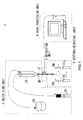
- Fig. 1 illustrates a flow cytometer according to an embodiment of the present invention.
- the flow cytometer 1 includes a water flow unit 2, a detection unit 3, a data processing unit 4 and a sorting/retrieval unit 5.
- the water flow unit 2 includes a sheath flow generation section 2A that gives a predetermined sheath pressure to produce a sheath flow, which is then supplied via a sheath tube to an interflow chamber 2X.
- the water flow unit 2 also includes a sample flow generation section 2B that gives a predetermined sample pressure to generate a sample flow, which is then supplied via a sample tube to the interflow chamber 2X.
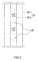
- the combined stream or layer flow LF spouts out from an outlet OP of a nozzle of the interflow chamber 2X, the sample flow being in the center of the combined stream while the sheath flow in the rim of the stream.
- the water flow unit 2 is designed to control the layer flow FL: The sample flow does not mix up with the sheath flow covering the sample flow and each sample flows separately in the sample flow.
- the layer flow FL is turbulent when R > 1000.
- the layer flow FL is stable when R ⁇ 1000.
- Such a state of the layer flow FL with R ⁇ 1000 is known as laminar flow. Since fluid viscosity largely depends on temperature, the sheath flow generation section 2A appropriately controls temperature for the sheath flow.
- the detection unit 3 is placed in the path of the layer flow. By using a quasi-electrostatic field, the detection unit 3 electrically detects a marker (label substance) attached to target samples, each of which separately exists in the sample flow. The detection unit 3 subsequently supplies resulting detection data to the data processing unit 4.
- a marker label substance
- the data processing unit 4 is a computer to identify the type of the target sample from the detection data. After identifying the type, the data processing unit 4 decides how much charge voltage it will apply to the target sample.
- the sorting/retrieval unit 5 applies the charge voltage, determined by the data processing unit 4, to the sample flow when the layer flow LF breaks into droplets (break off point).
- the flow cytometer 1 identifies and sorts out the target sample.
- the following describes the marker attached to the target samples.
- the marker is used to identify the sample.
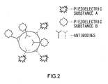
- the marker used in this embodiment is a piezoelectric substance of a unique vibration frequency, including a piezoelectric crystal, a piezoelectric ceramics, a piezoelectric thin film, a piezoelectric polymer substance and a ferrodielectric substance (also known as relaxor).
- the piezoelectric substance can be: crystal (SiO 2 ), lithium niobate (LiNbO 3 ), barium titanate (BaTiO 3 ), lead titanate (PbTiO 3 ), lead zirconate titanate (PZN), lead metaniobate (PbNb 2 O 6 ), polyvinylidene fluoride (PVDF) and zinc oxide (ZnO).
- the piezoelectric substance also can be: lithium tantalite (LiTaO 3 ), potassium niobate (K 4 NbO 3 ), lithium tetraborate (Li 2 B 4 O 7 ), langasite (La 3 Ga 5 SiO 14 ), aluminum nitride (AlN) and tourmaline.
- the method of attaching the marker (i.e. piezoelectric substance) to a target sample is: attaching the piezoelectric substance to a probe that is specific to a distinctive part of the target sample and then attaching the probe with the piezoelectric substance to the distinctive part of the target sample.
- the probe can be an antibody. This kind of probe is used to detect a certain cell because an antibody is attached to the corresponding antigen by the primary antibody method, the secondary antibody method or affinity of avidin/biotin.
- the probe may also include Annexin V, and MHC class I - peptide tetramer and the like. They are a high molecular weight protein of the immunoglobulin superfamily, used for detecting apoptotic cells or antigen-specific CD8 + T cells.
- probes such as DNA oligomer or RNA oligomer, which utilizes characteristic of complementary binding of DNA and RNA. Those probes are used to detect the sequences of DNA or RNA because they attach to a specific sequence by hybridization.
- the piezoelectric substance to the probes there are methods to attach the piezoelectric substance to the probes.
- One of the methods is directly attaching the piezoelectric substance to the probes.
- the other is attaching the piezoelectric substance to the probes through organic polymeric materials such as dextran, albumin, starch, polyacrylamide and polyethylene glycol (refer to: Inada Yuji, protein hybridization Vol. 3, Kyoritsu Shuppan Co., Ltd. 1990 ).
- each of them may be a piezoelectric substance of a different vibration frequency to be attached to the target cell.
- the piezoelectric substances (A and B), each of which has a different vibration frequency are attached to the antigens through corresponding antibodies or probes. In this manner, one or more unique piezoelectric substances are attached to the target sample.
- the target samples labeled by the markers, are put into solution (such as normal saline solution) along with gold fine particles.
- the solution is poured into the sample flow generation section 2B of the water flow unit 2. Accordingly, as shown in FIG. 3, the sample flow SF2, the center stream of the layer flow LF, includes the target cell and a plurality of gold fine particles GP around the cells.
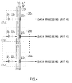
- the detection unit 3 includes a layer flow tube 10 and a plurality of marker detection sections 20 1 to 20 n .
- the layer flow tube 10 is connected to the interflow chamber 2X of the water flow unit 2.
- the layer flow tube 10 is placed as if the inner surface of the layer flow tube 10 covers the outer layer (i.e. the sheath flow SF1) of the layer flow LF emerging from the outlet OP of the nozzle of the interflow chamber 2X.
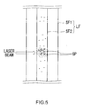
- the laser beams are emitted from the laser beam sources 21 1 to 21 n via the optical components 22 1 to 22 n toward the sample flow of the layer flow LF. If the wavelength of the laser beams is larger than the diameter of the gold fine particles GP (FIG. 3) in the sample flow, the laser beams collide with the gold fine particles GP, generating a quasi-electrostatic field (i.e. a near field) inside a certain area of the surface of the gold fine particles GP, as shown in FIG. 5.
- a quasi-electrostatic field i.e. a near field
- the laser beams are set at the same frequencies (f 1 to f n ) as the vibration frequencies of the piezoelectric substances (out of a plurality of piezoelectric substances of different vibration frequencies), which are associated with the target samples.
- the sample flow SF2 carries the target sample labeled by the piezoelectric substance of a certain vibration frequency.
- the target sample reaches an area to which the laser beam of the same frequency as the piezoelectric substance is emitted and then the target sample's piezoelectric substance gets into the quasi-electrostatic field (near field) around the gold fine particles GP, the piezoelectric substance begins to vibrate in a specific frequency (i.e. inverse piezoelectric effect).
- the elastic wave detection sections 23 1 to 23 n detect its vibration distortion as elastic waves.
- the elastic waves do not interfere with the charge voltage, which is applied to the sample flow SF2 by the sorting/retrieval unit 5, because the frequency of the elastic waves is different from that of the charge voltage.
- each of the elastic wave detection sections 23 1 to 23 n includes a piezoelectric plate 31 on which an Inter Digital Transducer (IDT) 32 is placed.
- the piezoelectric plate 31 will be in sympathetic vibration with the elastic waves from the target sample to generate a surface wave (i.e. piezoelectric effect).
- the IDT 32 includes two comb-shaped conductors facing each other as if being interlocked, serving as a filter to extract a certain signal component.
- the IDT 32 of the elastic wave detection sections uses a certain material for the piezoelectric plate with a certain interval regarding the teeth of the comb-like conductors such that they are suitable for the frequency of the laser beams emitted from the laser beam sources 21 1 to 21 n (FIG. 4). Accordingly, the IDT 32 of the elastic wave detection sections retrieves a wave of the same frequency as the corresponding piezoelectric substance from the surface waves generated around the piezoelectric plate 31 and then supplies a resulting detection signal S1 to the data processing unit 4 (FIG. 1).
- the detection unit 3 has the light sources at certain intervals, which emit the laser beams of different frequencies to the sample flow SF2 and the gold fine particles inside the flow SF2, generating a quasi-electrostatic field around the gold fine particles. Accordingly, the piezoelectric substance attached to the target sample will be in sympathetic vibration around the area to which the laser beams are emitted.
- the elastic wave detection sections 23 1 to 23n detects the vibration and then supplies the resulting detection signal S1 (FIG. 6) to the data processing unit 4 (FIG. 1).
- the data processing unit 4 includes a Central Processing Unit (CPU) 41 connected to a Read Only Memory (ROM) 42, which stores various programs, a Random Access Memory (RAM) 43, which serves as a work memory for the CPU, a signal input section 44 and a storage section 45.
- CPU Central Processing Unit
- ROM Read Only Memory
- RAM Random Access Memory
- the signal input section 44 amplifies the detection signal S1, supplied from the IDT 32 (FIG. 6) of the elastic wave detection sections 23 1 to 23 n , and then performs an Analog-to-Digital (A/D) conversion process.
- the signal input section 44 subsequently supplies resultant detection data D1 to the CPU 41.
- the storage section 45 stores a database (also referred to as a "sample identification table") in which the types of the target samples, the condition of the markers (or piezoelectric substances) for the target samples and the values of the charge voltages applied to the target samples are associated with one another.
- a database also referred to as a "sample identification table” in which the types of the target samples, the condition of the markers (or piezoelectric substances) for the target samples and the values of the charge voltages applied to the target samples are associated with one another.
- the CPU 41 executes a program stored in the ROM 42 and then identifies the type of the target sample in the sheath flow, based on the sample identification table and the detection data D1 from the signal input section 44. In addition, the CPU 41 determines how much charge voltage it will apply to the target sample.
- FIG. 9 is a flowchart illustrating the process of the CPU 41.
- the CPU 41 starts running the water flow unit 2, the detection unit 3 and the sorting/retrieval unit 5, and then proceeds to step SP1.
- the CPU 41 waits until it receives the detection signal S1 from the elastic wave detection sections 23 1 to 23 n .
- the CPU 41 After receiving the detection signal S1 from the elastic wave detection sections 23 1 to 23 n , the CPU 41 proceeds to step SP2. At step SP2, the CPU 41 identifies the type of the target sample that has passed through the elastic wave detection sections 23 1 to 23 n , based on the detection signal S1 and the sample identification table (FIG. 8) stored in the storage section 45. In addition, the CPU 41 determines how much charge voltage it will apply to the target sample.
- the CPU 41 at step SP 3 notifies the sorting/retrieval unit 5 of the charge voltage level determined at step SP2 and then returns to step SP1.
- the sorting/retrieval unit 5 will apply that level of the charge voltage to the sample flow when the droplets break off the flow (break off point).
- the charged droplet including the target sample is broken off from the flow by the deflection plate 5A or 5B, flowing into one of collection tubes CT 1 to CT m .
- the data processing unit 4 analyzes the target samples based on the detection result of the detection unit 3. In addition, the data processing unit 4 controls the sorting/retrieval unit 5 such that each collection tube CT collects a corresponding target sample.
- the flow cytometer 1 controls the laser beam source 21 to emit the laser beam to the layer flow LF in which there is gold fine particles GP whose radius is smaller than the wavelength of the electromagnetic wave.
- the sample flow SF2 part of the layer flow LF, carries the gold fine particles GP having the lowest ionization tendency and the target samples labeled by the piezoelectric substance of a unique vibration frequency (FIG. 3).
- the flow cytometer 1 applies the laser beam to the gold fine particles GP in the sample flow SF2 to create a quasi-electrostatic field on the surface of the gold fine particles GP (FIG. 5) and then detects vibration of the particles.
- the flow cytometer 1 produces a quasi-electrostatic field (i.e. a near field) on a specific area of the surface of the gold fine particle GP around the target sample. Accordingly, even if the markers (or piezoelectric substances) exist behind the direction of the emitted laser beam, the quasi-electrostatic field may cover the gold fine particles GP, allowing the flow cytometer 1 to detect the target sample.
- a quasi-electrostatic field i.e. a near field
- the quasi-electrostatic field is generated only on a specific area of the surface of the gold fine particles GP around the target sample. This may eliminate the effect of noise for precise detection.
- the flow cytometer 1 includes a plurality of laser beam sources 21 1 to 21 n and elastic wave detection section 23 1 to 23n to detect a plurality of piezoelectric substances of different vibration frequencies:
- One detection unit is a pair of a laser beam source 21 and an elastic wave detection section 23. Those detection units are spaced, along the layer flow, a predetermined distance away from each other so as to prevent the laser beams from the laser beam sources from affecting each other.
- each detection unit detects a piezoelectric substance of a different vibration frequency. This enables the flow cytometer 1 to precisely detect the markers attached to the target sample even if there are various piezoelectric substances of different vibration frequencies as the markers of the target sample.
- the flow cytometer 1 according to the present embodiment can be downsized, compared to a typical laser-type flow cytometer that includes complex optical components for sorting out various types of scattered beams into corresponding detectors in order to detect the target samples labeled by various fluorescent markers.
- the flow cytometer 1 has the layer flow tube 10 that carries the layer flow LF as if it covers the surface of the layer flow LF. Between the inner and outer surfaces of the layer flow tube 10 are placed the elastic wave detection sections 23 to make the elastic wave detection sections 23 close to the sample flow SF2. This allows the elastic wave detection sections 23 to precisely detect the vibration of the piezoelectric substances attached to the target samples. That also eliminates the effect of noise for precise detection.
- the flow cytometer 1 can precisely detect the markers because it generates the quasi-electrostatic fields on the gold fine particles around the target samples for the inverse piezoelectric effect and then detects the vibration of the markers attached to the target samples.
- the piezoelectric substances are used as markers.
- the markers may include electrostrictive materials of certain vibration frequencies.
- the electrostrictive materials represents: When an electric field is applied to the crystal, the resulting strain will be proportional to the square of the polarization.
- the electrostrictive materials may be useful because there is no need for polarizing process for the electrostrictive materials (while the piezoelectric substance may need the polarizing process) and they have a symmetrical appearance.
- the gold fine particles are used as a substance to be scattered around the target samples in the sample flow SF2.
- That substance may include the low ionization-tendency materials like gold (Au) to silver (Ag), among the particles of Pt, Pd, Ag and the like.
- gold or platinum particles may be useful in terms of the safety for human being (such as examiners or mine workers) and the stability of the materials.
- the detection unit 3 includes: the layer flow tube 10, which carries the layer flow FL from the nozzle such that its inner surface covers the outer layer flow or the sheath flow SF1; the laser beam sources 21 1 to 21 n ; the optical components 22 1 to 22 n for adjusting the direction of the laser beams so that they travel in a direction perpendicular to the sample flow SF2 of the layer flow LF; and the elastic wave detection sections 23 1 to 23 n .
- the present invention is not limited to this.
- the detection unit 3 may be configured in a different manner.
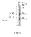
- FIG. 10 illustrates another configuration of the detection unit (the parts of FIG. 10 are represented as the same reference numerals and symbols as the corresponding parts of FIG. 4).
- the detection unit instead of the laser beam sources 21 1 to 21 n (each of which emits a certain frequency of laser beam), the detection unit (FIG. 10) includes one laser beam source 21x to emit the laser beams of various frequencies, such as differential Gaussian pulse.
- the target samples reach the area where they receive the laser beams from the laser beam source 21x.
- the piezoelectric substance attached to the target samples gets into the quasi-electrostatic fields (like FIG. 5) around the gold fine particles GP, the piezoelectric substance vibrates in its unique vibration frequency (i.e. inverse piezoelectric effect) and therefore the elastic wave detection sections 23 1 to 23 n detect the vibration distortion as elastic waves.
- each elastic wave detection section 23 1 to 23 n detects a corresponding vibration frequency of piezoelectric substance and then generate the detection signal S1 (FIG. 6).
- the detection unit (FIG. 10) allows the flow cytometer to be downsized because it has less number of laser beam sources to minimize the space for the layer flow tube 10.
- the elastic wave detection sections 23 1 to 23 n may need to be placed in the quasi-electrostatic fields generated around the gold fine particles GP.
- the detection unit may use, as the waves of various frequencies, surface transverse waves (STW), Rayleigh waves (SAW), SH surface waves (BGS wave: Bleustein-Gulyaev-Simizu wave), Lamb waves, Surface-Skimming waves, Shear Horizontal (SH) bulk waves and the like.
- STW surface transverse waves
- SAW Rayleigh waves
- SH SH surface waves
- Lamb waves Surface-Skimming waves
- SH Shear Horizontal
- the elastic wave detection sections 23 are used as detection means for detecting vibration of particles (such as piezoelectric or electrostrictive substances).
- the detection section may include a piezoelectric plate and a band pass filter connected to the plate, as a Surface Acoustic Wave (SAW) device to detect a specific elastic wave or the vibration of the particle.
- SAW Surface Acoustic Wave
- the flow cytometer 1 applies electric charge (for a certain type of sample) to the sample flow SF2 and then the charged droplet including the target sample are broken off from the flow by the deflection plates 5A and 5B with predetermined positive and negative voltages at the break off point.
- the present invention is not limited to this.
- a predetermined charge voltage may be applied to the sample flow SF2 while the voltage applied to the deflection plates 5A and 5B changes according to the type of the target sample to attract the droplets including different samples in different ways.
- the method according to an embodiment of the present invention can be applied to medicine production.
Landscapes
- Physics & Mathematics (AREA)
- Biochemistry (AREA)
- General Physics & Mathematics (AREA)
- Life Sciences & Earth Sciences (AREA)
- Chemical & Material Sciences (AREA)
- Analytical Chemistry (AREA)
- Acoustics & Sound (AREA)
- General Health & Medical Sciences (AREA)
- Health & Medical Sciences (AREA)
- Immunology (AREA)
- Pathology (AREA)
- Investigating Or Analysing Biological Materials (AREA)
- Investigating Or Analysing Materials By Optical Means (AREA)
- Investigating Or Analyzing Materials By The Use Of Ultrasonic Waves (AREA)
- Investigating Or Analyzing Materials By The Use Of Electric Means (AREA)
Applications Claiming Priority (1)
| Application Number | Priority Date | Filing Date | Title |
|---|---|---|---|
| JP2006287899A JP4304634B2 (ja) | 2006-10-23 | 2006-10-23 | 標識検出装置及び標識検出方法 |
Publications (3)
| Publication Number | Publication Date |
|---|---|
| EP1916519A2 true EP1916519A2 (de) | 2008-04-30 |
| EP1916519A3 EP1916519A3 (de) | 2010-01-13 |
| EP1916519B1 EP1916519B1 (de) | 2011-04-20 |
Family
ID=39015771
Family Applications (1)
| Application Number | Title | Priority Date | Filing Date |
|---|---|---|---|
| EP07254186A Not-in-force EP1916519B1 (de) | 2006-10-23 | 2007-10-22 | Vorrichtung und Verfahren zur Markerdetektion |
Country Status (4)
| Country | Link |
|---|---|
| US (1) | US7797999B2 (de) |
| EP (1) | EP1916519B1 (de) |
| JP (1) | JP4304634B2 (de) |
| DE (1) | DE602007013988D1 (de) |
Cited By (5)
| Publication number | Priority date | Publication date | Assignee | Title |
|---|---|---|---|---|
| US10605714B2 (en) | 2015-10-19 | 2020-03-31 | Sony Corporation | Image processing device, fine particle sorting device, and image processing method |
| US10876952B2 (en) | 2014-09-05 | 2020-12-29 | Sony Corporation | Droplet sorting device, droplet sorting method and program |
| US11119030B2 (en) | 2014-02-13 | 2021-09-14 | Sony Corporation | Particle sorting device, particle sorting method, program, and particle sorting system |
| US11193874B2 (en) | 2012-03-30 | 2021-12-07 | Sony Corporation | Micro-particle sorting apparatus and method of determining a trajectory of an ejected stream carrying micro-particles |
| US11313784B2 (en) | 2013-01-28 | 2022-04-26 | Sony Corporation | Microparticle sorting device, and method and program for sorting microparticles |
Families Citing this family (5)
| Publication number | Priority date | Publication date | Assignee | Title |
|---|---|---|---|---|
| JP4304633B2 (ja) * | 2006-10-23 | 2009-07-29 | ソニー株式会社 | 標識検出装置及び標識検出方法 |
| CN103718020B (zh) | 2012-03-30 | 2016-06-29 | 索尼公司 | 微粒分类装置及在该装置中优化流体流的方法 |
| US10309891B2 (en) | 2013-10-16 | 2019-06-04 | Sony Corporation | Particle sorting apparatus, particle sorting method, and program |
| JP6136843B2 (ja) | 2013-10-17 | 2017-05-31 | ソニー株式会社 | 粒子分取装置、粒子分取方法及びプログラム |
| US9897531B2 (en) * | 2014-06-03 | 2018-02-20 | Intellicyt | Flow cytometry sample separation methods and apparatus |
Citations (2)
| Publication number | Priority date | Publication date | Assignee | Title |
|---|---|---|---|---|
| JPH09508703A (ja) | 1994-08-01 | 1997-09-02 | アボツト・ラボラトリーズ | フローサイトメトリック血液細胞分析器用の擬似テレセントリック光学設計 |
| JP2006287899A (ja) | 2005-03-09 | 2006-10-19 | Toyota Central Res & Dev Lab Inc | ダイバーシチ受信装置 |
Family Cites Families (5)
| Publication number | Priority date | Publication date | Assignee | Title |
|---|---|---|---|---|
| US5641457A (en) * | 1995-04-25 | 1997-06-24 | Systemix | Sterile flow cytometer and sorter with mechanical isolation between flow chamber and sterile enclosure |
| WO2003008937A2 (en) * | 2001-07-18 | 2003-01-30 | The Regents Of The University Of Michigan | Gas-focusing flow cytometer cell and flow cytometer detection system with waveguide optics |
| US20040260157A1 (en) * | 2003-06-20 | 2004-12-23 | Montes Miguel A. | Method for automated screening of cervical/endocervical malignant and premalignant epithelial lesions using flow cytometry with HPV DNA fluorescent in-situ hybridization ( FISH) technology |
| US7340957B2 (en) * | 2004-07-29 | 2008-03-11 | Los Alamos National Security, Llc | Ultrasonic analyte concentration and application in flow cytometry |
| US7727775B2 (en) * | 2004-10-25 | 2010-06-01 | Willson Richard C | Optical microlabels: shapes and reflectors |
-
2006
- 2006-10-23 JP JP2006287899A patent/JP4304634B2/ja not_active Expired - Fee Related
-
2007
- 2007-10-19 US US11/875,411 patent/US7797999B2/en not_active Expired - Fee Related
- 2007-10-22 DE DE602007013988T patent/DE602007013988D1/de active Active
- 2007-10-22 EP EP07254186A patent/EP1916519B1/de not_active Not-in-force
Patent Citations (2)
| Publication number | Priority date | Publication date | Assignee | Title |
|---|---|---|---|---|
| JPH09508703A (ja) | 1994-08-01 | 1997-09-02 | アボツト・ラボラトリーズ | フローサイトメトリック血液細胞分析器用の擬似テレセントリック光学設計 |
| JP2006287899A (ja) | 2005-03-09 | 2006-10-19 | Toyota Central Res & Dev Lab Inc | ダイバーシチ受信装置 |
Non-Patent Citations (1)
| Title |
|---|
| INADA YUJI: "protein hybridization", vol. 3, 1990, KYORITSU SHUPPAN CO., LTD. |
Cited By (6)
| Publication number | Priority date | Publication date | Assignee | Title |
|---|---|---|---|---|
| US11193874B2 (en) | 2012-03-30 | 2021-12-07 | Sony Corporation | Micro-particle sorting apparatus and method of determining a trajectory of an ejected stream carrying micro-particles |
| US11313784B2 (en) | 2013-01-28 | 2022-04-26 | Sony Corporation | Microparticle sorting device, and method and program for sorting microparticles |
| US11119030B2 (en) | 2014-02-13 | 2021-09-14 | Sony Corporation | Particle sorting device, particle sorting method, program, and particle sorting system |
| US10876952B2 (en) | 2014-09-05 | 2020-12-29 | Sony Corporation | Droplet sorting device, droplet sorting method and program |
| US10605714B2 (en) | 2015-10-19 | 2020-03-31 | Sony Corporation | Image processing device, fine particle sorting device, and image processing method |
| US11204309B2 (en) | 2015-10-19 | 2021-12-21 | Sony Corporation | Image processing device, fine particle sorting device, and image processing method |
Also Published As
| Publication number | Publication date |
|---|---|
| EP1916519A3 (de) | 2010-01-13 |
| US20080092655A1 (en) | 2008-04-24 |
| JP2008107110A (ja) | 2008-05-08 |
| DE602007013988D1 (de) | 2011-06-01 |
| US7797999B2 (en) | 2010-09-21 |
| JP4304634B2 (ja) | 2009-07-29 |
| EP1916519B1 (de) | 2011-04-20 |
Similar Documents
| Publication | Publication Date | Title |
|---|---|---|
| EP1916519B1 (de) | Vorrichtung und Verfahren zur Markerdetektion | |
| US8998483B2 (en) | Concentration and dispersion of small particles in small fluid volumes using acoustic energy | |
| US8263407B2 (en) | Method for non-contact particle manipulation and control of particle spacing along an axis | |
| US5629485A (en) | Contaminant detection sytem | |
| Pohanka | The piezoelectric biosensors: Principles and applications, a review | |
| US8387803B2 (en) | Particle sorting | |
| AU684706B2 (en) | A device for determining the size and charge of colloidal particles | |
| US8028582B2 (en) | Marker detection apparatus and marker detection method | |
| EP1841537A2 (de) | Verfahren und vorrichtung zur hydraulischen sortierung von teilchen | |
| US20050227362A1 (en) | Multiple sorter monitor and control subsystem for flow cytometer | |
| CN111054454A (zh) | 用于颗粒操控的微流控芯片 | |
| US6925856B1 (en) | Non-contact techniques for measuring viscosity and surface tension information of a liquid | |
| AU2026200844A1 (en) | Multiplexing Surface Acoustic Wave Sensors with Delay Line Coding | |
| US7281413B2 (en) | Acoustic method for determining the viscosity and/or surface tension of a liquid | |
| US12025549B2 (en) | Cell analyzers | |
| CN220467985U (zh) | 基于声波分离细胞及组织碎片的系统 | |
| CN216309741U (zh) | 基于移动聚焦表面声束的荧光激活细胞分选系统 | |
| EP1673622B1 (de) | Massenspektrometer für mitgeführte teilchen sowie verfahren zur messung der teilchenmassen | |
| JP4469974B2 (ja) | 微量液体分取装置及び微量液体分取方法 | |
| CN113316717A (zh) | 用于通过声波分析流体的传感装置 | |
| KR20080067027A (ko) | 유체에 부유하는 동일 크기 입자의 질량별 분리 장치 |
Legal Events
| Date | Code | Title | Description |
|---|---|---|---|
| PUAI | Public reference made under article 153(3) epc to a published international application that has entered the european phase |
Free format text: ORIGINAL CODE: 0009012 |
|
| 17P | Request for examination filed |
Effective date: 20071102 |
|
| AK | Designated contracting states |
Kind code of ref document: A2 Designated state(s): AT BE BG CH CY CZ DE DK EE ES FI FR GB GR HU IE IS IT LI LT LU LV MC MT NL PL PT RO SE SI SK TR |
|
| AX | Request for extension of the european patent |
Extension state: AL BA HR MK RS |
|
| PUAL | Search report despatched |
Free format text: ORIGINAL CODE: 0009013 |
|
| AK | Designated contracting states |
Kind code of ref document: A3 Designated state(s): AT BE BG CH CY CZ DE DK EE ES FI FR GB GR HU IE IS IT LI LT LU LV MC MT NL PL PT RO SE SI SK TR |
|
| AX | Request for extension of the european patent |
Extension state: AL BA HR MK RS |
|
| 17Q | First examination report despatched |
Effective date: 20100129 |
|
| AKX | Designation fees paid |
Designated state(s): DE FR GB |
|
| GRAP | Despatch of communication of intention to grant a patent |
Free format text: ORIGINAL CODE: EPIDOSNIGR1 |
|
| RIC1 | Information provided on ipc code assigned before grant |
Ipc: G01N 33/543 20060101ALI20101007BHEP Ipc: G01N 27/00 20060101AFI20101007BHEP |
|
| GRAS | Grant fee paid |
Free format text: ORIGINAL CODE: EPIDOSNIGR3 |
|
| GRAA | (expected) grant |
Free format text: ORIGINAL CODE: 0009210 |
|
| AK | Designated contracting states |
Kind code of ref document: B1 Designated state(s): DE FR GB |
|
| REG | Reference to a national code |
Ref country code: GB Ref legal event code: FG4D |
|
| REF | Corresponds to: |
Ref document number: 602007013988 Country of ref document: DE Date of ref document: 20110601 Kind code of ref document: P |
|
| REG | Reference to a national code |
Ref country code: DE Ref legal event code: R096 Ref document number: 602007013988 Country of ref document: DE Effective date: 20110601 |
|
| PLBE | No opposition filed within time limit |
Free format text: ORIGINAL CODE: 0009261 |
|
| STAA | Information on the status of an ep patent application or granted ep patent |
Free format text: STATUS: NO OPPOSITION FILED WITHIN TIME LIMIT |
|
| 26N | No opposition filed |
Effective date: 20120123 |
|
| REG | Reference to a national code |
Ref country code: DE Ref legal event code: R097 Ref document number: 602007013988 Country of ref document: DE Effective date: 20120123 |
|
| REG | Reference to a national code |
Ref country code: GB Ref legal event code: 746 Effective date: 20120703 |
|
| REG | Reference to a national code |
Ref country code: DE Ref legal event code: R084 Ref document number: 602007013988 Country of ref document: DE Effective date: 20120614 |
|
| PGFP | Annual fee paid to national office [announced via postgrant information from national office to epo] |
Ref country code: FR Payment date: 20121031 Year of fee payment: 6 |
|
| PGFP | Annual fee paid to national office [announced via postgrant information from national office to epo] |
Ref country code: GB Payment date: 20121019 Year of fee payment: 6 |
|
| GBPC | Gb: european patent ceased through non-payment of renewal fee |
Effective date: 20131022 |
|
| PG25 | Lapsed in a contracting state [announced via postgrant information from national office to epo] |
Ref country code: GB Free format text: LAPSE BECAUSE OF NON-PAYMENT OF DUE FEES Effective date: 20131022 |
|
| REG | Reference to a national code |
Ref country code: FR Ref legal event code: ST Effective date: 20140630 |
|
| PG25 | Lapsed in a contracting state [announced via postgrant information from national office to epo] |
Ref country code: FR Free format text: LAPSE BECAUSE OF NON-PAYMENT OF DUE FEES Effective date: 20131031 |
|
| PGFP | Annual fee paid to national office [announced via postgrant information from national office to epo] |
Ref country code: DE Payment date: 20161020 Year of fee payment: 10 |
|
| REG | Reference to a national code |
Ref country code: DE Ref legal event code: R119 Ref document number: 602007013988 Country of ref document: DE |
|
| PG25 | Lapsed in a contracting state [announced via postgrant information from national office to epo] |
Ref country code: DE Free format text: LAPSE BECAUSE OF NON-PAYMENT OF DUE FEES Effective date: 20180501 |