EP1916581A2 - Sicherheits-Gegenprobendiagnose in einem Sicherheitssystem mit zwei Zentralprozessoren - Google Patents
Sicherheits-Gegenprobendiagnose in einem Sicherheitssystem mit zwei Zentralprozessoren Download PDFInfo
- Publication number
- EP1916581A2 EP1916581A2 EP07119266A EP07119266A EP1916581A2 EP 1916581 A2 EP1916581 A2 EP 1916581A2 EP 07119266 A EP07119266 A EP 07119266A EP 07119266 A EP07119266 A EP 07119266A EP 1916581 A2 EP1916581 A2 EP 1916581A2
- Authority
- EP
- European Patent Office
- Prior art keywords
- processor
- safety
- cpu
- clock source
- processing unit
- Prior art date
- Legal status (The legal status is an assumption and is not a legal conclusion. Google has not performed a legal analysis and makes no representation as to the accuracy of the status listed.)
- Granted
Links
Images


Classifications
-
- G—PHYSICS
- G05—CONTROLLING; REGULATING
- G05B—CONTROL OR REGULATING SYSTEMS IN GENERAL; FUNCTIONAL ELEMENTS OF SUCH SYSTEMS; MONITORING OR TESTING ARRANGEMENTS FOR SUCH SYSTEMS OR ELEMENTS
- G05B19/00—Program-control systems
- G05B19/02—Program-control systems electric
- G05B19/04—Program control other than numerical control, i.e. in sequence controllers or logic controllers
- G05B19/042—Program control other than numerical control, i.e. in sequence controllers or logic controllers using digital processors
- G05B19/0428—Safety, monitoring
-
- G—PHYSICS
- G05—CONTROLLING; REGULATING
- G05B—CONTROL OR REGULATING SYSTEMS IN GENERAL; FUNCTIONAL ELEMENTS OF SUCH SYSTEMS; MONITORING OR TESTING ARRANGEMENTS FOR SUCH SYSTEMS OR ELEMENTS
- G05B2219/00—Program-control systems
- G05B2219/20—Pc systems
- G05B2219/25—Pc structure of the system
- G05B2219/25047—Common clock for redundant processors
Definitions
- the present invention relates to industrial "safety controllers" used for real-time control of industrial processes and appropriate for use in devices and systems intended to protect human life and health, and in particular to "safety I/O modules," a component of a safety system.
- Safety controllers are special purpose computers used to ensure the safety of humans working in the environment of an industrial process. Under the direction of a stored safety control program, a safety controller examines a series of inputs reflecting the status of the controlled process and changes a series of outputs controlling the industrial process.
- the inputs and outputs may be binary, i.e., on or off, or analog, i.e., providing a value within a continuous range.
- the inputs may be obtained from light curtains or other sensors attached to industrial process equipment and the outputs may be signals to power control relays, actuators or motors on the equipment.
- Safety I/O modules are a form of distributed inputs and outputs (“I/O") and are connected to and monitored by safety controllers.
- One benefit of using remote I/O include the ability to place I/O where the devices reside. This greatly improves the ability to maintain and troubleshoot the I/O and devices. Further, installation time and wiring costs are greatly reduced.
- Safety I/O modules in particular provide additional benefits such as the ability to monitor the I/O safety reaction time, discussed in greater detail below also known as the CIP (Common Industrial Protocol) safety protocol extensions. If a safety I/O module is processing an input or output, it provides a safety reaction time which must meet industry requirements.
- Safety systems are systems that incorporate safety controllers along with the electronics associated with emergency-stop buttons, interlock switches, light curtains and other machine lockouts to provide a safer working environment.
- the safety reaction time also known as the “safety response time” is defined as the amount of time from a safety-related event as input to the safety system until the system is in the safe state. In other words, it is the time from electrical recognition of a safety demand such as an e-stop button depressed or light curtain traversed, until all the system's actuators operation to a safe state.
- the safe state is different for each system and can range from a stopped motor, a closed valve or a deenergized electrical component.
- the safety reaction time of a safety system directly affects how close a component, e.g., a light curtain, can be placed to a piece of machinery, e.g., a press.
- a component e.g., a light curtain
- the time it takes for an operator's hand to pass through a light curtain and come into contact with an unsafe machine component is greater than the time required for the safety controller to receive the light curtain input signal, process it and direct the machinery into a safe mode. Therefore, the faster the safety reaction time, the closer light curtains and similar safety devices can be mounted to the machinery. This is particularly beneficial when installation space is limited or if the machine operation includes frequent operator interventions such as inserting and removing workpieces.
- the safety reaction time of an industrial system depends on the rate of data transmission between the components as well as the processing time of the safety controller.
- the safety reaction time is the sum of: the sensor reaction time, input reaction time, safety task reaction time, output reaction time and actuator reaction time. Each of these times is variably dependent on factors such as the type of I/O module and logic instructions within a specific safety program.
- the safety task reaction time of a controller is the worst-case delay from any input change presented to the controller until the processed output is set by the output producer.
- Each safety device implements a safety watchdog timer to limit the safety task reaction time to a maximum permissible time. If the safety task reaction time exceeds the safety watchdog timer, the safety device will fault and the outputs will automatically transition to a safe state.
- IEC International Electrotechnical Commission
- 615008 entitled Functional Safety of Electrical / Electronic / Programmable Electronic Safety-Related Systems.
- IEC 61508 specifies 4 safety integrity levels (SILs) of safety performance for a safety function.
- Safety systems with a SIL of 2 (SIL 2) and 3 (SIL 3) generally require redundancy for sensors, final control elements and control system processors.
- SIL 3-compliant safety devices typically have dual central processing units, also known as processors or CPUs, running independent safety functions.
- the safety functions have some shared commonality but also perform different tasks.
- the CPUs rely on standard watchdog timers, as are well known in the art, to verify that their clock sources are delivering a consistently steady clock pulse. Verification of the clock sources is needed to verify that the safety devices are providing the correct safety reaction times.
- watchdog timers are based on the frequency driving the CPU and therefore are only as accurate as the underlying clock source.
- a quartz-based oscillator is used to generate the clock pulses, i.e., the frequency, that drive a CPU, among other things. Under normal operating conditions, these oscillators are extremely reliable and durable. However, in an industrial environment, the crystals can get hot, jostled or contaminated causing them to drift and become unreliable.
- an oscillator clock source were to drift slower than the rated speed, the CPU driven by it would also run slower. For example, if a normally-rated 3.0 GHz CPU had a slightly slower clock source, it might instead run at 2.99999 GHz. If the system clock is tracking time by counting clock pulses, after 3.0 x 10 9 pulses, the actual elapsed time would be slightly longer than one second but the system clock would indicate that exactly one second has elapsed. Without an independent clock source to verify that 3.0 x 10 9 pulses took exactly one second, the CPU would have no way to know that it was operating slower or faster than normal.
- each CPU in a dual-CPU safety device have an independent clock source to verify that its own single clock source is operating within specified parameters.
- Traditional safety devices have multiple independent clock sources and therefore can use one of those clock sources when running a diagnostic to verify the accuracy of the primary clock source.
- each CPU may have only one clock source.
- one possible solution to the lack of independently verifying clock sources would be to use the clock source of the partner CPU to cross-check and verify the accuracy of the clock source of the primary CPU.
- this solution provides no way to ensure that the clock source of the partner, i.e., verifying, CPU is accurate. If the verifying CPU's clock source has drifted, it will not provide proper verification of the accuracy of the primary CPU's clock source. In other words, in the absence of a cross check, an inaccurate clock source in the partner CPU could be used to check the clock source of the primary CPU as well as verify that its own safety critical functions were completed within the rated safety reaction time
- the present invention provides a dual-CPU safety device that validates the accuracy of the clock source for each CPU. Through a diagnostic, the first CPU verifies the accuracy of the clock source of a second CPU and then the second CPU verifies the clock source of the first CPU, If it is determined that either CPU has a faulty clock source, the safety device faults and the controlled process enters a safe state.
- a safety device comprises a first processing unit having a first processor, i.e., CPU, driven by a first clock source executing a first safety loop of safety critical functions, or routines, a second, independent processing unit having a second processor driven by a second clock source executing a second safety loop of safety critical functions, a communication link between the first and second processors, a synchronization routine and a diagnostic.
- the synchronization routine is executed by the first and second processors to synchronize the start of a cycle of their respective safety loops.
- the diagnostic is executed by both the first and second processors such that one processor verifies the completion of its own safety tasks while the other processor monitors the accuracy of the clock source of the first processor.
- the first processor verifies that it has completed all the safety critical functions of a safety loop within the safety reaction time while the second processor verifies the clock source of the first processor.
- the first processor checks whether all of its safety critical functions have been completed. If not, the first processor faults. If they have been completed, the first processor sends a rendezvous signal to the second processor which then determines if the safety reaction time, as determined by the first processor using its clock source, is within a pre-set range. This check verifies whether or not the clock source of the first processor is reliably providing clock pulses. If it is not, the second processor faults and enters a safe state. If the second processor does not receive the rendezvous signal before it times out, it will also fault.
- the first and second processors swap roles wherein the first processor monitors the accuracy of the clock source of the second processor.
- the second processor verifies its safety critical functions have been completed. If not, the second processor faults. If they have been completed, the second processor sends a rendezvous signal to the first processor which then determines if the safety reaction time, as determined by the second processor using its clock source, is within a pre-set range. The two processors continue swapping roles while the diagnostic is running.
- FIG. 1 is an industrial control system that includes a dual-CPU safety device suitable for use with the present invention having a controlling and validating CPU;
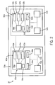
- FIG. 2 is an electrical schematic representation of a controlling and validating processor in the safety device of FIG. 1;
- FIG. 3 is a flowchart of a safety timer cross-check diagnostic executed in the dual CPU safety device of FIG. 1,
- the industrial control system 10 utilizes programmable input/output (I/O) circuits that are described in greater detail below. It should be noted that the industrial control system 10 is merely one example of an industrial control system that could utilize the present invention, and that other systems are also possible.
- I/O input/output
- the industrial control system 10 comprises a programmable control system 12 that controls the output status of a plurality of output devices 14 based on the input status of a plurality of input devices 16.
- the programmable control system 12 has a microprocessor-based processor module 17 that executes a stored control program which defines the manner in which the output devices 14 are controlled.
- the processor module 17 communicates with the I/O devices 14 and 16 by way of an I/O module 18.
- the processor module 17 transmits a digital representation of the desired output status of the output devices 14 to the I/O module 18.
- the I/O module 18 Based on the digital representation of the desired output status of the output devices 14, the I/O module 18 produces an output control signal that is capable of driving the output devices 14 in the desired manner.
- the processor module 17 receives a digital representation of the input status of the input devices 16 from the I/O module 18.
- the I/O module 18 produces the digital representation of the input status of the input devices 16 based on input status signals received from the input devices 16.
- a controlled safety process 40 includes a light curtain 42 providing redundant light curtain signals 44 to the I/O module 18 and a press 46 that may be stopped via a halt signal 48 sent to the press 46 from the I/O module 18.
- the safety process 40 is designed to stop the press 46 if the plane of the light curtain 42 is crossed.
- the speed of response, i.e., the safety reaction time, of the I/O module 18 in halting the press 46 after an object cross the plane of the light curtain 42 is factored into the calculation to determine the required amount of separation between the light curtain 42 and the press 46.
- I/O module 18 includes primary processing unit 50a communicating via a serial communication protocol known in the art to partner processing unit 50b.
- Primary processing unit 50a includes a first, or controlling processor, or CPU, 52a and a system clock 53a, both of which are driven by a single clock source 54a.
- the system clock 53a in a preferred embodiment increments in one microsecond intervals.
- the CPU 52a has an internal ROM 56a (read only memory) which holds an executive, or firmware, image 58a of executables 60a comprised of safety critical functions 61a, diagnostic code 62a, and non-safety functions 63a, CPU 52a further includes a flag 64a and a timer interrupt function implemented with a compare register 66a wherein the compare register 66a is loaded with a preset time value. When the system clock 53a reaches the value stored in the compare register 66a, CPU 52a will interrupt the execution of the executive image 58a.
- Partner processing unit 50b includes mostly the same, though independent, components including a processor 52b and system clock 53b driven by a single clock source 54b, ROM 56b, firmware image 58b of slightly different executables 60b comprised of safety critical functions 61b, diagnostic code 62b and non-safety functions 63b, flag 64b and compare register 66b providing the same timer interrupt functionality.
- FIG. 3 is a visual representation of the process wherein I/O Module 18 performs the safety timer cross-check diagnostic 100 beginning at start blocks 104, 108 representing a "safety loop" initialization process.
- the safety loop initialization process serves two functions; it ensures that both CPUs 52a, 52b have interrupts loaded prior to entry of the safety loop and it also synchs up the two CPUs 52a, 52b to begin the safety loop at the same time. This synching is shown by a rendezvous message 106 and an acknowledgement message 110 between the two processing units 50a, 50b.
- timer compare registers 66a, 66b are used to generate the interrupts in CPUs 52a, 52b.
- the first interrupt is scheduled in CPU 52a, acting as controlling CPU, by loading compare register 66a with a value representing the 6ms from when the previous interrupt was scheduled to occur.
- the 6 ms time period represents the rated safety reaction time of the I/O module 18.
- An interrupt is also scheduled in CPU 52b, acting as monitoring CPU, to occur at a time slightly longer than the 6ms time loaded into CPU 52a.
- the extra time acts as a cushion or tolerance and is necessary due to the slight delay between CPU 52a being interrupted and processing unit 50a sending a rendezvous message to processing unit 50b as well as to allow for slight time differences between the processing units 50a, 50b.
- processing units 50a, 50b After the interrupts have been scheduled, i.e., after the timer compare registers 66a, 66b have been loaded, processing units 50a, 50b have essentially begun executing a first safety loop 127.
- processing unit 50a acts as the controlling unit while partner processing unit 50b acts as the monitoring unit.
- CPUs 52a, 52b in each processing unit 50a, 50b process the executables 60a, 60b, including safety critical functions 61a, 61 b and non-safety functions 63a, 63b.
- an internal flag 64a is set.
- This flag indicates that the safety critical functions 61a, have been completed by the controlling CPU 52a within the rated safety reaction time. Thereafter, CPU 52a executes non-safety functions 63a while waiting for the timer interrupt, shown as block 116. Meanwhile, CPU 52b finishes executing safety critical functions 61b, sets flag 64b and begins executing non-safety functions 63b while waiting for either rendezvous message 120 from processing unit 50a or for its own timer interrupt, shown as block 122.
- CPU 52a interrupts the processing of the executive image 58a.
- CPU 52a could repeatedly poll a timer or counter to determine when the time has elapsed.
- this is not the preferred approach as it offers no watchdog function to protect against the case where CPU 52a encounters unexpected delays.
- CPU 52a After the interrupt occurs, CPU 52a immediately schedules a new interrupt to occur after another 6ms plus the cushion have elapsed.
- the cushion is included because CPU 52a becomes the monitoring unit during the next safety loop 128.
- the interrupt is scheduled by loading the compare register 66a with a value representing the next desired interrupt time and is scheduled immediately after the previous interrupt to ensure that processing system 50a is always protected against any unexpected delays.
- CPU 52a next checks whether or not flag 64a is set. If flag 64a is not set, i.e., all the safety critical functions 61a were not completed, a hard or critical fault occurs. Processing unit 50a goes into a safe state and then resets. If the flag 64a is set, a rendezvous signal 120 is sent to processing unit 50b from block 118 to indicate that the time value loaded into compare register 66a, i.e., the safety reaction time of 6 ms, has elapsed as perceived by processing unit 50a.
- processing unit 50b receives the rendezvous signal 120 and promptly replies with an acknowledgement signal 124. In the event of an unexpected delay or inaccurate clock such that CPU 52b is interrupted before receiving rendezvous signal 120, a critical fault will occur wherein the processing unit 50b will go into a safe state and then reset. Otherwise, after receiving rendezvous message 120, CPU 52b checks whether or not flag 64b is set, indicating that all safety functions 61b have been completed. If flag 64b is not set, a critical fault will also occur. If flag 64b is set, processing unit 50b determines whether or not the elapsed safety reaction time, as determined by CPU 52a using clock source 54a, is within the allowable range or cushion (decision block 130). In essence, processing unit 50b is checking the accuracy of clock source 54a by comparing what processing unit 50a determined 6 ms to be against what processing unit 50b, using clock source 54b, determined 6 ms (plus the cushion) to be.
- processing unit 50b If the safety reaction time of processing unit 50a is not within an acceptable range, the processing unit 50b will fault, shown as block 132. If the safety reaction time of processing unit 50a is within the acceptable range, processing unit 50b moves to block 134 and schedules the next interrupt. Since CPU 52b will act as the controlling CPU in the next safety loop 128, the value loaded into timer compare register 66b is the value of 6 ms from the current time.
- the roles of the primary processing unit 50a and partner processing unit 50b are reversed wherein the primary processing unit 50a becomes the monitoring processing unit while partner processing unit 50b becomes the controlling processing unit.
- This symmetry i.e., role-swapping, is useful because at this point in the diagnostic 100, only the clock source 54a of primary processing unit 50a has been verified as being accurate.
- the diagnostic 100 ensures that both CPUs 52a, 52b have the ability to accurately measure time as well as the ability to interrupt to generate a fault.
- CPUs 52a, 52b of each processing unit 50a, 50b process the executables 60a, 60b, including safety critical functions 61a, 61b again. After completing the safety functions 61 a, 61 b, internal flags 64a, 64b are set. Thereafter, CPU 52b waits for its timer interrupt shown as block 138 while CPU 52a waits for either rendezvous message 142 from processing unit 50b or for its own timer interrupt.
- CPU 52b interrupts processing. After the interrupt, the CPU 52b immediately schedules a new interrupt (with cushion) to prepare for monitoring, as previously discussed. Next, CPU 52b checks whether or not the flag 64b is set. If flag 64b is not set, a critical fault occurs in processing unit 50b which goes to a safe state and then resets.
- a rendezvous signal 142 is sent to processing unit 50a to indicate that the time loaded into compare register 66b, i.e., the safety reaction time of 6 ms, has elapsed as determined by processing unit 50b using clock source 54b.
- Processing unit 50a meanwhile receives signal 142 (block 144) and promptly replies with acknowledgement signal 146.
- Processing unit 50b enters a new safety loop and begins processing safety functions 61a (shown as return path 148 to safety loop 127).
- CPU 52a In the event that CPU 52a is interrupted before receiving rendezvous signal 142, (as a result of an unexpected delay or inaccurate clock), a critical fault occurs wherein the processing unit 50a will go to a safe state and then reset. After receiving rendezvous signal 142, CPU 52a checks whether or not flag 64a is set. If flag 64a is not set, a critical fault would also occur. If flag 64a is set, processing unit 50a (decision block 150) determines whether or not the elapsed safety reaction time, as calculated by CPU 52b using clock source 54b, is within the allowable range or cushion.
- processing unit 50a If the safety reaction time, as determined using clock source 54a, is not within the acceptable range, the processing unit 50a will fault, shown as block 152. If the safety reaction time is within the acceptable range, processing 50a unit moves to block 154 where the next interrupt is scheduled. Since 52a will be the controlling CPU again, the value loaded into timer compare register 66a would be 6 ms from the time the last interrupt was scheduled by CPU 52a, in block 116 (ensuring that the combined time of safety loops 127 and 128 is exactly two safety reaction times, i,e., 12 ms). Processing unit 50a then enters a new safety loop and begins processing safety functions 61 a (shown as return path 156 to safety loop 127).
- the safety timer cross-check diagnostic 100 can be repeated at a pre-determined frequency while CPUs 52a, 52b of processing units 50a, 50b continue to perform the executables 60a, 60b, within the safety loops. It is specifically intended that the present invention not be limited to the embodiments and illustrations contained herein, but include modified forms of those embodiments including portions of the embodiments and combinations of elements of different embodiments as come within the scope of the following claims.
- the invention discloses a dual-processing unit with single clock source CPUs safety I/O module having a safety timer crosscheck diagnostic to enable each CPU to verify the accuracy of the clock source of the other CPU.
- the diagnostic works by having the first CPU act as a controlling CPU and the second CPU act as a monitoring CPU.
- Both CPUs are synchronized to begin one cycle of their respective safety functions at the same time.
- the controlling CPU is set to be interrupted after a pre-determined time period while the monitoring CPU is set to be interrupted slightly after that.
- the controlling CPU When the controlling CPU is interrupted after the pre-determined time has passed as determined by that CPU's clock source, it sends a signal to the monitoring CPU which then verifies that the perceived time is within an expected range.
- the first CPU swaps roles to become the monitoring CPU while the second CPU becomes the controlling CPU, The CPUs are loaded again and execute one cycle of their respective safety functions. The first, now monitoring, CPU then ensures the accuracy of the clock source of the second, now controlling, CPU.
Landscapes
- Physics & Mathematics (AREA)
- General Physics & Mathematics (AREA)
- Engineering & Computer Science (AREA)
- Automation & Control Theory (AREA)
- Hardware Redundancy (AREA)
Applications Claiming Priority (1)
| Application Number | Priority Date | Filing Date | Title |
|---|---|---|---|
| US11/586,355 US7617412B2 (en) | 2006-10-25 | 2006-10-25 | Safety timer crosscheck diagnostic in a dual-CPU safety system |
Publications (3)
| Publication Number | Publication Date |
|---|---|
| EP1916581A2 true EP1916581A2 (de) | 2008-04-30 |
| EP1916581A3 EP1916581A3 (de) | 2010-01-20 |
| EP1916581B1 EP1916581B1 (de) | 2014-06-18 |
Family
ID=38858915
Family Applications (1)
| Application Number | Title | Priority Date | Filing Date |
|---|---|---|---|
| EP07119266.0A Ceased EP1916581B1 (de) | 2006-10-25 | 2007-10-25 | Sicherheits-Gegenprobendiagnose in einem Sicherheitssystem mit zwei Zentralprozessoren |
Country Status (3)
| Country | Link |
|---|---|
| US (1) | US7617412B2 (de) |
| EP (1) | EP1916581B1 (de) |
| JP (1) | JP4711197B2 (de) |
Cited By (7)
| Publication number | Priority date | Publication date | Assignee | Title |
|---|---|---|---|---|
| EP2133762A1 (de) | 2008-06-09 | 2009-12-16 | Siemens Aktiengesellschaft | Verfahren zum Überwachen einer Zeitbasis einer Datenverarbeitungseinheit und Datenverarbeitungseinheit |
| CN104679007A (zh) * | 2015-03-09 | 2015-06-03 | 中国航空工业集团公司沈阳飞机设计研究所 | 一种三余度计算机通道故障逻辑算法 |
| EP3048499A1 (de) * | 2015-01-23 | 2016-07-27 | Rockwell Automation Asia Pacific Business Ctr. Pte., Ltd. | Redundantes überwachungsverfahren und system mit sicherheitspartnersteuerung |
| US20160365967A1 (en) * | 2015-06-11 | 2016-12-15 | Broadcom Corporation | Link establishment for single pair ethernet |
| CN107132835A (zh) * | 2017-04-14 | 2017-09-05 | 太原钢铁(集团)有限公司 | 一种异型控制系统通讯故障检测判断方法 |
| DE102016204965A1 (de) | 2016-03-24 | 2017-09-28 | Wago Verwaltungsgesellschaft Mbh | Sicherheitssteuerung und Verfahren zum Betreiben einer Sicherheitssteuerung |
| CN115599535A (zh) * | 2021-07-09 | 2023-01-13 | 北京广利核系统工程有限公司(Cn) | 一种多任务系统cpu诊断方法和装置 |
Families Citing this family (10)
| Publication number | Priority date | Publication date | Assignee | Title |
|---|---|---|---|---|
| GB0602641D0 (en) * | 2006-02-09 | 2006-03-22 | Eads Defence And Security Syst | High speed data processing system |
| DE102009019087A1 (de) * | 2009-04-20 | 2010-11-11 | Pilz Gmbh & Co. Kg | Sicherheitssteuerung und Verfahren zum Steuern einer automatisierten Anlage |
| ATE540343T1 (de) * | 2009-10-23 | 2012-01-15 | Sick Ag | Sicherheitssteuerung |
| JP5539075B2 (ja) * | 2010-07-06 | 2014-07-02 | キヤノン株式会社 | 情報処理装置 |
| US8423823B2 (en) * | 2010-12-22 | 2013-04-16 | Ge Energy Power Conversion Technology Limited | Communications architecture for providing data communication, synchronization and fault detection between isolated modules |
| DE102011109888B4 (de) * | 2011-08-10 | 2020-01-23 | Phoenix Contact Gmbh & Co. Kg | Verfahren und Vorrichtung zum automatischen Erstellen einer ausführbaren Sicherheitsfunktion für ein Gerät |
| JP2013235300A (ja) | 2012-03-26 | 2013-11-21 | Fanuc Ltd | 安全信号処理システム |
| US9802571B2 (en) | 2014-10-01 | 2017-10-31 | Conduent Business Services, Llc | Method and system for vandalism and/or loitering detection using video |
| US9870013B2 (en) | 2015-02-13 | 2018-01-16 | Rockwell Automation Asia Pacific Business Ctr. Pte. Ltd. | Energy storage method and system to power functional safety diagnostic subsystem |
| EP3246771B1 (de) * | 2016-05-17 | 2021-06-30 | Siemens Aktiengesellschaft | Verfahren zum betreiben eines redundanten automatisierungssystems |
Citations (1)
| Publication number | Priority date | Publication date | Assignee | Title |
|---|---|---|---|---|
| EP0497147A2 (de) | 1991-01-28 | 1992-08-05 | Siemens Aktiengesellschaft | Redundantes Automatisierungssystem |
Family Cites Families (22)
| Publication number | Priority date | Publication date | Assignee | Title |
|---|---|---|---|---|
| US4472789A (en) * | 1979-11-09 | 1984-09-18 | General Signal Corporation | Vital timer |
| US5455935A (en) * | 1991-05-31 | 1995-10-03 | Tandem Computers Incorporated | Clock synchronization system |
| JPH064353A (ja) * | 1992-06-17 | 1994-01-14 | Sumitomo Electric Ind Ltd | 複数のマイクロコンピュータの相互監視回路 |
| KR950005940B1 (ko) * | 1992-12-29 | 1995-06-07 | 재단법인한국전자통신연구소 | 클럭 감시 회로 |
| JPH07325792A (ja) * | 1994-06-01 | 1995-12-12 | Mitsubishi Electric Corp | Cpu監視装置 |
| JPH086800A (ja) * | 1994-06-16 | 1996-01-12 | Toshiba Corp | データ処理装置及びマイクロプロセッサ |
| JPH08305664A (ja) * | 1995-04-28 | 1996-11-22 | Nec Home Electron Ltd | Cpu監視方法及びcpu監視装置 |
| JP3358412B2 (ja) * | 1995-12-04 | 2002-12-16 | トヨタ自動車株式会社 | 車両用電子制御装置 |
| JPH10301798A (ja) * | 1997-04-25 | 1998-11-13 | Hitachi Ltd | 2重系電子計算機及び2重系電子計算機を用いた制御装置及び鉄道信号保安装置 |
| SE9702176L (sv) * | 1997-06-06 | 1998-12-07 | Ericsson Telefon Ab L M | En maskinvarukonstruktion för majoritetsval, samt test och underhåll av majoritetsval |
| US6909923B2 (en) | 1999-12-22 | 2005-06-21 | Rockwell Automation Technologies, Inc. | Safety communication on a single backplane |
| DE10056408C1 (de) * | 2000-11-14 | 2002-03-07 | Bosch Gmbh Robert | Vorrichtung zur Überwachung eines Prozessors |
| DE10147763A1 (de) * | 2001-09-27 | 2003-04-17 | Siemens Ag | Synchronisationsverfahren für ein hochverfügbares Automatisierungssystem |
| JP2003150408A (ja) * | 2001-11-15 | 2003-05-23 | Sumitomo Denko Brake Systems Kk | 車載制御装置用マイクロコンピュータの監視方法及び回路 |
| JP3991782B2 (ja) * | 2002-06-24 | 2007-10-17 | 株式会社デンソー | 電子制御装置 |
| US7089462B2 (en) * | 2003-04-17 | 2006-08-08 | International Business Machines Corporation | Early clock fault detection method and circuit for detecting clock faults in a multiprocessing system |
| US7328370B2 (en) | 2003-09-12 | 2008-02-05 | Rockwell Automation Technologies, Inc. | Safety controller with simplified interface |
| US7287184B2 (en) | 2003-09-16 | 2007-10-23 | Rockwell Automation Technologies, Inc. | High speed synchronization in dual-processor safety controller |
| US7213168B2 (en) | 2003-09-16 | 2007-05-01 | Rockwell Automation Technologies, Inc. | Safety controller providing for execution of standard and safety control programs |
| US7117048B2 (en) | 2003-09-30 | 2006-10-03 | Rockwell Automation Technologies, Inc. | Safety controller with safety response time monitoring |
| GB0428038D0 (en) * | 2004-12-22 | 2005-01-26 | Ibm | Measuring elapsed time for a software routine |
| US7186918B2 (en) | 2005-04-07 | 2007-03-06 | Wolf Appliance Company, Llc | Rotatable cover plate |
-
2006
- 2006-10-25 US US11/586,355 patent/US7617412B2/en active Active
-
2007
- 2007-10-25 JP JP2007277344A patent/JP4711197B2/ja not_active Expired - Fee Related
- 2007-10-25 EP EP07119266.0A patent/EP1916581B1/de not_active Ceased
Patent Citations (1)
| Publication number | Priority date | Publication date | Assignee | Title |
|---|---|---|---|---|
| EP0497147A2 (de) | 1991-01-28 | 1992-08-05 | Siemens Aktiengesellschaft | Redundantes Automatisierungssystem |
Cited By (16)
| Publication number | Priority date | Publication date | Assignee | Title |
|---|---|---|---|---|
| EP2133762A1 (de) | 2008-06-09 | 2009-12-16 | Siemens Aktiengesellschaft | Verfahren zum Überwachen einer Zeitbasis einer Datenverarbeitungseinheit und Datenverarbeitungseinheit |
| US9964937B2 (en) | 2015-01-23 | 2018-05-08 | Rockwell Automation Asia Pacific Business Ctr. Pte. Ltd. | Redundant watchdog method and system utilizing safety partner controller |
| EP3048499A1 (de) * | 2015-01-23 | 2016-07-27 | Rockwell Automation Asia Pacific Business Ctr. Pte., Ltd. | Redundantes überwachungsverfahren und system mit sicherheitspartnersteuerung |
| US9632492B2 (en) | 2015-01-23 | 2017-04-25 | Rockwell Automation Asia Pacific Business Ctr. Pte., Ltd. | Redundant watchdog method and system utilizing safety partner controller |
| CN104679007A (zh) * | 2015-03-09 | 2015-06-03 | 中国航空工业集团公司沈阳飞机设计研究所 | 一种三余度计算机通道故障逻辑算法 |
| US10027471B2 (en) * | 2015-06-11 | 2018-07-17 | Avago Technologies General Ip (Singapore) Pte. Ltd. | Synchronization and training stage operation |
| US20160365967A1 (en) * | 2015-06-11 | 2016-12-15 | Broadcom Corporation | Link establishment for single pair ethernet |
| US20180331819A1 (en) * | 2015-06-11 | 2018-11-15 | Avago Technologies General Ip (Singapore) Pte. Ltd | Synchronization and training stage operation |
| US10389516B2 (en) | 2015-06-11 | 2019-08-20 | Avago Technologies International Sales Pte. Limited | Synchronization and training stage operation |
| US20200052877A1 (en) * | 2015-06-11 | 2020-02-13 | Avago Technologies International Sales Pte. Limited | Synchronization and training stage operation |
| US10756882B2 (en) | 2015-06-11 | 2020-08-25 | Avago Technologies International Sales Pte. Limited | Transition timing and training stage operation |
| DE102016204965A1 (de) | 2016-03-24 | 2017-09-28 | Wago Verwaltungsgesellschaft Mbh | Sicherheitssteuerung und Verfahren zum Betreiben einer Sicherheitssteuerung |
| US10969819B2 (en) | 2016-03-24 | 2021-04-06 | Wago Verwaltungsgesellschaft Mbh | Security control and method for operating a security control |
| DE102016204965B4 (de) | 2016-03-24 | 2023-05-04 | Wago Verwaltungsgesellschaft Mbh | Sicherheitssteuerung und Verfahren zum Betreiben einer Sicherheitssteuerung |
| CN107132835A (zh) * | 2017-04-14 | 2017-09-05 | 太原钢铁(集团)有限公司 | 一种异型控制系统通讯故障检测判断方法 |
| CN115599535A (zh) * | 2021-07-09 | 2023-01-13 | 北京广利核系统工程有限公司(Cn) | 一种多任务系统cpu诊断方法和装置 |
Also Published As
| Publication number | Publication date |
|---|---|
| JP4711197B2 (ja) | 2011-06-29 |
| JP2008117390A (ja) | 2008-05-22 |
| EP1916581A3 (de) | 2010-01-20 |
| US7617412B2 (en) | 2009-11-10 |
| EP1916581B1 (de) | 2014-06-18 |
| US20080155318A1 (en) | 2008-06-26 |
Similar Documents
| Publication | Publication Date | Title |
|---|---|---|
| EP1916581B1 (de) | Sicherheits-Gegenprobendiagnose in einem Sicherheitssystem mit zwei Zentralprozessoren | |
| EP3048499B1 (de) | Redundantes überwachungsverfahren und system mit sicherheitspartnersteuerung | |
| US8909971B2 (en) | Clock supervision unit | |
| US20220184810A1 (en) | Robot arm safety system with runtime adaptable safety limits | |
| EP2372478B1 (de) | Motorantriebssystem und Motorsteuerung | |
| US20170254325A1 (en) | Drive control apparatus | |
| EP2685334A2 (de) | Sicherheitssystem und Steuervorrichtung | |
| US20170102968A1 (en) | A monitoring unit as well as method for predicting abnormal operation of time-triggered computer systems | |
| JP6607098B2 (ja) | 速度監視装置と速度監視方法 | |
| NO331420B1 (no) | Fremgangsmåte og midler for å øke sikkerhetsintegritets¬nivået til et kontrollsystem | |
| CN114509981B (zh) | 控制器硬件冗余控制方法及系统 | |
| EP1521145A1 (de) | Sicherheitssteuerung mit Überwachung der Sicherheitsansprechzeit | |
| EP2442229A1 (de) | Hochzuverlässiges Verfahren zur Datenverarbeitung und Steuerungseinheit | |
| JPH0463417B2 (de) | ||
| US20190354424A1 (en) | Vehicle control device | |
| US20210278815A1 (en) | Automation System For Monitoring A Safety-Critical Process | |
| US6701462B1 (en) | Situational aware output configuration and execution | |
| CN103154837B (zh) | 用于自动化系统的过程冗余控制的方法 | |
| US20250348053A1 (en) | System and Method for Virtualization of Distributed Motion and Safety | |
| Amicucci et al. | Safety-rated monitored stop” collaborative operation function for industrial robots: a simple model for functional analysis purposes | |
| US10969819B2 (en) | Security control and method for operating a security control | |
| Ždánsky et al. | Time response of safety function realised by decentralised SRCS with safety PLC | |
| JP4102814B2 (ja) | 入出力制御装置,情報制御装置及び情報制御方法 | |
| Kanamaru et al. | Functional safety application using safety PLC | |
| EP4299261B1 (de) | Gerätesteuerungssystem, gerätesteuerungsverfahren und gerätesteuerungsprogramm |
Legal Events
| Date | Code | Title | Description |
|---|---|---|---|
| PUAI | Public reference made under article 153(3) epc to a published international application that has entered the european phase |
Free format text: ORIGINAL CODE: 0009012 |
|
| AK | Designated contracting states |
Kind code of ref document: A2 Designated state(s): AT BE BG CH CY CZ DE DK EE ES FI FR GB GR HU IE IS IT LI LT LU LV MC MT NL PL PT RO SE SI SK TR |
|
| AX | Request for extension of the european patent |
Extension state: AL BA HR MK RS |
|
| PUAL | Search report despatched |
Free format text: ORIGINAL CODE: 0009013 |
|
| AK | Designated contracting states |
Kind code of ref document: A3 Designated state(s): AT BE BG CH CY CZ DE DK EE ES FI FR GB GR HU IE IS IT LI LT LU LV MC MT NL PL PT RO SE SI SK TR |
|
| AX | Request for extension of the european patent |
Extension state: AL BA HR MK RS |
|
| 17P | Request for examination filed |
Effective date: 20100714 |
|
| 17Q | First examination report despatched |
Effective date: 20100813 |
|
| AKX | Designation fees paid |
Designated state(s): DE FR GB |
|
| REG | Reference to a national code |
Ref country code: DE Ref legal event code: R079 Ref document number: 602007037190 Country of ref document: DE Free format text: PREVIOUS MAIN CLASS: G05B0019048000 Ipc: G05B0019042000 |
|
| GRAP | Despatch of communication of intention to grant a patent |
Free format text: ORIGINAL CODE: EPIDOSNIGR1 |
|
| RIC1 | Information provided on ipc code assigned before grant |
Ipc: G05B 19/042 20060101AFI20140131BHEP |
|
| INTG | Intention to grant announced |
Effective date: 20140226 |
|
| GRAS | Grant fee paid |
Free format text: ORIGINAL CODE: EPIDOSNIGR3 |
|
| GRAA | (expected) grant |
Free format text: ORIGINAL CODE: 0009210 |
|
| AK | Designated contracting states |
Kind code of ref document: B1 Designated state(s): DE FR GB |
|
| REG | Reference to a national code |
Ref country code: GB Ref legal event code: FG4D |
|
| REG | Reference to a national code |
Ref country code: DE Ref legal event code: R096 Ref document number: 602007037190 Country of ref document: DE Effective date: 20140731 |
|
| REG | Reference to a national code |
Ref country code: DE Ref legal event code: R097 Ref document number: 602007037190 Country of ref document: DE |
|
| PLBE | No opposition filed within time limit |
Free format text: ORIGINAL CODE: 0009261 |
|
| STAA | Information on the status of an ep patent application or granted ep patent |
Free format text: STATUS: NO OPPOSITION FILED WITHIN TIME LIMIT |
|
| 26N | No opposition filed |
Effective date: 20150319 |
|
| REG | Reference to a national code |
Ref country code: FR Ref legal event code: PLFP Year of fee payment: 9 |
|
| REG | Reference to a national code |
Ref country code: DE Ref legal event code: R082 Ref document number: 602007037190 Country of ref document: DE Representative=s name: GRUENECKER PATENT- UND RECHTSANWAELTE PARTG MB, DE Ref country code: DE Ref legal event code: R081 Ref document number: 602007037190 Country of ref document: DE Owner name: ROCKWELL AUTOMATION ASIA PACIFIC BUSINESS CTR., SG Free format text: FORMER OWNER: ROCKWELL AUTOMATION TECHNOLOGIES, INC., MAYFIELD HEIGHTS, OHIO, US |
|
| REG | Reference to a national code |
Ref country code: GB Ref legal event code: 732E Free format text: REGISTERED BETWEEN 20160331 AND 20160406 |
|
| REG | Reference to a national code |
Ref country code: FR Ref legal event code: TP Owner name: ROCKWELL AUTOMATION ASIA PACIFIC BUSINESS CTR., SG Effective date: 20160425 |
|
| REG | Reference to a national code |
Ref country code: FR Ref legal event code: PLFP Year of fee payment: 10 |
|
| REG | Reference to a national code |
Ref country code: FR Ref legal event code: PLFP Year of fee payment: 11 |
|
| REG | Reference to a national code |
Ref country code: FR Ref legal event code: PLFP Year of fee payment: 12 |
|
| P01 | Opt-out of the competence of the unified patent court (upc) registered |
Effective date: 20230404 |
|
| PGFP | Annual fee paid to national office [announced via postgrant information from national office to epo] |
Ref country code: GB Payment date: 20230920 Year of fee payment: 17 |
|
| PGFP | Annual fee paid to national office [announced via postgrant information from national office to epo] |
Ref country code: FR Payment date: 20230920 Year of fee payment: 17 |
|
| PGFP | Annual fee paid to national office [announced via postgrant information from national office to epo] |
Ref country code: DE Payment date: 20230920 Year of fee payment: 17 |
|
| REG | Reference to a national code |
Ref country code: DE Ref legal event code: R119 Ref document number: 602007037190 Country of ref document: DE |
|
| GBPC | Gb: european patent ceased through non-payment of renewal fee |
Effective date: 20241025 |
|
| PG25 | Lapsed in a contracting state [announced via postgrant information from national office to epo] |
Ref country code: DE Free format text: LAPSE BECAUSE OF NON-PAYMENT OF DUE FEES Effective date: 20250501 |
|
| PG25 | Lapsed in a contracting state [announced via postgrant information from national office to epo] |
Ref country code: GB Free format text: LAPSE BECAUSE OF NON-PAYMENT OF DUE FEES Effective date: 20241025 |
|
| PG25 | Lapsed in a contracting state [announced via postgrant information from national office to epo] |
Ref country code: FR Free format text: LAPSE BECAUSE OF NON-PAYMENT OF DUE FEES Effective date: 20241031 |