EP1918028A2 - Wärmepumpenmodul für eine Teilewaschvorrichtung - Google Patents
Wärmepumpenmodul für eine Teilewaschvorrichtung Download PDFInfo
- Publication number
- EP1918028A2 EP1918028A2 EP07117085A EP07117085A EP1918028A2 EP 1918028 A2 EP1918028 A2 EP 1918028A2 EP 07117085 A EP07117085 A EP 07117085A EP 07117085 A EP07117085 A EP 07117085A EP 1918028 A2 EP1918028 A2 EP 1918028A2
- Authority
- EP
- European Patent Office
- Prior art keywords
- reservoir
- parts washer
- receptacle
- pump
- cleaning fluid
- Prior art date
- Legal status (The legal status is an assumption and is not a legal conclusion. Google has not performed a legal analysis and makes no representation as to the accuracy of the status listed.)
- Granted
Links
- 239000012530 fluid Substances 0.000 claims abstract description 115
- 238000004140 cleaning Methods 0.000 claims abstract description 114
- 239000007788 liquid Substances 0.000 claims abstract description 34
- 230000001681 protective effect Effects 0.000 claims abstract description 21
- 238000001704 evaporation Methods 0.000 claims abstract description 11
- 230000008020 evaporation Effects 0.000 claims abstract description 11
- 239000013528 metallic particle Substances 0.000 claims abstract description 7
- 238000010438 heat treatment Methods 0.000 claims description 17
- 238000004891 communication Methods 0.000 claims description 6
- 239000002245 particle Substances 0.000 claims description 4
- 238000001914 filtration Methods 0.000 claims description 3
- 229910001220 stainless steel Inorganic materials 0.000 claims description 2
- 239000010935 stainless steel Substances 0.000 claims description 2
- 230000004913 activation Effects 0.000 claims 1
- 230000009849 deactivation Effects 0.000 claims 1
- 230000014759 maintenance of location Effects 0.000 claims 1
- 230000008901 benefit Effects 0.000 abstract description 6
- 230000007246 mechanism Effects 0.000 abstract description 5
- 238000000926 separation method Methods 0.000 abstract description 3
- 238000005406 washing Methods 0.000 description 9
- 238000000034 method Methods 0.000 description 6
- 239000002699 waste material Substances 0.000 description 4
- 238000006073 displacement reaction Methods 0.000 description 3
- 239000002440 industrial waste Substances 0.000 description 3
- 238000005086 pumping Methods 0.000 description 3
- 239000002904 solvent Substances 0.000 description 3
- 230000007613 environmental effect Effects 0.000 description 2
- 230000005484 gravity Effects 0.000 description 2
- 239000000463 material Substances 0.000 description 2
- 239000002184 metal Substances 0.000 description 2
- 229910052751 metal Inorganic materials 0.000 description 2
- 238000004062 sedimentation Methods 0.000 description 2
- 239000000725 suspension Substances 0.000 description 2
- XLYOFNOQVPJJNP-UHFFFAOYSA-N water Substances O XLYOFNOQVPJJNP-UHFFFAOYSA-N 0.000 description 2
- 230000003213 activating effect Effects 0.000 description 1
- 239000000853 adhesive Substances 0.000 description 1
- 230000001070 adhesive effect Effects 0.000 description 1
- 230000003466 anti-cipated effect Effects 0.000 description 1
- 239000012459 cleaning agent Substances 0.000 description 1
- 230000001427 coherent effect Effects 0.000 description 1
- 239000000470 constituent Substances 0.000 description 1
- 230000001351 cycling effect Effects 0.000 description 1
- 230000007423 decrease Effects 0.000 description 1
- 238000005238 degreasing Methods 0.000 description 1
- 238000001514 detection method Methods 0.000 description 1
- 238000009826 distribution Methods 0.000 description 1
- 239000003517 fume Substances 0.000 description 1
- PCHJSUWPFVWCPO-UHFFFAOYSA-N gold Chemical compound [Au] PCHJSUWPFVWCPO-UHFFFAOYSA-N 0.000 description 1
- 239000010931 gold Substances 0.000 description 1
- 229910052737 gold Inorganic materials 0.000 description 1
- 239000004519 grease Substances 0.000 description 1
- 238000005286 illumination Methods 0.000 description 1
- 239000004434 industrial solvent Substances 0.000 description 1
- 238000007689 inspection Methods 0.000 description 1
- JEIPFZHSYJVQDO-UHFFFAOYSA-N iron(III) oxide Inorganic materials O=[Fe]O[Fe]=O JEIPFZHSYJVQDO-UHFFFAOYSA-N 0.000 description 1
- 238000003754 machining Methods 0.000 description 1
- 238000012423 maintenance Methods 0.000 description 1
- 238000005259 measurement Methods 0.000 description 1
- 238000012986 modification Methods 0.000 description 1
- 230000004048 modification Effects 0.000 description 1
- 239000003973 paint Substances 0.000 description 1
- 230000002093 peripheral effect Effects 0.000 description 1
- 230000001376 precipitating effect Effects 0.000 description 1
- 230000008569 process Effects 0.000 description 1
- 230000003716 rejuvenation Effects 0.000 description 1
- 238000005201 scrubbing Methods 0.000 description 1
- 239000013049 sediment Substances 0.000 description 1
- 230000006641 stabilisation Effects 0.000 description 1
- 238000011105 stabilization Methods 0.000 description 1
- 238000003860 storage Methods 0.000 description 1
- 238000013517 stratification Methods 0.000 description 1
- 239000002023 wood Substances 0.000 description 1
Images




Classifications
-
- B—PERFORMING OPERATIONS; TRANSPORTING
- B08—CLEANING
- B08B—CLEANING IN GENERAL; PREVENTION OF FOULING IN GENERAL
- B08B3/00—Cleaning by methods involving the use or presence of liquid or steam
- B08B3/006—Cabinets or cupboards specially adapted for cleaning articles by hand
-
- B—PERFORMING OPERATIONS; TRANSPORTING
- B08—CLEANING
- B08B—CLEANING IN GENERAL; PREVENTION OF FOULING IN GENERAL
- B08B3/00—Cleaning by methods involving the use or presence of liquid or steam
- B08B3/02—Cleaning by the force of jets or sprays
-
- B—PERFORMING OPERATIONS; TRANSPORTING
- B08—CLEANING
- B08B—CLEANING IN GENERAL; PREVENTION OF FOULING IN GENERAL
- B08B3/00—Cleaning by methods involving the use or presence of liquid or steam
- B08B3/04—Cleaning involving contact with liquid
- B08B3/10—Cleaning involving contact with liquid with additional treatment of the liquid or of the object being cleaned, e.g. by heat, by electricity or by vibration
-
- B—PERFORMING OPERATIONS; TRANSPORTING
- B08—CLEANING
- B08B—CLEANING IN GENERAL; PREVENTION OF FOULING IN GENERAL
- B08B3/00—Cleaning by methods involving the use or presence of liquid or steam
- B08B3/04—Cleaning involving contact with liquid
- B08B3/10—Cleaning involving contact with liquid with additional treatment of the liquid or of the object being cleaned, e.g. by heat, by electricity or by vibration
- B08B3/14—Removing waste, e.g. labels, from cleaning liquid
-
- G—PHYSICS
- G01—MEASURING; TESTING
- G01F—MEASURING VOLUME, VOLUME FLOW, MASS FLOW OR LIQUID LEVEL; METERING BY VOLUME
- G01F23/00—Indicating or measuring liquid level or level of fluent solid material, e.g. indicating in terms of volume or indicating by means of an alarm
-
- F—MECHANICAL ENGINEERING; LIGHTING; HEATING; WEAPONS; BLASTING
- F21—LIGHTING
- F21W—INDEXING SCHEME ASSOCIATED WITH SUBCLASSES F21K, F21L, F21S and F21V, RELATING TO USES OR APPLICATIONS OF LIGHTING DEVICES OR SYSTEMS
- F21W2131/00—Use or application of lighting devices or systems not provided for in codes F21W2102/00-F21W2121/00
- F21W2131/40—Lighting for industrial, commercial, recreational or military use
- F21W2131/403—Lighting for industrial, commercial, recreational or military use for machines
Definitions
- the present disclosure relates generally to improvements to an apparatus for washing parts, commonly called a "parts washer,” using a cleaning fluid, including the use of magnets to collect metallic particles suspended in the cleaning fluid to protect a pump, two liquid level sensors, an evaporation control plate, handlebars or molded edges to protect the command controls of a control module, an improved pumping system with a pulsating flow to warn of low fluid level, a protective casing, and a pump vertically oriented with a vertical inlet or a horizontal pump with a plenum confined in the protective casing.
- This type of device can be readily and economically serviced.
- the operation consists of changing the cleaning fluid by replacing the reservoir with a new drum, changing the filter, if any, and conducting a general machine cleanup by either cycling new cleaning fluid in the device using the pump or manually cleaning the different parts of the parts washer.
- the cleaning fluid accumulates the waste covering the parts to be cleaned.
- the cleaning capacity of the cleaning fluid diminishes as waste elements accumulate in the cleaning fluid.
- the cleaning fluid liquid level in the reservoir also diminishes due to splashing and/or evaporation.
- Parts washers may include a heating element in the reservoir to maintain the cleaning fluid at a selected operating temperature.
- the heating element may also be used to offset environmental temperature if the parts washer is used outdoors or building without climate controls.
- a temperature sensor is used to monitor the temperature of the cleaning fluid in the reservoir and regulate the heater. Service operations include replacing the heater, the pump, the control module, or any components thereof once they no longer operate adequately or have been damaged during operation.
- the present disclosure involves the discovery that known parts washers, however successful, have several disadvantages that may be further improved upon. Some cleaning fluids may become volatile at high operating temperatures. Volatility of cleaning fluids due to evaporation also impacts the liquid level in the reservoir. These cleaning fluids are better used under controlled environments to protect operators from inhalation of fumes. Most known models of sinks are of square geometry, and most reservoirs, such as drums, have an upper rim of cylindrical geometry. Other reservoirs are rectangular in shape and a sink can be partly inserted into the reservoir. An opening can be created at the interface between the sink and the reservoir that allows the cleaning fluid to evaporate. What is needed is a parts washer capable of controlling evaporation at the interface between the sink and the reservoir.
- Parts washers are also used in industrial settings or other environments where collisions and impacts are to be expected, such as where a control module is located behind the sink to protect the control elements and switches from impacts when loading and unloading the mechanical parts being washed. But since access to the control module is still possible, impacts to vulnerable components of the control module are likely to occur. Impacts are also likely to occur during the servicing process if the device is mishandled or dropped. A site worker inadvertently bumping or striking the parts washer with, for instance, a piece of wood, can permanently damage the control module and/or destroy a series of control buttons on a face of the control module. What is needed is a system designed to offer delicate elements protection from impact.
- Another important feature of parts washers is the liquid level of cleaning fluid within the reservoir. Once the liquid level descends below a certain threshold, not only is the pump unable to draw the cleaning fluid but the time between two consecutive cycles of use of the cleaning fluid in the work area in the sink decreases.
- the cleaning fluid may, for example only, cycle into the sink every hour based on the rate and quantity of cleaning fluid pumped from the reservoir. But if the liquid level is low, the same cleaning fluid may be cycled every few minutes, precipitating the rate at which the cleaning fluid is dirtied.
- Current parts washers use a single liquid level detector to monitor the level of cleaning fluid in the reservoir. The detection and measurement of used cleaning fluid before it must be rejuvenated is inherently difficult and uncertain. What is needed is an improved device to measure with precision the liquid level in the reservoir.
- Parts washer also rely on a pump system to circulate the cleaning fluid from the reservoir to the sink. Pumps must transport cleaning fluid that is progressively soiled by dirt, oil, or other waste suspended in the fluid. Much like the parts to be cleaned, inner sections of the pumping system, such as valves and filters, can accumulate debris, which may lead to the need for replacement of the pump and its main components. Often, foreign bodies and other sediments settle in successive layers in the reservoir. Current parts washers are equipped with horizontal pumps with part of the inlet drawing from the bottom of the reservoir at a horizontal angle in a zone where greater concentration of debris is to be anticipated. These pumps are also vulnerable to impact when the parts washer is disconnected from the reservoir during maintenance, storage, and handling.
- What is needed is a parts washer with an improved pump system able to filter out part of the debris in suspension using stratification properties of the cleaning fluid to protect the pump and collect debris of a size sufficient to damage the pump before the debris reaches the inner conduits of the pump while being able to pass cleaning fluid through the pump.
- the present disclosure relates generally to improvements to an apparatus for washing parts, called commonly a "parts washer,” using a cleaning fluid, including the use of magnets located near a pump inlet to collect metallic particles suspended in the cleaning fluid; a casing to protect the pump mechanism from impact during handling and to serve as plenum; a pump horizontally oriented or in a vertical configuration with a horizontal inlet in a plenum to take advantage of the sedimentation of waste in the cleaning fluid in successive vertical layers; two liquid level sensors to measure the level of the cleaning fluid in the reservoir; an evaporation control plate located at the interface between the reservoir and the sink to confine the vapor portion of the cleaning fluid; protective handlebars or a molded edge in a control module casing placed next to the controls of the control module to protect the device from impact; and a pump that uses a pulsating flow to warn the operator of low fluid level during operation.
- FIG. 1 is a perspective view of an improved parts washer constructed in accordance with an embodiment of the present disclosure
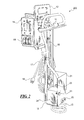
- FIG. 2 is a perspective view of the improved parts washer module as shown in FIG. I according to a first embodiment of the present disclosure with a pump having a horizontal inlet and a vertical outlet next to a plenum.
- FIG. 3 is an exploded perspective view of the improved parts washer module as shown in FIG. 2 according to a first embodiment of the present disclosure.
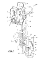
- FIG. 4 is a perspective view of an improved parts washer module according to a second embodiment of the present disclosure equipped with a pump having a horizontal outlet and a vertical inlet.
- FIG. 5 is an exploded view of the improved parts washer module as shown in FIG. 4 according to a second embodiment of the present disclosure.
- FIG. 6 is a perspective view of an improved parts washer with a rectangular reservoir constructed in accordance with another embodiment of the present disclosure.
- the improved parts washer of the present disclosure is primarily for use in connection with parts washing operations in commercial and industrial applications.
- the present disclosure relates generally to improvements to an apparatus for washing parts, called commonly a "parts washer," using a cleaning fluid. While the hereafter proposed improvements constitute genuine improvements over the prior art, they cannot be construed in any way, shape, or form as limiting any of the novel and inventive subject matter previously disclosed and incorporated herein by reference.
- the new and novel inventive features described hereafter are nonobvious improvements over these references and also should not be reviewed with the benefit of hindsight. Since previous patents relating to parts washer are hereby incorporated by reference, conflicting or additional disclosure herein relating to elements must be construed when possible as coherent and additional disclosure. In the case of conflicting disclosure, this disclosure is to be given specific meaning and the incorporated disclosures shall be given general meaning when possible.
- the present disclosure relates generally to improvements to an apparatus for washing parts using a cleaning fluid, including but are not limited to magnets located near a pump inlet to collect metallic particles suspended in the cleaning fluid, the magnets placed in one preferred embodiment outside of the casing; a casing to protect the pump mechanism from impact during handling and to create a plenum space between the pump and the casing; a horizontal orientation of the pump and/or of the pump inlet to take advantage of the sedimentation of debris in the cleaning fluid; the use of two liquid level sensors to measure the level of the cleaning fluid in the reservoir; an evaporation control plate located at the interface between the reservoir and the receptacle to confine the vapor portion of the cleaning solution within the reservoir; two protective handlebars placed next to the controls of a control module or a molded edge in the control module casing to protect the device from impact; and a pulsating flow pump to warn a user of a low fluid level within the reservoir.
- magnets located near a pump inlet to collect metallic particles suspended in the cleaning fluid, the magnets
- FIG. 1 shows a perspective view of the improved parts washer 100 constructed in accordance with an embodiment of the present disclosure.
- the parts washer 100 is used for washing mechanical parts and may include a receptacle 1 connected on a reservoir 2 for containing a cleaning fluid 3, a drain opening (not shown) defined in the receptacle 1 for fluid communication between the receptacle 1 and the reservoir 2, and what is described as a whole as an improved parts washer module 200.
- a user may carry or transport with the aid of a mechanical device the receptacle 1, the reservoir 2, and the parts washer module 200 to a worksite where parts are cleaned using the parts washer 100.
- the parts washer 100 is connected using an electrical cable 17 to a power outlet (not shown).
- the parts washer module 200 as shown in FIG. 1 may include a control module 14, a handle 12, a frame 13, a pump 10, a heating element 15, and their associated mechanical, functional, and electrical connections as described hereafter.
- the parts washer module 200 may also include a liquid level detector 16 as shown in FIGS. 2 and 3, a first sensor 19, a second sensor 20, and a protective guard 21 for the pump 10 or the magnets 22.
- the receptacle 1 shown in FIG. 1 may be a commercial sink made of stainless steel, plastic, or other robust material.
- the receptacle 1 may include plural, preferably tapered sidewalls 5, an upper peripheral margin 6, and a rear margin 7 of increased width to which a back wall 4 may be attached.
- a light 8 may be used to help the operator (not shown) during parts washing. While a receptacle 1 of rectangular geometry with a flat bottom section is shown in FIG. 1, but what is contemplated is any receptacle 1 of any useful geometry designed to hold a cleaning fluid in accordance with the principles of this disclosure.
- FIG. 6 is a perspective view of an improved parts washer with a rectangular reservoir constructed in accordance with another embodiment of the present disclosure.
- a light 8 and a back wall 4 attached to the receptacle 1 to transform the receptacle area into a work area where an operator (not shown) can clean parts with improved visibility.
- the back wall 4 is attached to the receptacle 1 using hinges, but other types of fixation devices including but not limited to clips, welds, slide rails, bolts, etc. are also contemplated.
- any type of device or system used in work areas including but not limited to a work area with different elements for holding and storing tools and documents, storing or using secondary cleaning products, communication devices, and control terminals for operation of the parts washer or management of work performed in the work area.
- the drain (not shown) between the receptacle I and the reservoir 2 is implied within the definition of the receptacle 1 or sink. Any type of drain (not shown), including a plug or other drain restriction or drain filtration device, is contemplated. What is also contemplated is the use of racks, strainers, holders, and curvatures made in the receptacle 1 to manage the use of the cleaning fluid 3 within the receptacle 1. By way of nonlimiting example, what is also contemplated is the use of lateral slits as drains made at a certain height within the receptacle 1 to maintain a volume of cleaning fluid at the bottom or the receptacle 1 where parts can be soaked.
- FIG. 2 of U.S. Patent No. 7,040,161 shows a contemplated example associated with the methods of controlling the flow of cleaning fluid from the reservoir 2 to the receptacle 1. This figure shows the device where a user-selectable valve is used along with a hose connector and brush.
- FIG. 1 of the current disclosure shows a configuration where the connection between end 11 of the output hose 9 of the pump 10 is not connected to any user-controlled valve. While one possible embodiment is shown where the end 11 of the output hose 9 must be attached to the flow control device, such as a nozzle, a user-selectable valve, a hose, or any other type of connector, it is understood by one of ordinary skill in the art that the use of any configuration where a pump 10 moves cleaning fluid to an output hose 9 may be used.
- the flow control device such as a nozzle, a user-selectable valve, a hose, or any other type of connector
- the parts washer module 200 as illustrated in FIG. 1 is attached to the interface between the reservoir 2 and the receptacle 1. It is understood that the parts washer module 200 comprises a handle 12 for handling, holding, raising, and securing the parts washer module 200 in place.
- the parts washer module 200 is attached to the reservoir 2 in a counterweight fashion.
- a first portion of a frame 13 of the parts washer module 200 equipped with the pump 10, the heating element 15, and the liquid level detector 16 as shown in FIG. 2 is placed inside of the reservoir 2 and is in contact with the cleaning fluid 3. Absent a counterweight, the frame 13 would be able to move within the reservoir 2.
- the control module 14 is attached to a second section of the frame 13 located outside of the reservoir 2.
- any displacement of the inner or outer sections of the frame 13 must correspond to an associated displacement of the other counterweight section. For example, if the command module is lifted at its base from the interface between the reservoir 2 and the receptacle 1, then the pump is blocked internally by the reservoir 2. While one method of fixation and stabilization of the frame 13 is shown, what is contemplated within the scope of this disclosure is any method of fixing the frame 13 or of the different constituents of the parts washer module 200 on the reservoir 2, including but not limited to vertical supports, radial supports, mechanical fixation means, or use of a reservoir with fixation openings, magnets, clamps, etc.
- FIGS. 1-3 illustrate one possible type of pump 10 for moving the cleaning fluid 3 from the reservoir 2 to the receptacle 1 at a flow rate.
- FIGS. 4-5 illustrate a second possible embodiment where the pump 110 is designed to move the cleaning fluid 3 from the reservoir 2 to the receptacle 1 at a flow rate. While two different types of pumps 10, 110 are shown, what is contemplated is the use of any type of pump able to move the cleaning fluid 3 from the reservoir 2 to the receptacle 1.
- FIG. 3 is an exploded view of the pump 10 with a pump outlet 23 located above the pump 10 and an electrical connection 24 located in the back of the pump 10 shown in FIG. 3 as the front of the illustration.
- FIG. 5 is an exploded view of the pump 110 with a pump outlet 123 located on the front of the pump 110 and an electrical connection 124 located on top of the pump 110.
- Both types of pumps 10, 110 may be equipped in the preferred embodiments with a protective guard 21, 121, shown as a C-shaped metal casing with a front wall 25, 125, a back wall 26, 126, and a fixation wall 27, 127.
- the pump 10 in FIG. 3 is held by a lower plate 28, while the pump 110 in FIG. 5 is held by an intermediate plate 128.
- Both plates 28, 128 serve to hold the pumps 10, 110 while allowing the cleaning fluid 3 access to the pump inlet (not shown).
- a filter 130 is shown in FIG. 5, which protects the pump inlet from large debris and other particles suspended in the cleaning fluid 3.
- An indirect filter is created in the plenum area in front of the pump 10 at the inlet by the volume contained within the protective guard 21 and the lower plate 28.
- Pump 10 is horizontally oriented with a vertical outlet 23 and a horizontal inlet (not shown).
- Pump 110 is vertically oriented with a vertical inlet and a horizontal outlet 123.
- magnetized blocks 22, 122 located outside the protective guard 21, 121 as shown in FIGS. 3 and 5. What is shown is only one possible embodiment, and what is contemplated is the placement of magnetized blocks 22, 122 in the passage of the cleaning fluid 3 next to the pump inlets (not shown) outside of the protective guard 21, 121.
- the use of magnetized blocks 22, 122 allows for the collection of magnetized particles or materials with magnetic properties suspended in the cleaning fluid 3, such as chips of metal and the like.
- the protective guard 21 is also equipped with a lower plate 28 with slide rails to be used in conjunction with a securing screw 31 also called a securing knob.
- a securing screw 31 also called a securing knob.
- This system allows for displacement of the pump 10 inside of the protective guard 21 in order to create a plenum area where cleaning fluid to be pumped can flow absent debris.
- the intermediate plate 128 of pump 110 as shown in FIG. 5 includes an opening to allow for the bottom section of the pump and the filter 130 to pass unobstructed.
- FIG. 3 also illustrates the liquid level detector 16 disposed within the reservoir 2 for generating a first signal, generally an electrical signal using a first sensor 19, when the cleaning fluid 3 shown in FIG. 1 is disposed at least at a predetermined level generally associated with the position of the first sensor 19 on the liquid level detector 16.
- the first sensor 19 is located at an intermediate junction
- the second sensor 20 is located at a lower end on the liquid level detector 16.
- the second signal is generated when the cleaning fluid 3 is disposed below the first predetermined level below this level.
- the control module 14 is connected to the pumps 10, 110 and to the liquid level detector 16 for receiving one of the first and second signals from the sensors 19, 20.
- the control module 14 allows the pump 10, 110 to work in a pulsating fashion and create a pulsating flow of cleaning fluid 3 in the receptacle 1 upon reaching the first or second sensors 19, 20 on the liquid level detector 16. Both the first and second sensors 19, 20 are also able to monitor the level of the cleaning fluid 3 in the reservoir to turn off the heating element 15 if the cleaning fluid 3 reaches a low level where the heating element 15 can sustain damage by not being sufficiently submerged.
- the pumps 10, 110 pulsate to create an artificial variability of the flow rate.
- the liquid level detector is a commercial thermistor.
- the liquid level detector 16 includes a pair of thermistors oriented on intersecting axes on a T-shaped head.
- the use of the pump 110 in a vertical orientation as shown in FIGS. 4-5 allows for the preferential pumping of the top layers of cleaning fluid 3, which are less subject to high content of dirt or other particles in suspension.
- the pump 10 while horizontal draws from the plenum used with the lower plate 28 to draw only the top layer of the cleaning fluid 3 or draw fluid from upper layers that may flow from the back of the pump 10 to the front of the pump 10.
- interface plate 37 is connected to the interface between the reservoir 2 and the receptacle 1 as shown in FIGS. 3 and 5, respectively, to prevent evaporation of the cleaning fluid 3 located inside the reservoir 2.
- the interface plate 37 may be snapped or locked in place either on the parts washer module 200 or at that interface between the reservoir 2 and the receptacle 1-
- FIGS. 3 and 5 show the use of locking arms 38 that allows the interface plate 37 to be inserted and locked into position. What is also shown is the removal of part of the outer section of the interface plate 37 to allow for the passage in a preferred embodiment of the heating element 15 and the liquid level detector 16.
- the interface plate 37 is in the shape of a segment of a circle, but it is understood by one of ordinary skill in the art that the shape of the interface plate 37 is based on the interstitial opening space created at the junction of the reservoir 2 and the receptacle 1. What is also contemplated is the use of other interface plates located in other orientations around the receptacle in the eventuality that other interstitial openings between the reservoir 2 and the receptacle 1 are present. It is understood by one of ordinary skill in the art that what is contemplated by way of this disclosure is the use of interface plates to prevent evaporation of the cleaning fluid 3 from the reservoir 2.
- a marking such as the word "top,” is used to distinguish between the upper surface of the interface plate and the lower surface of the interface plate. But it is understood that any marking in any language including symbols, pictograms, and other recognizable markings may be used.
- the frame 13 includes a pump 10 disposed in the reservoir 2 and connected to the frame 13 for moving the cleaning fluid 3 from the reservoir 2 to the receptacle 1 at a flow rate, a heating element 15 disposed within the reservoir 2 and connected to the frame 13 in fluid contact with the cleaning fluid 3 in the reservoir 2 for heating the cleaning fluid, and a control module 14 comprising in one embodiment a pair of handlebars 60 as shown in FIGS. 2 and 4 and a series of controls 61 for activating the lamp 8, the heating element 15, and the pump 10, wherein the handlebars 60 are disposed adjacent the series of controls 61 to protect the series of controls 61 from impact.
- control module 14 comprises one handlebar 60, which act as roll-bar, which may also be used to handle the parts washer 100 or the parts washer module 200.
- the handlebars 60 may also be molded within the casing of the control module 14.
- handlebars 60 instead of handlebars 60, what is contemplated is the use of molded edges made in the control module 14 casing to protect the series of controls 61. While one possible method of protection is shown and illustrated, what is contemplated is the use of any device either built-in or added that allows the series of controls 61 to be protected from impact.
- FIG. 1 also shows the heating element 15 used to heat the cleaning solution 3 within the reservoir 2, the heating element 15 being made of a single-coil heater connected to the control module 14 and curved to provide better heating locally at the input (not shown) of the pump 10.
- These improvements include but are not limited to the use of magnets located near a pump inlet to collect metallic particles suspended in the cleaning fluid, which metallic particles are capable of damaging the inside of the pump during circulation; a casing to protect the pump mechanism from impact during handling and to create a plenum area; a horizontal orientation of the pump to take advantage of the separation of the cleaning fluid in successive vertical layers or the use of a vertical orientation pump that acts with a plenum area to take advantage of the separation of the cleaning fluid in successive vertical layers; the use of two liquid level sensors to measure the level of the cleaning fluid in the reservoir and ultimately control the heating element; an evaporation control plate located at the upper rim of the reservoir to confine the vapor portion of the cleaning solution; protective handlebars placed next to the controls of a control module or molded edges in the protective casing of the control module to protect the device from impact; and a segmented pump motor control to create a pulsating flow to warn a user of a low level of cleaning fluid within the reservoir.
Landscapes
- Physics & Mathematics (AREA)
- Fluid Mechanics (AREA)
- General Physics & Mathematics (AREA)
- Cleaning By Liquid Or Steam (AREA)
- Cleaning And De-Greasing Of Metallic Materials By Chemical Methods (AREA)
- Structures Of Non-Positive Displacement Pumps (AREA)
- Cooling Or The Like Of Electrical Apparatus (AREA)
- Cooling Or The Like Of Semiconductors Or Solid State Devices (AREA)
Applications Claiming Priority (1)
| Application Number | Priority Date | Filing Date | Title |
|---|---|---|---|
| US11/556,087 US7740711B2 (en) | 2006-11-02 | 2006-11-02 | Parts washer heater pump module |
Publications (3)
| Publication Number | Publication Date |
|---|---|
| EP1918028A2 true EP1918028A2 (de) | 2008-05-07 |
| EP1918028A3 EP1918028A3 (de) | 2008-06-11 |
| EP1918028B1 EP1918028B1 (de) | 2010-01-06 |
Family
ID=39032207
Family Applications (1)
| Application Number | Title | Priority Date | Filing Date |
|---|---|---|---|
| EP07117085A Not-in-force EP1918028B1 (de) | 2006-11-02 | 2007-09-24 | Wärmepumpenmodul für eine Teilewaschvorrichtung |
Country Status (11)
| Country | Link |
|---|---|
| US (1) | US7740711B2 (de) |
| EP (1) | EP1918028B1 (de) |
| JP (2) | JP2008114221A (de) |
| KR (1) | KR20080040567A (de) |
| CN (1) | CN101172276B (de) |
| AT (1) | ATE454226T1 (de) |
| CA (1) | CA2604283C (de) |
| DE (1) | DE602007004161D1 (de) |
| ES (1) | ES2338059T3 (de) |
| IL (1) | IL186797A0 (de) |
| MX (1) | MX2007013220A (de) |
Cited By (1)
| Publication number | Priority date | Publication date | Assignee | Title |
|---|---|---|---|---|
| FR3040315A1 (fr) * | 2015-09-01 | 2017-03-03 | Cemex Res Group Ag | Dispositif pour la recuperation de l'eau de lavage d'un camion beton |
Families Citing this family (8)
| Publication number | Priority date | Publication date | Assignee | Title |
|---|---|---|---|---|
| US7740711B2 (en) * | 2006-11-02 | 2010-06-22 | Safety-Kleen Systems, Inc. | Parts washer heater pump module |
| US9976290B2 (en) | 2015-01-19 | 2018-05-22 | Moen Incorporated | Electronic plumbing fixture fitting with flow module |
| US10610904B2 (en) * | 2015-08-06 | 2020-04-07 | David Jonathan Tafoya | Removal of soluble support material with flow control |
| CN108435744B (zh) * | 2018-03-27 | 2020-05-19 | 昆山国显光电有限公司 | 金属颗粒收集装置及金属颗粒收集系统 |
| CN112845396B (zh) * | 2021-01-08 | 2022-12-06 | 江苏佳佩环保机械设备有限公司 | 一种树池格栅板深度清洁装置 |
| CN114798577B (zh) * | 2022-04-12 | 2023-10-03 | 昆山宝兴精密五金有限公司 | 一种精密复合丝攻的加工装置及方法 |
| US12569889B1 (en) * | 2022-09-09 | 2026-03-10 | Alliance Manufacturing, Inc. | Gas heating system for a parts washing machine, and to the method of converting an electric parts washing machine to a gas parts washing machine |
| US12539529B2 (en) * | 2023-01-29 | 2026-02-03 | Ronald Bluestone | Combination parts jet washer and sink washer with parts washer with minimum grip sprocket drive system |
Citations (4)
| Publication number | Priority date | Publication date | Assignee | Title |
|---|---|---|---|---|
| US5598861A (en) | 1995-03-07 | 1997-02-04 | Safety-Kleen Corp. | Parts washer with solvent flow control |
| US6095163A (en) | 1994-09-30 | 2000-08-01 | Chemfree Corporation | Parts washing system |
| US20020170978A1 (en) | 2001-05-16 | 2002-11-21 | Mohn Merrill K. | Paint gun washer |
| US20040200504A1 (en) | 2003-04-10 | 2004-10-14 | Rudy Publ | Parts washer with improved temperature & pump control |
Family Cites Families (18)
| Publication number | Priority date | Publication date | Assignee | Title |
|---|---|---|---|---|
| US3522814A (en) * | 1968-12-06 | 1970-08-04 | Safety Kleen Corp | Washer for parts and the like |
| US5213119A (en) * | 1986-03-20 | 1993-05-25 | Safety-Kleen Corporation | Solvent recirculating type spray gun cleaner |
| US5232299A (en) * | 1992-07-21 | 1993-08-03 | Better Engineering Mfg., Inc. | Parts washer |
| JPH078729U (ja) * | 1993-07-20 | 1995-02-07 | 清彦 三嘴 | 水位センサー |
| US6571810B1 (en) * | 1994-09-30 | 2003-06-03 | Zymo International, Inc. | Parts washing system |
| US6328045B1 (en) * | 1994-09-30 | 2001-12-11 | Chemfree Corporation | Parts washing system |
| US5827374A (en) * | 1995-02-24 | 1998-10-27 | Mansur Industries Inc. | Process for integrated recycling of cleaning solution in industrial washing equipment |
| US5720308A (en) * | 1995-03-07 | 1998-02-24 | Safety Kleen Corp. | Parts washer with solvent flow control |
| US6016818A (en) * | 1996-07-18 | 2000-01-25 | Nch Corporation | Recirculating parts washer |
| US6109277A (en) * | 1996-09-10 | 2000-08-29 | Landa, Inc. | Parts washer |
| US5954071A (en) * | 1997-01-15 | 1999-09-21 | Magliocca; Charles Thomas | Parts washing apparatus with centrifugal filter |
| US6199565B1 (en) * | 1998-11-05 | 2001-03-13 | Ronald H. Bluestone | Modular parts washing apparatus and servicing method |
| US5950647A (en) * | 1998-11-18 | 1999-09-14 | Usher Oil Company | Parts washing apparatus |
| US6279587B1 (en) * | 1999-04-12 | 2001-08-28 | Soichiro Yamamoto | Parts washer with solvent recycling |
| JP2002336176A (ja) * | 2001-05-17 | 2002-11-26 | Hoshizaki Electric Co Ltd | 食器洗浄装置 |
| DE10213433A1 (de) * | 2002-03-26 | 2003-10-23 | Bosch Gmbh Robert | Entfernungsmeßgerät mit einer Zieleinrichtung |
| JP2005134230A (ja) * | 2003-10-30 | 2005-05-26 | Fuji Electric Retail Systems Co Ltd | 液位検知装置 |
| US7740711B2 (en) * | 2006-11-02 | 2010-06-22 | Safety-Kleen Systems, Inc. | Parts washer heater pump module |
-
2006
- 2006-11-02 US US11/556,087 patent/US7740711B2/en active Active
-
2007
- 2007-09-24 EP EP07117085A patent/EP1918028B1/de not_active Not-in-force
- 2007-09-24 AT AT07117085T patent/ATE454226T1/de not_active IP Right Cessation
- 2007-09-24 DE DE602007004161T patent/DE602007004161D1/de active Active
- 2007-09-24 ES ES07117085T patent/ES2338059T3/es active Active
- 2007-09-26 CA CA2604283A patent/CA2604283C/en active Active
- 2007-10-15 KR KR1020070103403A patent/KR20080040567A/ko not_active Ceased
- 2007-10-18 IL IL186797A patent/IL186797A0/en not_active IP Right Cessation
- 2007-10-23 MX MX2007013220A patent/MX2007013220A/es active IP Right Grant
- 2007-10-29 CN CN2007101675004A patent/CN101172276B/zh not_active Expired - Fee Related
- 2007-10-29 JP JP2007280469A patent/JP2008114221A/ja active Pending
-
2012
- 2012-03-06 JP JP2012048884A patent/JP2012110896A/ja not_active Ceased
Patent Citations (4)
| Publication number | Priority date | Publication date | Assignee | Title |
|---|---|---|---|---|
| US6095163A (en) | 1994-09-30 | 2000-08-01 | Chemfree Corporation | Parts washing system |
| US5598861A (en) | 1995-03-07 | 1997-02-04 | Safety-Kleen Corp. | Parts washer with solvent flow control |
| US20020170978A1 (en) | 2001-05-16 | 2002-11-21 | Mohn Merrill K. | Paint gun washer |
| US20040200504A1 (en) | 2003-04-10 | 2004-10-14 | Rudy Publ | Parts washer with improved temperature & pump control |
Cited By (1)
| Publication number | Priority date | Publication date | Assignee | Title |
|---|---|---|---|---|
| FR3040315A1 (fr) * | 2015-09-01 | 2017-03-03 | Cemex Res Group Ag | Dispositif pour la recuperation de l'eau de lavage d'un camion beton |
Also Published As
| Publication number | Publication date |
|---|---|
| CN101172276B (zh) | 2012-09-05 |
| JP2008114221A (ja) | 2008-05-22 |
| ES2338059T3 (es) | 2010-05-03 |
| CA2604283C (en) | 2014-12-30 |
| JP2012110896A (ja) | 2012-06-14 |
| CN101172276A (zh) | 2008-05-07 |
| EP1918028A3 (de) | 2008-06-11 |
| ATE454226T1 (de) | 2010-01-15 |
| KR20080040567A (ko) | 2008-05-08 |
| MX2007013220A (es) | 2009-02-18 |
| CA2604283A1 (en) | 2008-05-02 |
| US20080105285A1 (en) | 2008-05-08 |
| HK1117788A1 (en) | 2009-01-23 |
| DE602007004161D1 (de) | 2010-02-25 |
| EP1918028B1 (de) | 2010-01-06 |
| US7740711B2 (en) | 2010-06-22 |
| IL186797A0 (en) | 2009-02-11 |
Similar Documents
| Publication | Publication Date | Title |
|---|---|---|
| CA2604283C (en) | Parts washer heater pump module | |
| EP2006036B1 (de) | Wascher für bewegliche Spülbeckenteile | |
| US8220471B2 (en) | Multipurpose aqueous parts washer | |
| JP5051772B2 (ja) | 多目的水系部品洗浄装置 | |
| DK2415532T3 (en) | Component washing apparatus and method for washing components | |
| CN102105235B (zh) | 储存箱清理方法和设备 | |
| US6199565B1 (en) | Modular parts washing apparatus and servicing method | |
| CN102015130A (zh) | 多用途零件水清洗机 | |
| US4503577A (en) | Pipe and hose decontamination apparatus | |
| US4317720A (en) | Cleaning fluid recovery apparatus | |
| HK1117788B (en) | Parts washer heater pump module | |
| US5482061A (en) | Wash system | |
| US20210101803A1 (en) | Portable fluid collection and filtration system | |
| US20140174479A1 (en) | Parts washer assembly with clean rinse module | |
| CN219290741U (zh) | 一种油渣分离箱 | |
| US20140209130A1 (en) | Mobile sanitary wash system and apparatus | |
| Chace et al. | Cleaning Parts Washing Baths | |
| JPH02103288A (ja) | 切削油の再生処理方法及び再生処理装置 | |
| AU1648599A (en) | Article cleaning apparatus |
Legal Events
| Date | Code | Title | Description |
|---|---|---|---|
| PUAI | Public reference made under article 153(3) epc to a published international application that has entered the european phase |
Free format text: ORIGINAL CODE: 0009012 |
|
| AK | Designated contracting states |
Kind code of ref document: A2 Designated state(s): AT BE BG CH CY CZ DE DK EE ES FI FR GB GR HU IE IS IT LI LT LU LV MC MT NL PL PT RO SE SI SK TR |
|
| AX | Request for extension of the european patent |
Extension state: AL BA HR MK RS |
|
| PUAL | Search report despatched |
Free format text: ORIGINAL CODE: 0009013 |
|
| AK | Designated contracting states |
Kind code of ref document: A3 Designated state(s): AT BE BG CH CY CZ DE DK EE ES FI FR GB GR HU IE IS IT LI LT LU LV MC MT NL PL PT RO SE SI SK TR |
|
| AX | Request for extension of the european patent |
Extension state: AL BA HR MK RS |
|
| 17P | Request for examination filed |
Effective date: 20081204 |
|
| AKX | Designation fees paid |
Designated state(s): AT BE BG CH CY CZ DE DK EE ES FI FR GB GR HU IE IS IT LI LT LU LV MC MT NL PL PT RO SE SI SK TR |
|
| 17Q | First examination report despatched |
Effective date: 20090212 |
|
| GRAP | Despatch of communication of intention to grant a patent |
Free format text: ORIGINAL CODE: EPIDOSNIGR1 |
|
| GRAS | Grant fee paid |
Free format text: ORIGINAL CODE: EPIDOSNIGR3 |
|
| GRAA | (expected) grant |
Free format text: ORIGINAL CODE: 0009210 |
|
| AK | Designated contracting states |
Kind code of ref document: B1 Designated state(s): AT BE BG CH CY CZ DE DK EE ES FI FR GB GR HU IE IS IT LI LT LU LV MC MT NL PL PT RO SE SI SK TR |
|
| REG | Reference to a national code |
Ref country code: GB Ref legal event code: FG4D |
|
| REG | Reference to a national code |
Ref country code: CH Ref legal event code: EP |
|
| REG | Reference to a national code |
Ref country code: IE Ref legal event code: FG4D |
|
| REF | Corresponds to: |
Ref document number: 602007004161 Country of ref document: DE Date of ref document: 20100225 Kind code of ref document: P |
|
| REG | Reference to a national code |
Ref country code: ES Ref legal event code: FG2A Ref document number: 2338059 Country of ref document: ES Kind code of ref document: T3 |
|
| REG | Reference to a national code |
Ref country code: NL Ref legal event code: VDEP Effective date: 20100106 |
|
| REG | Reference to a national code |
Ref country code: GR Ref legal event code: EP Ref document number: 20100400826 Country of ref document: GR |
|
| PG25 | Lapsed in a contracting state [announced via postgrant information from national office to epo] |
Ref country code: SI Free format text: LAPSE BECAUSE OF FAILURE TO SUBMIT A TRANSLATION OF THE DESCRIPTION OR TO PAY THE FEE WITHIN THE PRESCRIBED TIME-LIMIT Effective date: 20100106 |
|
| LTIE | Lt: invalidation of european patent or patent extension |
Effective date: 20100106 |
|
| PG25 | Lapsed in a contracting state [announced via postgrant information from national office to epo] |
Ref country code: AT Free format text: LAPSE BECAUSE OF FAILURE TO SUBMIT A TRANSLATION OF THE DESCRIPTION OR TO PAY THE FEE WITHIN THE PRESCRIBED TIME-LIMIT Effective date: 20100106 |
|
| PG25 | Lapsed in a contracting state [announced via postgrant information from national office to epo] |
Ref country code: IS Free format text: LAPSE BECAUSE OF FAILURE TO SUBMIT A TRANSLATION OF THE DESCRIPTION OR TO PAY THE FEE WITHIN THE PRESCRIBED TIME-LIMIT Effective date: 20100506 Ref country code: PT Free format text: LAPSE BECAUSE OF FAILURE TO SUBMIT A TRANSLATION OF THE DESCRIPTION OR TO PAY THE FEE WITHIN THE PRESCRIBED TIME-LIMIT Effective date: 20100506 Ref country code: LT Free format text: LAPSE BECAUSE OF FAILURE TO SUBMIT A TRANSLATION OF THE DESCRIPTION OR TO PAY THE FEE WITHIN THE PRESCRIBED TIME-LIMIT Effective date: 20100106 Ref country code: NL Free format text: LAPSE BECAUSE OF FAILURE TO SUBMIT A TRANSLATION OF THE DESCRIPTION OR TO PAY THE FEE WITHIN THE PRESCRIBED TIME-LIMIT Effective date: 20100106 |
|
| PG25 | Lapsed in a contracting state [announced via postgrant information from national office to epo] |
Ref country code: FI Free format text: LAPSE BECAUSE OF FAILURE TO SUBMIT A TRANSLATION OF THE DESCRIPTION OR TO PAY THE FEE WITHIN THE PRESCRIBED TIME-LIMIT Effective date: 20100106 Ref country code: LV Free format text: LAPSE BECAUSE OF FAILURE TO SUBMIT A TRANSLATION OF THE DESCRIPTION OR TO PAY THE FEE WITHIN THE PRESCRIBED TIME-LIMIT Effective date: 20100106 Ref country code: PL Free format text: LAPSE BECAUSE OF FAILURE TO SUBMIT A TRANSLATION OF THE DESCRIPTION OR TO PAY THE FEE WITHIN THE PRESCRIBED TIME-LIMIT Effective date: 20100106 |
|
| PG25 | Lapsed in a contracting state [announced via postgrant information from national office to epo] |
Ref country code: RO Free format text: LAPSE BECAUSE OF FAILURE TO SUBMIT A TRANSLATION OF THE DESCRIPTION OR TO PAY THE FEE WITHIN THE PRESCRIBED TIME-LIMIT Effective date: 20100106 Ref country code: EE Free format text: LAPSE BECAUSE OF FAILURE TO SUBMIT A TRANSLATION OF THE DESCRIPTION OR TO PAY THE FEE WITHIN THE PRESCRIBED TIME-LIMIT Effective date: 20100106 Ref country code: CY Free format text: LAPSE BECAUSE OF FAILURE TO SUBMIT A TRANSLATION OF THE DESCRIPTION OR TO PAY THE FEE WITHIN THE PRESCRIBED TIME-LIMIT Effective date: 20100106 Ref country code: SE Free format text: LAPSE BECAUSE OF FAILURE TO SUBMIT A TRANSLATION OF THE DESCRIPTION OR TO PAY THE FEE WITHIN THE PRESCRIBED TIME-LIMIT Effective date: 20100106 Ref country code: BE Free format text: LAPSE BECAUSE OF FAILURE TO SUBMIT A TRANSLATION OF THE DESCRIPTION OR TO PAY THE FEE WITHIN THE PRESCRIBED TIME-LIMIT Effective date: 20100106 |
|
| PLBE | No opposition filed within time limit |
Free format text: ORIGINAL CODE: 0009261 |
|
| STAA | Information on the status of an ep patent application or granted ep patent |
Free format text: STATUS: NO OPPOSITION FILED WITHIN TIME LIMIT |
|
| PG25 | Lapsed in a contracting state [announced via postgrant information from national office to epo] |
Ref country code: CZ Free format text: LAPSE BECAUSE OF FAILURE TO SUBMIT A TRANSLATION OF THE DESCRIPTION OR TO PAY THE FEE WITHIN THE PRESCRIBED TIME-LIMIT Effective date: 20100106 Ref country code: BG Free format text: LAPSE BECAUSE OF FAILURE TO SUBMIT A TRANSLATION OF THE DESCRIPTION OR TO PAY THE FEE WITHIN THE PRESCRIBED TIME-LIMIT Effective date: 20100406 Ref country code: SK Free format text: LAPSE BECAUSE OF FAILURE TO SUBMIT A TRANSLATION OF THE DESCRIPTION OR TO PAY THE FEE WITHIN THE PRESCRIBED TIME-LIMIT Effective date: 20100106 |
|
| 26N | No opposition filed |
Effective date: 20101007 |
|
| PG25 | Lapsed in a contracting state [announced via postgrant information from national office to epo] |
Ref country code: DK Free format text: LAPSE BECAUSE OF FAILURE TO SUBMIT A TRANSLATION OF THE DESCRIPTION OR TO PAY THE FEE WITHIN THE PRESCRIBED TIME-LIMIT Effective date: 20100106 |
|
| PG25 | Lapsed in a contracting state [announced via postgrant information from national office to epo] |
Ref country code: MC Free format text: LAPSE BECAUSE OF NON-PAYMENT OF DUE FEES Effective date: 20100930 |
|
| PG25 | Lapsed in a contracting state [announced via postgrant information from national office to epo] |
Ref country code: MT Free format text: LAPSE BECAUSE OF FAILURE TO SUBMIT A TRANSLATION OF THE DESCRIPTION OR TO PAY THE FEE WITHIN THE PRESCRIBED TIME-LIMIT Effective date: 20100106 |
|
| REG | Reference to a national code |
Ref country code: CH Ref legal event code: PL |
|
| PG25 | Lapsed in a contracting state [announced via postgrant information from national office to epo] |
Ref country code: LI Free format text: LAPSE BECAUSE OF NON-PAYMENT OF DUE FEES Effective date: 20110930 Ref country code: CH Free format text: LAPSE BECAUSE OF NON-PAYMENT OF DUE FEES Effective date: 20110930 |
|
| PG25 | Lapsed in a contracting state [announced via postgrant information from national office to epo] |
Ref country code: HU Free format text: LAPSE BECAUSE OF FAILURE TO SUBMIT A TRANSLATION OF THE DESCRIPTION OR TO PAY THE FEE WITHIN THE PRESCRIBED TIME-LIMIT Effective date: 20100707 Ref country code: LU Free format text: LAPSE BECAUSE OF NON-PAYMENT OF DUE FEES Effective date: 20100924 |
|
| PG25 | Lapsed in a contracting state [announced via postgrant information from national office to epo] |
Ref country code: TR Free format text: LAPSE BECAUSE OF FAILURE TO SUBMIT A TRANSLATION OF THE DESCRIPTION OR TO PAY THE FEE WITHIN THE PRESCRIBED TIME-LIMIT Effective date: 20100106 |
|
| REG | Reference to a national code |
Ref country code: FR Ref legal event code: CA Effective date: 20130523 |
|
| REG | Reference to a national code |
Ref country code: DE Ref legal event code: R082 Ref document number: 602007004161 Country of ref document: DE Representative=s name: W.P.THOMPSON & CO., GB Effective date: 20130718 Ref country code: DE Ref legal event code: R081 Ref document number: 602007004161 Country of ref document: DE Owner name: SAFETY-KLEEN SYSTEMS INC., US Free format text: FORMER OWNER: SAFETY-KLEEN SYSTEMS INC., PLANO, US Effective date: 20130718 Ref country code: DE Ref legal event code: R081 Ref document number: 602007004161 Country of ref document: DE Owner name: SAFETY-KLEEN SYSTEMS INC., NORWELL, US Free format text: FORMER OWNER: SAFETY-KLEEN SYSTEMS INC., PLANO, TEX., US Effective date: 20130718 |
|
| PGFP | Annual fee paid to national office [announced via postgrant information from national office to epo] |
Ref country code: IE Payment date: 20130829 Year of fee payment: 7 Ref country code: ES Payment date: 20130912 Year of fee payment: 7 Ref country code: GR Payment date: 20130828 Year of fee payment: 7 |
|
| PGFP | Annual fee paid to national office [announced via postgrant information from national office to epo] |
Ref country code: GB Payment date: 20130827 Year of fee payment: 7 Ref country code: FR Payment date: 20130826 Year of fee payment: 7 |
|
| PGFP | Annual fee paid to national office [announced via postgrant information from national office to epo] |
Ref country code: IT Payment date: 20130919 Year of fee payment: 7 |
|
| PGFP | Annual fee paid to national office [announced via postgrant information from national office to epo] |
Ref country code: DE Payment date: 20130930 Year of fee payment: 7 |
|
| REG | Reference to a national code |
Ref country code: DE Ref legal event code: R119 Ref document number: 602007004161 Country of ref document: DE |
|
| REG | Reference to a national code |
Ref country code: GR Ref legal event code: ML Ref document number: 20100400826 Country of ref document: GR Effective date: 20150403 |
|
| GBPC | Gb: european patent ceased through non-payment of renewal fee |
Effective date: 20140924 |
|
| REG | Reference to a national code |
Ref country code: IE Ref legal event code: MM4A |
|
| REG | Reference to a national code |
Ref country code: FR Ref legal event code: ST Effective date: 20150529 |
|
| PG25 | Lapsed in a contracting state [announced via postgrant information from national office to epo] |
Ref country code: DE Free format text: LAPSE BECAUSE OF NON-PAYMENT OF DUE FEES Effective date: 20150401 Ref country code: GB Free format text: LAPSE BECAUSE OF NON-PAYMENT OF DUE FEES Effective date: 20140924 |
|
| PG25 | Lapsed in a contracting state [announced via postgrant information from national office to epo] |
Ref country code: FR Free format text: LAPSE BECAUSE OF NON-PAYMENT OF DUE FEES Effective date: 20140930 Ref country code: GR Free format text: LAPSE BECAUSE OF NON-PAYMENT OF DUE FEES Effective date: 20150403 Ref country code: IE Free format text: LAPSE BECAUSE OF NON-PAYMENT OF DUE FEES Effective date: 20140924 Ref country code: IT Free format text: LAPSE BECAUSE OF NON-PAYMENT OF DUE FEES Effective date: 20140924 |
|
| PG25 | Lapsed in a contracting state [announced via postgrant information from national office to epo] |
Ref country code: ES Free format text: LAPSE BECAUSE OF NON-PAYMENT OF DUE FEES Effective date: 20140925 |