EP1918475A2 - Distanzteil zur Befestigung von Bohlen an einer Unterkonstruktion - Google Patents
Distanzteil zur Befestigung von Bohlen an einer Unterkonstruktion Download PDFInfo
- Publication number
- EP1918475A2 EP1918475A2 EP07020800A EP07020800A EP1918475A2 EP 1918475 A2 EP1918475 A2 EP 1918475A2 EP 07020800 A EP07020800 A EP 07020800A EP 07020800 A EP07020800 A EP 07020800A EP 1918475 A2 EP1918475 A2 EP 1918475A2
- Authority
- EP
- European Patent Office
- Prior art keywords
- extension
- planks
- substructure
- spacer
- distance piece
- Prior art date
- Legal status (The legal status is an assumption and is not a legal conclusion. Google has not performed a legal analysis and makes no representation as to the accuracy of the status listed.)
- Granted
Links
Images


Classifications
-
- E—FIXED CONSTRUCTIONS
- E04—BUILDING
- E04F—FINISHING WORK ON BUILDINGS, e.g. STAIRS, FLOORS
- E04F15/00—Flooring
- E04F15/02—Flooring or floor layers composed of a number of similar elements
- E04F15/04—Flooring or floor layers composed of a number of similar elements only of wood or with a top layer of wood, e.g. with wooden or metal connecting members
-
- E—FIXED CONSTRUCTIONS
- E04—BUILDING
- E04F—FINISHING WORK ON BUILDINGS, e.g. STAIRS, FLOORS
- E04F15/00—Flooring
- E04F15/02—Flooring or floor layers composed of a number of similar elements
- E04F15/02005—Construction of joints, e.g. dividing strips
- E04F15/02022—Construction of joints, e.g. dividing strips with means for aligning the outer surfaces of the flooring elements
-
- E—FIXED CONSTRUCTIONS
- E04—BUILDING
- E04F—FINISHING WORK ON BUILDINGS, e.g. STAIRS, FLOORS
- E04F21/00—Implements for finishing work on buildings
- E04F21/0092—Separate provisional spacers used between adjacent floor or wall tiles
-
- E—FIXED CONSTRUCTIONS
- E04—BUILDING
- E04F—FINISHING WORK ON BUILDINGS, e.g. STAIRS, FLOORS
- E04F15/00—Flooring
- E04F15/02—Flooring or floor layers composed of a number of similar elements
- E04F15/02044—Separate elements for fastening to an underlayer
- E04F2015/0205—Separate elements for fastening to an underlayer with load-supporting elongated furring elements between the flooring elements and the underlayer
Definitions
- the invention relates to a spacer for attachment of planks to a substructure, in particular for the production of floor coverings such as terraces in the outdoor area.
- Planks are typically wood-made rods, profiles or elongate boards, which are mainly aligned parallel to form a cover, with a lateral distance to each other and are attached as a transverse batten on a substructure.
- planks rest directly on the underlying substructure, which creeping moisture is favored with all its negative consequences.
- Another disadvantage is that a uniform distance between the planks is only to produce with an additional distance gauge.
- spacers which are substantially in the shape of an X, with a circular cylindrical projection projecting from the center of the X normally on its plane.
- the spacer is arranged so that the arms of the X extend between planks and substructure, and that the circular cylindrical extension extends upwardly between two adjacent planks and thus serves as their spacers to each other.
- the planks are connected by means of screws or nails, which penetrate from the top of the planks, and penetrate in the area between arms of said X in the substructure.
- the inventor has set itself the task of providing a connection between planks and a substructure, wherein the planks are to be kept at a defined distance from the substructure.
- the required connecting parts should be as inexpensive to produce. at The assembly should be possible to set different paving distances defined without the use of a distance gauge.
- a spacer which, like the previously described spacer, consists of a parallel to the substructure extending thereon, flat part and a normal on the plane upstanding extension which extends in the installed position in the gap between adjacent planks ,
- the height of the flat part defines the distance between the planks and the substructure.
- the extension In contrast to the previously known construction of the extension is not simply a vertically upstanding circular cylindrical body, but it has a shape whose projection area on the plane of the substructure (4) with change in the direction in which the width is measured within this plane between a smaller minimum value and a larger maximum value varies. This ensures that the width of the gap between two adjacent planks, which abut with their mutually facing side surfaces on the protruding between the planks extension depends on the angular orientation of the spacer with respect to rotation about an axis normal to the plane of the substructure axis and thus between several Values is adjustable.
- the protruding extension is designed as a profile projecting upwards from the plane of the substructure with at least part of the height of constant cross-sectional area.
- individual widths are characterized by hints which are attached to the extension around at the extending between planks and substructure flat part of the spacer.
- the extension of the planar part is solvable.
- the spacer part 3 consists of a flat part 3.1 and an extension 3.2 projecting normally upwards thereon.
- the flat part 3.1 forms the bearing surface for the planks 2 and lies even on the substructure 1. It is useful not simply form the bearing surface of the planar part 3.1 as a circular surface, rectangular or regular polygon surface, but divide them into several rather narrow arms 3.3 connected to one another on one side, since this facilitates drying.
- An extension 3.2 of the spacer extends into the gap between two adjacent planks 2, that they rest against its flanks.
- the width of the gap between two adjacent planks 2 by lying in this direction width of the extension 3.2, and thus determined by the position of the extension 3.2.
- width of the extension does not mean the width of a certain cross-sectional area of the extension but the maximum extent of the entire extension as far as it is between two adjacent planks in the direction normal to the mutually facing flank surfaces of the two planks 1 direction.
- this width is dependent on the angle of rotation of the spacer when rotating about an axis normal to the plane of the substructure 1.
- the extension 3.2 is perpendicular to the substructure 1 upstanding profile with the cross-sectional area of a closed, irregular polygon, with opposing sides are aligned parallel to each other. Depending on with which opposite side pair of the polygonal 3.2 of the spacer 3 rests against the planks 2, one obtains different distances of the adjacent planks.
- the basic idea of the invention could also be realized if the extension was shaped completely differently, for example irregularly lumpy, as long as its normal projection on the plane of the substructure does not have a circular circumference.
- the indentations 3.1.2 are arranged at least approximately with the depth extending approximately radially around the extension 3.2 and normal to the direction of the widths of the extension to be marked. This makes it easy, during assembly with the fastening means 4 to be attached - usually screws or nails - by the then not visible indentations between two adjacent, normal to the plank longitudinal direction arms 3.1.1 apply. Since the width of the extension 3.2 is repeated by 180 ° when it is rotated, it makes sense to repeat the shapes of the indentations 3.1.2 when the flat part 3.1 rotates by 180 °. So it should be arranged opposite each other two identical indentations. This means that the surface of the planar part 3.1 should be point-symmetrical and / or mirror-symmetric along several lines.
- extension 3.2 is formed as a straight profile with polygonal cross-sectional area with opposite parallel sides, it should then have as many sides as indentations 3.1.2 are attached to the flat part.
- the extension is also good to form the extension as a straight profile with a polygonal cross-sectional area, one side of each edge is opposite, so that the planks then each rest on one side and on an edge.
- the extension should have half as many sides as indentations 3.1.2 are attached to the flat part.
- the spacer 13 extending below the planks and the extension 13.2 extending between the planks can be connected to one another via a plug connection or can be detached from one another. With a closed connection between these two parts of the designed as a straight profile extension 13.2, whose vertical length is greater than the strength of Planks, in a recess of the same cross-sectional area of the planar part 13.1.
- the planks are planar part 13.1 and extension 13.2 connected to each other and it is proceeded as in the above-described spacer part 3.
- the extensions 13.2 are removed by pulling them out. In the example shown, they are provided at its upper end with a serving as a handle ring.
- the described and mentioned embodiments and variants of the spacer can be easily and inexpensively finished as a plastic injection molded part.
Landscapes
- Engineering & Computer Science (AREA)
- Architecture (AREA)
- Civil Engineering (AREA)
- Structural Engineering (AREA)
- Life Sciences & Earth Sciences (AREA)
- Wood Science & Technology (AREA)
- Floor Finish (AREA)
- Finishing Walls (AREA)
- Sewage (AREA)
- Installation Of Indoor Wiring (AREA)
Abstract
Description
- Die Erfindung betrifft einen Distanzteil zur Befestigung von Bohlen an einer Unterkonstruktion, insbesondere zur Herstellung von bodenartigen Abdeckungen wie insbesondere Terrassen im Außenbereich.
- Bohlen sind typischerweise aus Holz hergestellte Stäbe, Profile oder langgestreckte Bretter, welche hauptsächlich zur Bildung einer Abdeckung parallel ausgerichtet, mit einem seitlichen Abstand zueinander angeordnet werden und als Querlattung auf einer Unterkonstruktion befestigt werden.
- Häufig werden Bohlen an einer Unterkonstruktion befestigt indem Schrauben oder Nägel an der Oberseite der Bohle angesetzt und durchgeschraubt bzw. durchgenagelt werden. Vorteilhaft dabei ist, dass man außer den Schrauben bzw. Nägeln keine weiteren Verbindungsteile benötigt. Nachteilig ist, dass die Bohlen direkt an der darunter liegenden Unterkonstruktion aufliegen, wodurch kriechende Feuchtigkeit mit all ihren negativen Folgewirkungen begünstigt wird. Ein weiterer Nachteil ist, dass ein gleichmäßiger Abstand zwischen den Bohlen nur mit einer zusätzlichen Abstandslehre herzustellen ist.
- Um diese Nachteile zu beheben, werden bekanntermaßen Distanzteile verwendet, die im wesentlichen die Form eines X aufweisen, wobei aus der Mitte des X normal auf dessen Ebene ein kreiszylinderförmiger Fortsatz ragt. Der Distanzteil ist so angeordnet, dass sich die Arme des X zwischen Bohlen und Unterkonstruktion erstrecken, und dass sich der kreiszylinderförmige Fortsatz zwischen zwei benachbarten Bohlen empor erstreckt und so als deren Abstandshalter zueinander dient. Mit der Unterkonstruktion werden die Bohlen mittels Schrauben oder Nägeln verbunden, die von der Oberseite her die Bohlen durchdringen, und im Bereich zwischen Armen von besagtem X in die Unterkonstruktion eindringen. Als verbleibender Nachteil an dieser Bauweise wird empfunden, dass durch die Distanzteile genau ein einziger bestimmter Mindestabstand zwischen benachbarten Bohlen definiert vorgegeben wird. Für größere Abstände benötigt man wiederum eine zusätzliche Abstandslehre.
- Von diesem Stand der Technik ausgehend hat sich der Erfinder die Aufgabe gestellt, eine Verbindung zwischen Bohlen und einer Unterkonstruktion bereit zu stellen, wobei die Bohlen in einem definierten Abstand zur Unterkonstruktion gehalten werden sollen. Die erforderlichen Verbindungsteile sollen möglichst kostengünstig herstellbar sein. Bei der Montage soll es soll möglich sein, verschiedene Bohlenabstände ohne Hinzuziehung einer Abstandslehre definiert einzustellen.
- Zum Lösen dieser Aufgabe wird ein Distanzteil verwendet, welcher wie der zuvor beschriebene Distanzteil, aus einem sich parallel zur Unterkonstruktion darauf erstreckenden, ebenen Teil und einen normal auf dessen Ebene nach oben ragenden Fortsatz besteht, welcher sich in Einbaulage in den Spalt zwischen benachbarten Bohlen erstreckt. Durch die Höhe des ebenen Teils wird der Abstand zwischen Bohlen und Unterkonstruktion definiert. Indem benachbarte Bohlen am dazwischen liegenden Fortsatz des Distanzteiles zum Anliegenden gebracht werden, wird durch die Breite des Fortsatzes der Abstand zwischen benachbarten Bohlen definiert. Üblicherweise werden die Bohlen durch Schrauben oder Nägel von ihrer Oberseite her durchbohrt und mit der Unterkonstruktion verbunden.
- Im Unterschied zur vorbekannten Bauweise ist der Fortsatz nicht einfach ein vertikal empor ragender kreiszylinderförmiger Körper, sondern er weist eine Form auf, deren Projektionsfläche auf die Ebene der Unterkonstruktion (4) mit Änderung der Richtung, in der die Breite innerhalb dieser Ebene gemessen wird, zwischen einem kleineren Minimalwert und einem größeren Maximalwert variiert. Dadurch wird erreicht, dass die Breite des Spaltes zwischen zwei benachbarten Bohlen, welche mit ihren einander zugewandten Seitenflächen an dem zwischen den Bohlen emporragenden Fortsatz anliegen, von der Winkelausrichtung des Distanzteiles bezüglich Drehung um eine normal zur Ebene der Unterkonstruktion liegende Achse abhängig und damit zwischen mehreren Werten einstellbar ist.
- In einer vorteilhaften Ausführungsform ist der emporragende Fortsatz als normal von der Ebene der Unterkonstruktion aus emporragendes Profil mit zumindest in Teilbereichen der Höhe konstanter Querschnittsfläche ausgebildet.
- In einer weiteren vorteilhaften Ausführungsform sind einzelne Breiten durch Hinweise gekennzeichnet, welche um den Fortsatz herum an dem sich zwischen Bohlen und Unterkonstruktion erstreckenden ebenen Teil des Distanzteils angebracht sind.
- In einer weiteren vorteilhaften Ausführungsform ist der Fortsatz vom ebenen Teil lösbar.
- Die Erfindung wird anhand von Zeichnungen veranschaulicht:
- Fig. 1: -
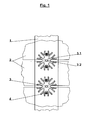
- zeigt die Verbindung mit Blickrichtung von oben. Die Bohlen sind dabei als durchsichtig angenommen und mit durchgehenden dünnen Linien symbolisiert dargestellt.
- Fig. 2: -
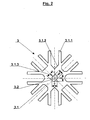
- zeigt den Distanzteil von Fig. 1 allein von oben in vergrößerter Darstellung.
- Fig. 3: -
- zeigt den Distanzteil von Fig. 1 im Schrägriss von oben in vergrößerter Darstellung.
- Fig. 4: -
- zeigt die Querschnittsfläche des Fortsatzes 3.2 des Distanzteils von Fig. 1 vergrößert. Durch die strichlierten Linien wird eine wesentliche Besonderheit der Querschnittsform hervorgehoben.
- Fig. 5: -
- zeigt eine zweite Ausführungsform eines Distanzteiles aus zwei voneinander lösbaren Teilen in einer Schrägrissansicht.
- Gemäß Fig. 1 bis Fig. 4 besteht der Distanzteil 3 aus einem ebenen Teil 3.1 und einem normal darauf nach oben ragenden Fortsatz 3.2.
- Der ebene Teil 3.1 bildet die Auflagefläche für die Bohlen 2 und liegt selbst auf der Unterkonstruktion 1 auf. Es ist sinnvoll, die Auflagefläche des ebenen Teiles 3.1 nicht einfach als Kreisfläche, Rechteck- oder regelmäßige Vieleckfläche auszubilden, sondern sie in mehrere eher schmale einseitig miteinander verbundene Arme 3.3 aufzuteilen, da damit das Trocknen erleichtert wird.
- Ein Fortsatz 3.2 des Distanzteils erstreckt sich so in den Spalt zwischen zwei benachbarten Bohlen 2, dass diese an seinen Flanken anliegen. Damit ist die Breite des Spaltes zwischen zwei benachbarten Bohlen 2 durch die in dieser Richtung liegende Breite des Fortsatzes 3.2, und damit durch die Lage des Fortsatzes 3.2 bestimmt.
- Für den - hier nicht dargestellten Fall - dass Form oder Lage des Fortsatzes 3.2 von der eines senkrecht von der Unterkonstruktion 1 empor stehenden Profils abweicht, sei klargestellt, dass mit der Formulierung "Breite des Fortsatzes" nicht die Breite einer bestimmten Querschnittsfläche des Fortsatzes gemeint ist, sondern die maximale Ausdehnung des gesamten Fortsatzes soweit er sich zwischen zwei benachbarten Bohlen befindet in der zu den einander zugewandeten Flankenflächen der beiden Bohlen 1 normal liegenden Richtung.
- Erfindungsgemäß ist diese Breite vom Drehwinkel des Distanzteils bei Drehung um eine normal zur Ebene der Unterkonstruktion 1 liegende Achse abhängig. In der hier dargestellten, vorteilhaften Ausführungsform ist der Fortsatz 3.2 ein senkrecht von der Unterkonstruktion 1 empor stehendes Profil mit der Querschnittsfläche eines geschlossenen, unregelmäßigen Polygonzugs, wobei einander gegenüberliegende Seiten zueinander parallel ausgerichtet sind. Je nachdem, mit welchem sich gegenüber liegenden Seitenpaar des Polygonzuges 3.2 der Distanzteil 3 an den Bohlen 2 anliegt, erhält man unterschiedliche Abstände der benachbarten Bohlen.
- Es ist vorteilhaft, die Querschnittsfläche dieses Fortsatzes mit parallelen gegenüberliegenden Seitenflächen so auszubilden, dass - wie in Fig. 4 veranschaulicht - Paare von zueinander parallel liegenden Seitenkanten der Querschnittsfläche bei Projektion in der zu ihrer Längsrichtung normal liegender Richtung aufeinander zu, einen überlappenden Längsbereich aufweisen. Dadurch wird erreicht, dass sich der Distanzteil nicht verdreht, wenn durch zwei benachbarte Bohlen von gegenüberliegenden Seiten auf den Fortsatz 3.2 gedrückt wird.
- Der Grundgedanke der Erfindung ließe sich auch verwirklichen, wenn der Fortsatz gänzlich anders, beispielsweise unregelmäßig klumpenartig geformt wäre, so lange seine Normalprojektion auf die Ebene der Unterkonstruktion keinen kreisförmigen Umfang hat.
- Es ist hilfreich, wenn einzelne Werte dieser richtungsabhängigen Breiten des Fortsatzes 3.2 durch Hinweise, welche um den Fortsatz 3.2 herum am ebenen Teil 3.1 angebracht sind, klar erkenntlich gemacht werden. Im dargestellten Beispiel sind diese Hinweise zum einen nach Art von technischen Zeichnungen gebildete Maßangaben 3.5, welche als Prägung am ebenen Teil 3.1 angebracht sind. Zum anderen liegen Hinweise in der Form der Einbuchtungen 3.1.2 zwischen benachbarten Armen 3.1.1 des ebenen Teils 3.1 des Distanzteils. Je nachdem wie viele verschiedene Richtungen zu Breiten des Fortsatzes 3.2 gekennzeichnet werden sollen, sind am ebenen Teil 3.1 verschiedene Formen von Einbuchtungen vorzusehen. Zum Einstellen eines bestimmten, immer gleichen Bohlenabstandes ist bei der Montage der Distanzteil 6 immer in gleicher Winkelausrichtung auf die Unterkonstruktion zu legen. Diese Winkelausrichtung kann beispielsweise eingestellt werden, indem jeweils jene Arme 3.1.1 des ebenen Teils 3.1 parallel zu den Bohlen 2 ausgerichtet werden, welche die spitz zusammenlaufend ausgebildete Einbuchtung 3.1.2 begrenzen.
- Idealerweise sind die Einbuchtungen 3.1.2 zumindest mit annähernd radial um den Fortsatz 3.2 verlaufender Tiefe und normal auf die Richtung von zu kennzeichnenden Breiten des Fortsatzes angeordnet. Damit wird es einfach möglich, bei der Montage mit den anzubringenden Befestigungsmitteln 4 - üblicherweise Schrauben oder Nägel -, durch die dann nicht sichtbaren Einbuchtungen zwischen zwei benachbarten, auf die Bohlenlängsrichtung normal stehenden Arme 3.1.1 hindurchzutreffen. Da sich die Breite des Fortsatzes 3.2 bei Drehung desselben um 180° wiederholt, ist es sinnvoll, auch die Formen der Einbuchtungen 3.1.2 bei Drehung des ebenen Teils 3.1 um 180° zu wiederholen. Es sollen also zwei gleichartige Einbuchtungen jeweils gegenüberliegend angeordnet werden. Das bedeutet, dass die Fläche des ebenen Teil 3.1 punktsymmetrisch und/oder entlang mehrerer Linien spiegelsymmetrisch ausgeführt sein sollte.
- Wenn der Fortsatz 3.2 als gerades Profil mit polygonaler Querschnittsfläche mit gegenüberliegend parallelen Seiten ausgebildet ist, sollte er dann so viele Seiten aufweisen, wie Einbuchtungen 3.1.2 am ebenen Teil angebracht sind.
- Es ist aber auch gut, den Fortsatz als gerades Profil mit polygonaler Querschnittsfläche auszubilden, wobei einer Seite jeweils eine Kante gegenüberliegt, sodass die Bohlen dann jeweils an einer Seite und an einer Kante anliegen. In diesem Fall sollte der Fortsatz halb so viele Seiten aufweisen, wie Einbuchtungen 3.1.2 am ebenen Teil angebracht sind.
- Es ist vorteilhaft, den Fortsatz 3.2 möglichst im Zentrum des ebenen Teils 3.1 anzubringen.
- Die einzelnen Holzteile einer Anordnung aus Bohlen und Unterkonstruktion quellen und schwinden in Abhängigkeit von der umgebenden Feuchtigkeit auch noch nach der Montage. Wenn benachbarte Bohlen an den zwischen ihnen angeordneten Fortsätzen 3.2 bzw. 13.2 anliegen, so führt das bei erhöhter Feuchtigkeit stattfindende Quellen der Bohlen zu erheblichen Spannungen in der gesamten Konstruktion. Das kann dazu führen, dass einzelne Befestigungselemente locker werden, und Bohlen je nach Witterung entweder angehoben werden oder wackeln. Derartige Schäden können zuverlässig vermieden werden, wenn zumindest bei jedem zweiten Spalt welcher zwischen zwei benachbarten Bohlen liegt, nach der Montage der Bohlen die Fortsätze der Distanzteile entfernt werden.
- Einen Distanzteil 13 in dafür vorteilhafte Bauweise zeigt Fig. 5. Der sich unter die Bohlen erstreckende ebene Teil 13.1 und der sich zwischen die Bohlen erstreckende Fortsatz 13.2 sind über eine Steckverbindung miteinander verbindbar bzw. voneinander lösbar. Bei geschlossener Verbindung zwischen diesen beiden Teilen steckt der als gerades Profil ausgebildete Fortsatz 13.2, dessen vertikale Länge größer ist als die Stärke der Bohlen, in eine Ausnehmung gleicher Querschnittsfläche des eben Teiles 13.1. Zur Montage der Bohlen sind ebener Teil 13.1 und Fortsatz 13.2 miteinander verbunden und es wird wie bei dem oben beschriebenen Distanzteil 3 vorgegangen. Nachdem zwei benachbarte Bohlen fixiert sind, werden die Fortsätze 13.2 entfernt indem sie herausgezogen werden. Im dargestellten Beispiel sind sie dafür an ihrem oberen Ende mit einem als Griffteil dienenden Ring versehen.
- Natürlich kann man die Lösbarkeit des Fortsatzes vom ebenen Teil auch anders, beispielsweise mit einer als dünner Querschnittsbereich ausgeführten Sollbruchstelle erreichen.
- Die beschriebenen und erwähnten Ausführungsformen bzw. Ausführungsvarianten des Distanzteils lassen sich einfach und kostengünstig als Kunststoffspritzgussteil fertigen.
Claims (10)
- Distanzteil zur Befestigung von Bohlen an einer Unterkonstruktion, welcher sich einerseits mit einem flächigen Teil zwischen Bohlen und Unterkonstruktion erstreckt, andererseits mit einem Fortsatz in den Spalt zwischen zwei benachbarten Bohlen erstreckt, dadurch gekennzeichnet, dass die Breite der Normalprojektion des zwischen benachbarten Bohlen (2) befindlichen Teils des Fortsatzes (3.2, 13:2) auf die Ebene der Unterkonstruktion (1) mit Änderung der Richtung in der die Breite innerhalb dieser Ebene gemessen wird, zwischen einem kleineren Minimalwert und einem größeren Maximalwert variiert.
- Distanzteil nach Anspruch 1, dadurch gekennzeichnet, dass die Querschnittsfläche des Fortsatzes (3.2, 13.2) zumindest über einen Teilbereich seiner Höhe konstant ist, dass der Fortsatz (3.2, 13.2) zumindest in diesem Teilbereich normal auf die Ebene der Unterkonstruktion (1) ausgerichtet ist, und dass die äußere Begrenzungslinie der Querschnittsfläche des Fortsatzes (3.2, 13.2) von der Kreisform abweicht.
- Distanzteil nach Anspruch 1 oder 2, dadurch gekennzeichnet, dass die Querschnittsform des Fortsatzes (3.2, 13.2) ein geschlossenes unregelmäßiges Vieleck ist.
- Distanzteil nach einem der bisherigen Ansprüche, dadurch gekennzeichnet, dass die Querschnittsfläche des Fortsatzes (3.2) gegenüberliegend zueinander parallel liegende Seitenkanten aufweist.
- Distanzteil nach Anspruch 4, dadurch gekennzeichnet, dass die paarweise zueinander parallel liegenden Seitenkanten bei Projektion in der zu ihrer Längsrichtung normal liegender Richtung aufeinander zu, einen überlappenden Längsbereich aufweisen.
- Distanzteil nach einem der bisherigen Ansprüche, dadurch gekennzeichnet, dass am ebenen Teil (3.1) um den Fortsatz (3.2) herum Kennzeichnungen für die jeweilige Breite des Fortsatzes (3.2) angebracht sind.
- Distanzteil nach Anspruch 6, dadurch gekennzeichnet, dass die Kennzeichnung eingeprägte Maßangaben (3.1.3) sind.
- Distanzteil nach Anspruch 7, dadurch gekennzeichnet, dass die Kennzeichnung durch die Form von Einbuchtungen (3.1.2) zwischen Armen (3.1.1) des flächigen Teils (3.1) gebildet ist.
- Distanzteil nach einem der bisherigen Ansprüche, dadurch gekennzeichnet, dass ebener Teil (13.1) und Fortsatz (13.2) lösbar miteinander verbunden sind.
- Distanzteil nach Anspruch 9, dadurch gekennzeichnet, dass die Höhe des Fortsatzes (13.2) größer ist als die Stärke der Bohlen (2).
Priority Applications (2)
| Application Number | Priority Date | Filing Date | Title |
|---|---|---|---|
| SI200730907T SI1918475T1 (sl) | 2006-10-25 | 2007-10-24 | Distanäśnik za pritrjevanje desk na podkonstrukcijo |
| PL07020800T PL1918475T3 (pl) | 2006-10-25 | 2007-10-24 | Element dystansowy służący do mocowania grubych desek na konstrukcji nośnej |
Applications Claiming Priority (2)
| Application Number | Priority Date | Filing Date | Title |
|---|---|---|---|
| AT17992006 | 2006-10-25 | ||
| AT0020807A AT504388B1 (de) | 2006-10-25 | 2007-02-09 | Distanzteil zur befestigung von bohlen an einer unterkonstruktion |
Publications (3)
| Publication Number | Publication Date |
|---|---|
| EP1918475A2 true EP1918475A2 (de) | 2008-05-07 |
| EP1918475A3 EP1918475A3 (de) | 2010-01-27 |
| EP1918475B1 EP1918475B1 (de) | 2012-02-08 |
Family
ID=38982595
Family Applications (1)
| Application Number | Title | Priority Date | Filing Date |
|---|---|---|---|
| EP07020800A Active EP1918475B1 (de) | 2006-10-25 | 2007-10-24 | Distanzteil zur Befestigung von Bohlen an einer Unterkonstruktion |
Country Status (5)
| Country | Link |
|---|---|
| EP (1) | EP1918475B1 (de) |
| AT (2) | AT504388B1 (de) |
| DK (1) | DK1918475T3 (de) |
| PL (1) | PL1918475T3 (de) |
| SI (1) | SI1918475T1 (de) |
Cited By (4)
| Publication number | Priority date | Publication date | Assignee | Title |
|---|---|---|---|---|
| DE202009005279U1 (de) * | 2009-09-15 | 2011-02-03 | Wolfcraft Gmbh | Bohr- bzw. Anreißlehre |
| EP3088629A1 (de) * | 2015-04-14 | 2016-11-02 | Protocas3D, S.L.U. | Verbesserte verschlussvorrichtung |
| GB2581209A (en) * | 2019-02-11 | 2020-08-12 | Ryno Ltd | Support system |
| US12091870B2 (en) | 2013-04-09 | 2024-09-17 | Acufloor, LLC | Device for leveling and aligning tiles and method for leveling and aligning tiles |
Families Citing this family (1)
| Publication number | Priority date | Publication date | Assignee | Title |
|---|---|---|---|---|
| KR102631824B1 (ko) * | 2022-05-03 | 2024-02-01 | 김기문 | 건축용 마감재 평탄화 기구 |
Citations (2)
| Publication number | Priority date | Publication date | Assignee | Title |
|---|---|---|---|---|
| DE2043633A1 (de) | 1969-09-06 | 1971-05-06 | Central Flooring Ltd , Chesterton, Newcastle, Stafford (Großbritannien) | Aus einer Vielzahl regelmäßiger Felder aufgebauter Fußboden |
| US6625951B1 (en) | 2001-12-10 | 2003-09-30 | Mccarthy Lawrence | Floor laying and leveling system |
Family Cites Families (5)
| Publication number | Priority date | Publication date | Assignee | Title |
|---|---|---|---|---|
| US4858399A (en) * | 1988-08-22 | 1989-08-22 | Salato Jr Peter A | Protective covering and spacer strip for a deck |
| US4955142A (en) * | 1989-09-06 | 1990-09-11 | Rieck Kenneth J | Deck spacing tool |
| DE29720122U1 (de) * | 1997-11-13 | 1999-03-18 | Gutjahr, Walter, 64404 Bickenbach | System zur Herstellung von Stelzen für Belagsaufbauten aus Platten auf Terrassen, Balkonen o.dgl. |
| DE202005013121U1 (de) * | 2005-08-19 | 2005-12-29 | Holzwerk Stumpp Gmbh & Co. Kg | Terrassenholz Distanz-/Montage- & Verlegehilfe |
| US7818923B2 (en) * | 2006-03-17 | 2010-10-26 | Alvarez David J | Tile spacer |
-
2007
- 2007-02-09 AT AT0020807A patent/AT504388B1/de active
- 2007-10-24 PL PL07020800T patent/PL1918475T3/pl unknown
- 2007-10-24 SI SI200730907T patent/SI1918475T1/sl unknown
- 2007-10-24 AT AT07020800T patent/ATE544922T1/de active
- 2007-10-24 DK DK07020800.4T patent/DK1918475T3/da active
- 2007-10-24 EP EP07020800A patent/EP1918475B1/de active Active
Patent Citations (2)
| Publication number | Priority date | Publication date | Assignee | Title |
|---|---|---|---|---|
| DE2043633A1 (de) | 1969-09-06 | 1971-05-06 | Central Flooring Ltd , Chesterton, Newcastle, Stafford (Großbritannien) | Aus einer Vielzahl regelmäßiger Felder aufgebauter Fußboden |
| US6625951B1 (en) | 2001-12-10 | 2003-09-30 | Mccarthy Lawrence | Floor laying and leveling system |
Cited By (12)
| Publication number | Priority date | Publication date | Assignee | Title |
|---|---|---|---|---|
| DE202009005279U1 (de) * | 2009-09-15 | 2011-02-03 | Wolfcraft Gmbh | Bohr- bzw. Anreißlehre |
| US12091870B2 (en) | 2013-04-09 | 2024-09-17 | Acufloor, LLC | Device for leveling and aligning tiles and method for leveling and aligning tiles |
| US12129670B2 (en) | 2013-04-09 | 2024-10-29 | Acufloor, LLC | Device for leveling and aligning tiles and method for leveling and aligning tiles |
| US12129671B2 (en) | 2013-04-09 | 2024-10-29 | Acufloor, LLC | Device for leveling and aligning tiles and method for leveling and aligning tiles |
| US12215507B2 (en) | 2013-04-09 | 2025-02-04 | Acufloor, LLC | Device for leveling and aligning tiles and method for leveling and aligning tiles |
| US12305408B2 (en) | 2013-04-09 | 2025-05-20 | Acufloor, L.L.C. | Device for leveling and aligning tiles and method for leveling and aligning tiles |
| US12398573B2 (en) | 2013-04-09 | 2025-08-26 | Acufloor, LLC | Device for leveling and aligning tiles and method for leveling and aligning tiles |
| US12546124B2 (en) | 2013-04-09 | 2026-02-10 | Acufloor, LLC | Device for leveling and aligning tiles and method for leveling and aligning tiles |
| US12559952B2 (en) | 2013-04-09 | 2026-02-24 | Acufloor, L.L.C. | Device for leveling and aligning tiles and method for leveling and aligning tiles |
| EP3088629A1 (de) * | 2015-04-14 | 2016-11-02 | Protocas3D, S.L.U. | Verbesserte verschlussvorrichtung |
| GB2581209A (en) * | 2019-02-11 | 2020-08-12 | Ryno Ltd | Support system |
| GB2581209B (en) * | 2019-02-11 | 2023-06-07 | Ryno Ltd | Support system |
Also Published As
| Publication number | Publication date |
|---|---|
| AT504388A1 (de) | 2008-05-15 |
| PL1918475T3 (pl) | 2012-07-31 |
| EP1918475B1 (de) | 2012-02-08 |
| ATE544922T1 (de) | 2012-02-15 |
| DK1918475T3 (da) | 2012-05-21 |
| EP1918475A3 (de) | 2010-01-27 |
| SI1918475T1 (sl) | 2012-09-28 |
| AT504388B1 (de) | 2008-07-15 |
Similar Documents
| Publication | Publication Date | Title |
|---|---|---|
| DE102009043465A1 (de) | Verlegehilfe | |
| EP2415946B1 (de) | Befestigung von Bohlen an einer Unterkonstruktion | |
| WO1990007066A2 (de) | Verbindungselement zum formschlüssigen verbinden | |
| AT504388B1 (de) | Distanzteil zur befestigung von bohlen an einer unterkonstruktion | |
| EP2754773B1 (de) | Unterkonstruktion für einen Bodenbelag | |
| DE4137814C2 (de) | Drehbarer Begrenzungsstein | |
| AT414029B (de) | Befestigung von bohlen an einer unterkonstruktion | |
| EP3382117B1 (de) | Höhenverstelleinrichtung für eine rinnenabdeckung | |
| CH678442A5 (de) | ||
| EP3078785B1 (de) | Befestigungsvorrichtung | |
| DE102015010894B4 (de) | Montagebausatz für den Terrassenbau | |
| EP3816366B1 (de) | Stützkonstruktion mit mehreren länglichen profilelementen | |
| DE20208282U1 (de) | Plattenlager | |
| EP3246488B1 (de) | Boden, insbesondere terrassen- oder balkonboden, und verwendung solches bodens | |
| DE102011120118B4 (de) | Beschlag | |
| DE102015208238A1 (de) | Randschalungselement mit einer Schalungsplatte zur Herstellung einer Betonplatte | |
| DE202005003011U1 (de) | Steher zum Einrichten von Zäunen und Geländern | |
| DE102020115155B4 (de) | Montagevorrichtung zur Erstellung eines Zaunelements für einen Sichtschutzzaun sowie Verfahren zur Montage eines Zaunelements für einen Sichtschutzzaun | |
| DE102010032068A1 (de) | Befestigungsklammer zur vorzugsweise unsichtbaren Befestigung von Profilbrettern | |
| EP4283060A1 (de) | Verlegekasten zur aufnahme einer ablaufgarnitur und lagerschiene | |
| EP2995743B1 (de) | Enddielenhaltevorrichtung für eine dielenanordnung | |
| DE102010015283A1 (de) | Fußbodensystem und Verbindungselement für ein Fußbodensystem | |
| DE102007024775B3 (de) | Befestigungssystem zum Verbinden von Holzbauteilen | |
| DE202023000600U1 (de) | Befestigungsmittel, Bewehrung und Abstandhalter | |
| DE102014005826B4 (de) | Vorrichtung und deren Verwendung |
Legal Events
| Date | Code | Title | Description |
|---|---|---|---|
| PUAI | Public reference made under article 153(3) epc to a published international application that has entered the european phase |
Free format text: ORIGINAL CODE: 0009012 |
|
| AK | Designated contracting states |
Kind code of ref document: A2 Designated state(s): AT BE BG CH CY CZ DE DK EE ES FI FR GB GR HU IE IS IT LI LT LU LV MC MT NL PL PT RO SE SI SK TR |
|
| AX | Request for extension of the european patent |
Extension state: AL BA HR MK RS |
|
| RAP1 | Party data changed (applicant data changed or rights of an application transferred) |
Owner name: SIMMER, JANE-BERYL |
|
| PUAL | Search report despatched |
Free format text: ORIGINAL CODE: 0009013 |
|
| AK | Designated contracting states |
Kind code of ref document: A3 Designated state(s): AT BE BG CH CY CZ DE DK EE ES FI FR GB GR HU IE IS IT LI LT LU LV MC MT NL PL PT RO SE SI SK TR |
|
| AX | Request for extension of the european patent |
Extension state: AL BA HR MK RS |
|
| RIC1 | Information provided on ipc code assigned before grant |
Ipc: E04F 15/04 20060101ALI20091221BHEP Ipc: E04F 21/00 20060101AFI20091221BHEP Ipc: E04B 5/12 20060101ALI20091221BHEP Ipc: E04F 15/02 20060101ALI20091221BHEP |
|
| AKX | Designation fees paid |
Designated state(s): AT BE BG CH CY CZ LI |
|
| REG | Reference to a national code |
Ref country code: DE Ref legal event code: 8566 |
|
| 17P | Request for examination filed |
Effective date: 20100726 |
|
| RBV | Designated contracting states (corrected) |
Designated state(s): AT BE BG CH CY CZ DE DK EE ES FI FR GB GR HU IE IS IT LI LT LU LV MC MT NL PL PT RO SE SI SK TR |
|
| 17Q | First examination report despatched |
Effective date: 20101117 |
|
| RAP1 | Party data changed (applicant data changed or rights of an application transferred) |
Owner name: SIMMER, JANE-BERYL |
|
| GRAP | Despatch of communication of intention to grant a patent |
Free format text: ORIGINAL CODE: EPIDOSNIGR1 |
|
| GRAS | Grant fee paid |
Free format text: ORIGINAL CODE: EPIDOSNIGR3 |
|
| GRAA | (expected) grant |
Free format text: ORIGINAL CODE: 0009210 |
|
| AK | Designated contracting states |
Kind code of ref document: B1 Designated state(s): AT BE BG CH CY CZ DE DK EE ES FI FR GB GR HU IE IS IT LI LT LU LV MC MT NL PL PT RO SE SI SK TR |
|
| REG | Reference to a national code |
Ref country code: GB Ref legal event code: FG4D Free format text: NOT ENGLISH |
|
| REG | Reference to a national code |
Ref country code: CH Ref legal event code: EP Ref country code: AT Ref legal event code: REF Ref document number: 544922 Country of ref document: AT Kind code of ref document: T Effective date: 20120215 |
|
| REG | Reference to a national code |
Ref country code: DE Ref legal event code: R096 Ref document number: 502007009236 Country of ref document: DE Effective date: 20120405 |
|
| REG | Reference to a national code |
Ref country code: NL Ref legal event code: T3 |
|
| REG | Reference to a national code |
Ref country code: DK Ref legal event code: T3 |
|
| REG | Reference to a national code |
Ref country code: SK Ref legal event code: T3 Ref document number: E 11585 Country of ref document: SK |
|
| LTIE | Lt: invalidation of european patent or patent extension |
Effective date: 20120208 |
|
| PG25 | Lapsed in a contracting state [announced via postgrant information from national office to epo] |
Ref country code: LT Free format text: LAPSE BECAUSE OF FAILURE TO SUBMIT A TRANSLATION OF THE DESCRIPTION OR TO PAY THE FEE WITHIN THE PRESCRIBED TIME-LIMIT Effective date: 20120208 Ref country code: IS Free format text: LAPSE BECAUSE OF FAILURE TO SUBMIT A TRANSLATION OF THE DESCRIPTION OR TO PAY THE FEE WITHIN THE PRESCRIBED TIME-LIMIT Effective date: 20120608 |
|
| REG | Reference to a national code |
Ref country code: PL Ref legal event code: T3 |
|
| REG | Reference to a national code |
Ref country code: IE Ref legal event code: FD4D |
|
| PG25 | Lapsed in a contracting state [announced via postgrant information from national office to epo] |
Ref country code: LV Free format text: LAPSE BECAUSE OF FAILURE TO SUBMIT A TRANSLATION OF THE DESCRIPTION OR TO PAY THE FEE WITHIN THE PRESCRIBED TIME-LIMIT Effective date: 20120208 Ref country code: PT Free format text: LAPSE BECAUSE OF FAILURE TO SUBMIT A TRANSLATION OF THE DESCRIPTION OR TO PAY THE FEE WITHIN THE PRESCRIBED TIME-LIMIT Effective date: 20120608 Ref country code: GR Free format text: LAPSE BECAUSE OF FAILURE TO SUBMIT A TRANSLATION OF THE DESCRIPTION OR TO PAY THE FEE WITHIN THE PRESCRIBED TIME-LIMIT Effective date: 20120509 Ref country code: FI Free format text: LAPSE BECAUSE OF FAILURE TO SUBMIT A TRANSLATION OF THE DESCRIPTION OR TO PAY THE FEE WITHIN THE PRESCRIBED TIME-LIMIT Effective date: 20120208 |
|
| PG25 | Lapsed in a contracting state [announced via postgrant information from national office to epo] |
Ref country code: CY Free format text: LAPSE BECAUSE OF FAILURE TO SUBMIT A TRANSLATION OF THE DESCRIPTION OR TO PAY THE FEE WITHIN THE PRESCRIBED TIME-LIMIT Effective date: 20120208 |
|
| PG25 | Lapsed in a contracting state [announced via postgrant information from national office to epo] |
Ref country code: EE Free format text: LAPSE BECAUSE OF FAILURE TO SUBMIT A TRANSLATION OF THE DESCRIPTION OR TO PAY THE FEE WITHIN THE PRESCRIBED TIME-LIMIT Effective date: 20120208 Ref country code: SE Free format text: LAPSE BECAUSE OF FAILURE TO SUBMIT A TRANSLATION OF THE DESCRIPTION OR TO PAY THE FEE WITHIN THE PRESCRIBED TIME-LIMIT Effective date: 20120208 Ref country code: RO Free format text: LAPSE BECAUSE OF FAILURE TO SUBMIT A TRANSLATION OF THE DESCRIPTION OR TO PAY THE FEE WITHIN THE PRESCRIBED TIME-LIMIT Effective date: 20120208 Ref country code: IE Free format text: LAPSE BECAUSE OF FAILURE TO SUBMIT A TRANSLATION OF THE DESCRIPTION OR TO PAY THE FEE WITHIN THE PRESCRIBED TIME-LIMIT Effective date: 20120208 |
|
| REG | Reference to a national code |
Ref country code: CH Ref legal event code: PUE Owner name: SIHGA HANDELS GMBH Free format text: SIMMER, JANE-BERYL#DAVIDWEG 5#4810 GMUNDEN (AT) -TRANSFER TO- SIHGA HANDELS GMBH#GEWERBEPARK KLEINREITH 4#4694 OHLSDORF (AT) |
|
| REG | Reference to a national code |
Ref country code: DE Ref legal event code: R097 Ref document number: 502007009236 Country of ref document: DE |
|
| PLBE | No opposition filed within time limit |
Free format text: ORIGINAL CODE: 0009261 |
|
| STAA | Information on the status of an ep patent application or granted ep patent |
Free format text: STATUS: NO OPPOSITION FILED WITHIN TIME LIMIT |
|
| REG | Reference to a national code |
Ref country code: FR Ref legal event code: TP Owner name: SIHGA HANDELS GMBH, AT Effective date: 20121212 |
|
| 26N | No opposition filed |
Effective date: 20121109 |
|
| REG | Reference to a national code |
Ref country code: DE Ref legal event code: R097 Ref document number: 502007009236 Country of ref document: DE Effective date: 20121109 |
|
| REG | Reference to a national code |
Ref country code: SI Ref legal event code: SP73 Owner name: SIHGA HANDELS GMBH; AT Effective date: 20130213 |
|
| PG25 | Lapsed in a contracting state [announced via postgrant information from national office to epo] |
Ref country code: ES Free format text: LAPSE BECAUSE OF FAILURE TO SUBMIT A TRANSLATION OF THE DESCRIPTION OR TO PAY THE FEE WITHIN THE PRESCRIBED TIME-LIMIT Effective date: 20120519 |
|
| PG25 | Lapsed in a contracting state [announced via postgrant information from national office to epo] |
Ref country code: MC Free format text: LAPSE BECAUSE OF NON-PAYMENT OF DUE FEES Effective date: 20121031 |
|
| GBPC | Gb: european patent ceased through non-payment of renewal fee |
Effective date: 20121024 |
|
| PG25 | Lapsed in a contracting state [announced via postgrant information from national office to epo] |
Ref country code: GB Free format text: LAPSE BECAUSE OF NON-PAYMENT OF DUE FEES Effective date: 20121024 Ref country code: BG Free format text: LAPSE BECAUSE OF FAILURE TO SUBMIT A TRANSLATION OF THE DESCRIPTION OR TO PAY THE FEE WITHIN THE PRESCRIBED TIME-LIMIT Effective date: 20120508 |
|
| PG25 | Lapsed in a contracting state [announced via postgrant information from national office to epo] |
Ref country code: MT Free format text: LAPSE BECAUSE OF FAILURE TO SUBMIT A TRANSLATION OF THE DESCRIPTION OR TO PAY THE FEE WITHIN THE PRESCRIBED TIME-LIMIT Effective date: 20120208 |
|
| REG | Reference to a national code |
Ref country code: AT Ref legal event code: MM01 Ref document number: 544922 Country of ref document: AT Kind code of ref document: T Effective date: 20121031 |
|
| PG25 | Lapsed in a contracting state [announced via postgrant information from national office to epo] |
Ref country code: AT Free format text: LAPSE BECAUSE OF NON-PAYMENT OF DUE FEES Effective date: 20121031 |
|
| PG25 | Lapsed in a contracting state [announced via postgrant information from national office to epo] |
Ref country code: TR Free format text: LAPSE BECAUSE OF FAILURE TO SUBMIT A TRANSLATION OF THE DESCRIPTION OR TO PAY THE FEE WITHIN THE PRESCRIBED TIME-LIMIT Effective date: 20120208 |
|
| PG25 | Lapsed in a contracting state [announced via postgrant information from national office to epo] |
Ref country code: HU Free format text: LAPSE BECAUSE OF FAILURE TO SUBMIT A TRANSLATION OF THE DESCRIPTION OR TO PAY THE FEE WITHIN THE PRESCRIBED TIME-LIMIT Effective date: 20071024 |
|
| REG | Reference to a national code |
Ref country code: FR Ref legal event code: PLFP Year of fee payment: 9 |
|
| REG | Reference to a national code |
Ref country code: FR Ref legal event code: PLFP Year of fee payment: 10 |
|
| REG | Reference to a national code |
Ref country code: FR Ref legal event code: PLFP Year of fee payment: 11 |
|
| PGFP | Annual fee paid to national office [announced via postgrant information from national office to epo] |
Ref country code: LU Payment date: 20171019 Year of fee payment: 11 |
|
| PGFP | Annual fee paid to national office [announced via postgrant information from national office to epo] |
Ref country code: CZ Payment date: 20171023 Year of fee payment: 11 Ref country code: DK Payment date: 20171019 Year of fee payment: 11 Ref country code: SK Payment date: 20171023 Year of fee payment: 11 |
|
| PGFP | Annual fee paid to national office [announced via postgrant information from national office to epo] |
Ref country code: BE Payment date: 20171019 Year of fee payment: 11 Ref country code: NL Payment date: 20171019 Year of fee payment: 11 Ref country code: SI Payment date: 20170925 Year of fee payment: 11 |
|
| REG | Reference to a national code |
Ref country code: FR Ref legal event code: PLFP Year of fee payment: 12 |
|
| PGFP | Annual fee paid to national office [announced via postgrant information from national office to epo] |
Ref country code: AT Payment date: 20181017 Year of fee payment: 10 |
|
| REG | Reference to a national code |
Ref country code: DK Ref legal event code: EBP Effective date: 20181031 |
|
| REG | Reference to a national code |
Ref country code: NL Ref legal event code: MM Effective date: 20181101 |
|
| REG | Reference to a national code |
Ref country code: BE Ref legal event code: MM Effective date: 20181031 |
|
| PG25 | Lapsed in a contracting state [announced via postgrant information from national office to epo] |
Ref country code: LU Free format text: LAPSE BECAUSE OF NON-PAYMENT OF DUE FEES Effective date: 20181024 |
|
| REG | Reference to a national code |
Ref country code: SK Ref legal event code: MM4A Ref document number: E 11585 Country of ref document: SK Effective date: 20181024 |
|
| PG25 | Lapsed in a contracting state [announced via postgrant information from national office to epo] |
Ref country code: CZ Free format text: LAPSE BECAUSE OF NON-PAYMENT OF DUE FEES Effective date: 20181024 Ref country code: NL Free format text: LAPSE BECAUSE OF NON-PAYMENT OF DUE FEES Effective date: 20181101 |
|
| PG25 | Lapsed in a contracting state [announced via postgrant information from national office to epo] |
Ref country code: SK Free format text: LAPSE BECAUSE OF NON-PAYMENT OF DUE FEES Effective date: 20181024 Ref country code: BE Free format text: LAPSE BECAUSE OF NON-PAYMENT OF DUE FEES Effective date: 20181031 Ref country code: SI Free format text: LAPSE BECAUSE OF NON-PAYMENT OF DUE FEES Effective date: 20181025 |
|
| REG | Reference to a national code |
Ref country code: SI Ref legal event code: KO00 Effective date: 20190701 |
|
| PG25 | Lapsed in a contracting state [announced via postgrant information from national office to epo] |
Ref country code: DK Free format text: LAPSE BECAUSE OF NON-PAYMENT OF DUE FEES Effective date: 20181031 |
|
| REG | Reference to a national code |
Ref country code: DE Ref legal event code: R119 Ref document number: 502007009236 Country of ref document: DE |
|
| REG | Reference to a national code |
Ref country code: CH Ref legal event code: PL |
|
| PG25 | Lapsed in a contracting state [announced via postgrant information from national office to epo] |
Ref country code: LI Free format text: LAPSE BECAUSE OF NON-PAYMENT OF DUE FEES Effective date: 20191031 Ref country code: CH Free format text: LAPSE BECAUSE OF NON-PAYMENT OF DUE FEES Effective date: 20191031 Ref country code: DE Free format text: LAPSE BECAUSE OF NON-PAYMENT OF DUE FEES Effective date: 20200501 |
|
| PGFP | Annual fee paid to national office [announced via postgrant information from national office to epo] |
Ref country code: IT Payment date: 20251024 Year of fee payment: 19 |
|
| PGFP | Annual fee paid to national office [announced via postgrant information from national office to epo] |
Ref country code: FR Payment date: 20251029 Year of fee payment: 19 |
|
| PGFP | Annual fee paid to national office [announced via postgrant information from national office to epo] |
Ref country code: PL Payment date: 20251016 Year of fee payment: 19 |