EP1918560A2 - Contrôle combiné pour fournir de l'air de refroidissement et de l'air de support dans une buse de moteur à turbine - Google Patents
Contrôle combiné pour fournir de l'air de refroidissement et de l'air de support dans une buse de moteur à turbine Download PDFInfo
- Publication number
- EP1918560A2 EP1918560A2 EP07254244A EP07254244A EP1918560A2 EP 1918560 A2 EP1918560 A2 EP 1918560A2 EP 07254244 A EP07254244 A EP 07254244A EP 07254244 A EP07254244 A EP 07254244A EP 1918560 A2 EP1918560 A2 EP 1918560A2
- Authority
- EP
- European Patent Office
- Prior art keywords
- nozzle
- air
- flow
- ring
- liner ring
- Prior art date
- Legal status (The legal status is an assumption and is not a legal conclusion. Google has not performed a legal analysis and makes no representation as to the accuracy of the status listed.)
- Granted
Links
Images




Classifications
-
- F—MECHANICAL ENGINEERING; LIGHTING; HEATING; WEAPONS; BLASTING
- F02—COMBUSTION ENGINES; HOT-GAS OR COMBUSTION-PRODUCT ENGINE PLANTS
- F02K—JET-PROPULSION PLANTS
- F02K1/00—Plants characterised by the form or arrangement of the jet pipe or nozzle; Jet pipes or nozzles peculiar thereto
- F02K1/78—Other construction of jet pipes
- F02K1/82—Jet pipe walls, e.g. liners
-
- F—MECHANICAL ENGINEERING; LIGHTING; HEATING; WEAPONS; BLASTING
- F02—COMBUSTION ENGINES; HOT-GAS OR COMBUSTION-PRODUCT ENGINE PLANTS
- F02K—JET-PROPULSION PLANTS
- F02K1/00—Plants characterised by the form or arrangement of the jet pipe or nozzle; Jet pipes or nozzles peculiar thereto
- F02K1/06—Varying effective area of jet pipe or nozzle
- F02K1/12—Varying effective area of jet pipe or nozzle by means of pivoted flaps
Definitions
- This application relates to a control for air pressure supplied to assist an actuator in balancing forces on a linkage for controlling a nozzle cross-sectional area in a gas turbine engine.
- a gas turbine engine includes a fan section, a compression section, a combustion section and a turbine section.
- An axis of the engine is centrally disposed along the engine and extends longitudinally through the sections.
- a primary flow path for working medium gases extends axially through the sections of the engine.
- the nozzle for the gas turbine engine is typically provided with an actuation structure that can cause a plurality of flaps to pivot radially inwardly or outwardly to control the size of the nozzle opening.
- a hydraulic actuator drives a synchronous ring (“sync ring”), which is connected through linkages to the plurality of flaps.
- a control causes the actuator to move the flaps between various positions to provide a desired cross-sectional area.
- a liner ring which controls the flow of cooling air to the interior of the nozzle.
- the liner ring is rotated between a blocking position and an open position dependent on whether cooling air is necessary. Under certain conditions, such as when an aircraft is hovering, less cooling air is necessary. By blocking the flow of cooling air to the nozzle, additional cooling air is available for other purposes.
- a liner ring as known in the art is rotated to control the flow of cooling air to the inner periphery of a nozzle in a gas turbine engine.
- the liner ring is rotated by a motor to a position such that openings in the liner ring are not aligned with openings in a housing structure leading into the nozzle. In this position, the flow of cooling air will be blocked, and cooling air is available for other purposes in the gas turbine engine.
- the liner ring is rotated to a position such that the openings in the liner ring align with the openings in the housing and cooling air is delivered to the inner periphery of the nozzle.
- the liner ring is also constrained to rotate with an outer ring.
- the outer ring is biased axially relative to the liner ring such that an end surface of the outer ring abuts a valve plate in the housing.
- the valve plate has openings leading to the rear surface of an actuation structure for the flap.
- a motor and control can rotate the liner ring and thus, the outer ring between positions selectively allowing or blocking flow to the rear of the sync ring.
- the additional feature of controlling the flow of air to the rear of the sync ring is achieved with the same motor which is already utilized to rotate the liner ring.
- Figure 1A shows a gas turbine engine 10.
- a fan section 11 moves air and rotates about an axial center line 12.
- a compressor section 13, a combustion section 14, and a turbine section 15 are also centered on the axial center line 12.
- a nozzle section 16 of the turbine discharges gas downstream.
- Figure 1A is a highly schematic view, however, it does show the main components of the gas turbine engine. Further, while a particular type of gas turbine engine is illustrated in this figure, it should be understood that the present invention extends to other types of gas turbine engines.
- a plurality of flaps 31 at the end of the nozzle 16 can be pivoted radially inwardly or outwardly to control the cross-sectional area at the nozzle.
- a hydraulic actuator 41 drives a sync ring 44 through a connection at 46.
- Air pressure within the nozzle 40 acts on an inner surface of the flaps 31, while an ambient pressure 42 outside the flaps 31 acts on an outer surface of the flaps 31.
- the air pressure at 40 is much greater than the ambient air pressure 42.
- This high pressure imbalance creates forces on the sync ring 44 and linkages.
- pressurized air is delivered through openings 48 to a rear surface of the sync ring 44 to assist in handling the load. In this prior art structure, there is no control of the flow of this air.
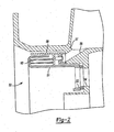
- Figure 2 shows a structure which supplements the Figure 1B actuation structure, and controls the flow of airflow into the rear surface of the sync ring 44.
- an assembly 50 includes a liner ring 51 having a plurality of openings 52 which can be selectively aligned with openings 54 to deliver cooling air into the inner periphery of the nozzle, and flaps 31.
- an outer ring 58 is positioned adjacent to the liner ring 51, and as will be explained, controls the flow of air flow through openings 56 to the rear surface of the sync ring 44 when less air flow is desired.
- a spring 60 biases the outer ring 58 against the openings 56 in a housing structure 57.
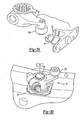
- Figure 3A shows details of the liner ring 51, and in particular a slot or track 68.
- An actuation structure 70 includes a bearing 172 which is to be received in the slot 68.
- the bearing 172 is associated with a drive having a spindle 76 driven by an actuator motor 78.
- a restrictor plate 74 seals off the mounting of the spindle in a fixed housing.
- a control for motor 78 receives feedback with regard to the condition of the engine, and can determine whether airflow is desired for cooling air at the inner periphery of the nozzle, and as actuation air to supplement the air acting on the sync ring.
- the control and motor 78 are shown schematically, however, it would preferably include a rotary motor, and a control for selectively driving the motor.
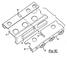
- Figure 3C shows features of the outer ring 58, and in particular a slot 64 which is associated with a lug 66 on the liner ring 51. While a single mating structure 64 and 66 is shown, there could be a plurality of such mating structures spaced around the periphery of the rings. Further, valve closures 62 extend forwardly from a forward face 63 of the outer ring 58. When the closures 62 are aligned with the openings 56 airflow is blocked. When the outer ring 58 is rotated, closures 62 are spaced from openings 56 such that the air can flow into the openings 56.
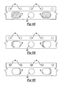
- Figure 4A shows a first position which may be considered a "hover" position for an associated aircraft. In this position, the temperature within the nozzle may not be as high as sometimes are experienced. As shown, the liner ring 51 has been rotated such that solid structure 70 is aligned with the openings 54. Now, cooling air will not be delivered to the interior of the nozzle. On the other hand, air can flow through openings 72, and around the outer ring 58, and reach the openings 56 in the housing 57. Figure 4B shows that the openings 54 are blocked while the openings 56 are open.
- Figure 5A shows another position, such as when an aircraft carrying the inventive gas turbine engine is under normal flying conditions.
- the liner ring 51 is rotated such that openings 52 are aligned with the openings 54, and cooling air is provided to the nozzle.
- the ring 58 is rotated to a position similar to that shown in Figure 4A such that air can also flow to the openings 56.
- Figure 5B shows that the openings 54 and 56 are both open.
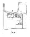
- Figure 6A shows yet another position, wherein reduced airflow to the rear of the sync ring is necessary. As mentioned, such a position would typically occur at low speed and low altitude flying.
- the outer ring 58 is rotated such that the closures 62 block the openings 56.
- the openings 54 are opened.
- the openings 56 are blocked while the openings 54 are opened.
- a designer would be able to selectively form structure on the two rings such that these three positions can be easily achieved by simply rotating the liner ring a particular amount.
Landscapes
- Engineering & Computer Science (AREA)
- Chemical & Material Sciences (AREA)
- Combustion & Propulsion (AREA)
- Mechanical Engineering (AREA)
- General Engineering & Computer Science (AREA)
- Turbine Rotor Nozzle Sealing (AREA)
- Control Of Turbines (AREA)
Applications Claiming Priority (1)
| Application Number | Priority Date | Filing Date | Title |
|---|---|---|---|
| US11/588,884 US7854124B2 (en) | 2006-10-27 | 2006-10-27 | Combined control for supplying cooling air and support air in a turbine engine nozzle |
Publications (3)
| Publication Number | Publication Date |
|---|---|
| EP1918560A2 true EP1918560A2 (fr) | 2008-05-07 |
| EP1918560A3 EP1918560A3 (fr) | 2011-06-15 |
| EP1918560B1 EP1918560B1 (fr) | 2013-02-13 |
Family
ID=38969846
Family Applications (1)
| Application Number | Title | Priority Date | Filing Date |
|---|---|---|---|
| EP07254244A Active EP1918560B1 (fr) | 2006-10-27 | 2007-10-26 | Contrôle combiné pour fournir de l'air de refroidissement et de l'air de support dans une buse de moteur à turbine |
Country Status (3)
| Country | Link |
|---|---|
| US (1) | US7854124B2 (fr) |
| EP (1) | EP1918560B1 (fr) |
| JP (1) | JP2008111434A (fr) |
Families Citing this family (11)
| Publication number | Priority date | Publication date | Assignee | Title |
|---|---|---|---|---|
| US8015996B2 (en) * | 2005-04-28 | 2011-09-13 | United Technologies Corporation | Gas turbine engine air valve assembly |
| US7845176B2 (en) * | 2007-03-20 | 2010-12-07 | United Technologies Corporation | Mode strut and divergent flap interface |
| US8235345B2 (en) | 2008-04-30 | 2012-08-07 | United Technologies Corp. | Gas turbine engine systems and related methods involving thermally isolated retention |
| FR2933128B1 (fr) * | 2008-06-25 | 2010-09-17 | Snecma | Dispositif de prelevement d'air de refroidissement dans une turbomachine |
| FR2933127B1 (fr) * | 2008-06-25 | 2015-04-24 | Snecma | Dispositif de prelevement d'air de refroidissement dans une turbomachine |
| FR2937679B1 (fr) * | 2008-10-24 | 2010-12-03 | Snecma | Dispositif de prelevement d'air de refroidissement dans une turbomachine |
| US9140213B2 (en) | 2011-12-06 | 2015-09-22 | United Technologies Corporation | Leaf spring damper for a turbine engine fuel delivery system |
| US9057455B2 (en) * | 2012-01-20 | 2015-06-16 | Hamilton Sundstrand Corporation | Crank |
| US9840984B2 (en) * | 2013-08-20 | 2017-12-12 | United Technologies Corporation | Linkage to control and restrain flap movement |
| PL421120A1 (pl) | 2017-04-04 | 2018-10-08 | General Electric Company Polska Spolka Z Ograniczona Odpowiedzialnoscia | Silnik turbinowy i części składowe do stosowania w nim |
| US11444507B2 (en) * | 2019-10-04 | 2022-09-13 | Hamilton Sundstrand Corporation | Actuation motor with cooling fins |
Family Cites Families (16)
| Publication number | Priority date | Publication date | Assignee | Title |
|---|---|---|---|---|
| US4447009A (en) * | 1981-12-28 | 1984-05-08 | United Technologies Corporation | Three-dimensional axially translatable convergent/divergent nozzle assembly |
| US4440346A (en) * | 1981-12-28 | 1984-04-03 | United Technologies Corporation | Axially translatable variable area convergent/divergent nozzle |
| US4440347A (en) * | 1981-12-28 | 1984-04-03 | United Technologies Corporation | Simplified means for balancing the loads on a variable area nozzle |
| US4420932A (en) * | 1982-03-02 | 1983-12-20 | The United States Of America As Represented By The Secretary Of The Air Force | Pressure control system for convergent-divergent exhaust nozzle |
| US5150839A (en) * | 1991-03-14 | 1992-09-29 | General Electric Company | Nozzle load management |
| US5209059A (en) * | 1991-12-27 | 1993-05-11 | The United States Of America As Represented By The Secretary Of The Air Force | Active cooling apparatus for afterburners |
| US5833139A (en) * | 1995-09-06 | 1998-11-10 | United Technologies Corporation | Single variable flap exhaust nozzle |
| US5813611A (en) | 1996-09-27 | 1998-09-29 | United Technologies Corporation | Compact pressure balanced fulcrum-link nozzle |
| US5794850A (en) * | 1996-09-27 | 1998-08-18 | United Technologies Corporation | Enclosed pressure balanced sync ring nozzle |
| US5797544A (en) * | 1996-09-27 | 1998-08-25 | United Technologies Corporation | C/D nozzle with synchronizing ring link suspension |
| US6021637A (en) * | 1997-09-29 | 2000-02-08 | General Electric Company | Integrated fluidic CD nozzle for gas turbine engine |
| US6418709B1 (en) * | 2000-05-15 | 2002-07-16 | United Technologies Corporation | Gas turbine engine liner |
| US6694723B2 (en) * | 2002-03-27 | 2004-02-24 | United Technologies Corporation | Valve assembly for gas turbine engine |
| US7225622B2 (en) | 2003-07-21 | 2007-06-05 | United Technologies Corporation | Turbine engine nozzle |
| FR2860045B1 (fr) * | 2003-09-24 | 2006-01-06 | Snecma Moteurs | Systeme de ventilation pour une tuyere d'ejection convergente divergente |
| US7581382B2 (en) * | 2005-04-28 | 2009-09-01 | United Technologies Corporation | Gas turbine engine air valve assembly |
-
2006
- 2006-10-27 US US11/588,884 patent/US7854124B2/en active Active
-
2007
- 2007-10-19 JP JP2007271939A patent/JP2008111434A/ja active Pending
- 2007-10-26 EP EP07254244A patent/EP1918560B1/fr active Active
Also Published As
| Publication number | Publication date |
|---|---|
| EP1918560A3 (fr) | 2011-06-15 |
| EP1918560B1 (fr) | 2013-02-13 |
| US20080098742A1 (en) | 2008-05-01 |
| US7854124B2 (en) | 2010-12-21 |
| JP2008111434A (ja) | 2008-05-15 |
Similar Documents
| Publication | Publication Date | Title |
|---|---|---|
| EP1918560B1 (fr) | Contrôle combiné pour fournir de l'air de refroidissement et de l'air de support dans une buse de moteur à turbine | |
| EP1472446B1 (fr) | Actionneur de vanne de demarreur de type turbine a air | |
| US12486811B2 (en) | Propeller assembly and pitch control unit | |
| US8863529B2 (en) | Variable pressure ratio compressor | |
| EP2066890B1 (fr) | Flux modulaire à travers un système de refroidissement de moteur à turbine à gaz | |
| US7066710B2 (en) | Pneumatic valve control having improved opening characteristics and an air turbine starter incorporating the same | |
| US20040000656A1 (en) | Dual actuator air turbine starter valve | |
| EP3626942B1 (fr) | Soupape de purge de stabilité de moteur à turbine à gaz avec arrêt passif et actif | |
| EP1870332B1 (fr) | Agencement bimoteur d'un rotor à réaction avec cheminement individuel du fluide de propulsion | |
| US6910851B2 (en) | Turbofan jet engine having a turbine case cooling valve | |
| EP1766488A2 (fr) | Commande de soupape pneumatique faisant appel a une retroaction de pression en aval et demarreur de turbine a air comprenant cette commande de soupape pneumatique | |
| EP2932068B1 (fr) | Moteur à turbine à gaz pourvu d'un système de refroidissement pour système d'engrenages d'entraînement et commande de pas | |
| EP1302640B1 (fr) | Propulseur additionnel avec cycle variable | |
| EP1908950B1 (fr) | Contrôle à équilibrage de pression pour tuyère de moteur de turbine à gaz | |
| EP3636896B1 (fr) | Ensemble d'organe de commande | |
| EP1722071B1 (fr) | Agencement de vanne pour une turbine à gaz et un procédé associé de reconfiguration d'un moteur | |
| US20250116338A1 (en) | Double bellows valve for preventing undesired valve failure positions | |
| EP3842627B1 (fr) | Soupape d'air de démarreur de turbine à air | |
| EP3992086B1 (fr) | Aéronef et son procédé de fonctionnement | |
| EP4438878B1 (fr) | Soupape de commande et démarreur de turbine à air combinés |
Legal Events
| Date | Code | Title | Description |
|---|---|---|---|
| PUAI | Public reference made under article 153(3) epc to a published international application that has entered the european phase |
Free format text: ORIGINAL CODE: 0009012 |
|
| AK | Designated contracting states |
Kind code of ref document: A2 Designated state(s): AT BE BG CH CY CZ DE DK EE ES FI FR GB GR HU IE IS IT LI LT LU LV MC MT NL PL PT RO SE SI SK TR |
|
| AX | Request for extension of the european patent |
Extension state: AL BA HR MK RS |
|
| PUAL | Search report despatched |
Free format text: ORIGINAL CODE: 0009013 |
|
| AK | Designated contracting states |
Kind code of ref document: A3 Designated state(s): AT BE BG CH CY CZ DE DK EE ES FI FR GB GR HU IE IS IT LI LT LU LV MC MT NL PL PT RO SE SI SK TR |
|
| AX | Request for extension of the european patent |
Extension state: AL BA HR MK RS |
|
| 17P | Request for examination filed |
Effective date: 20111215 |
|
| AKX | Designation fees paid |
Designated state(s): DE FR GB |
|
| GRAP | Despatch of communication of intention to grant a patent |
Free format text: ORIGINAL CODE: EPIDOSNIGR1 |
|
| GRAS | Grant fee paid |
Free format text: ORIGINAL CODE: EPIDOSNIGR3 |
|
| GRAA | (expected) grant |
Free format text: ORIGINAL CODE: 0009210 |
|
| AK | Designated contracting states |
Kind code of ref document: B1 Designated state(s): DE FR GB |
|
| REG | Reference to a national code |
Ref country code: GB Ref legal event code: FG4D |
|
| REG | Reference to a national code |
Ref country code: DE Ref legal event code: R096 Ref document number: 602007028392 Country of ref document: DE Effective date: 20130411 |
|
| PLBE | No opposition filed within time limit |
Free format text: ORIGINAL CODE: 0009261 |
|
| STAA | Information on the status of an ep patent application or granted ep patent |
Free format text: STATUS: NO OPPOSITION FILED WITHIN TIME LIMIT |
|
| 26N | No opposition filed |
Effective date: 20131114 |
|
| REG | Reference to a national code |
Ref country code: DE Ref legal event code: R097 Ref document number: 602007028392 Country of ref document: DE Effective date: 20131114 |
|
| REG | Reference to a national code |
Ref country code: FR Ref legal event code: ST Effective date: 20140630 |
|
| PG25 | Lapsed in a contracting state [announced via postgrant information from national office to epo] |
Ref country code: FR Free format text: LAPSE BECAUSE OF NON-PAYMENT OF DUE FEES Effective date: 20131031 |
|
| REG | Reference to a national code |
Ref country code: DE Ref legal event code: R082 Ref document number: 602007028392 Country of ref document: DE Representative=s name: SCHMITT-NILSON SCHRAUD WAIBEL WOHLFROM PATENTA, DE |
|
| REG | Reference to a national code |
Ref country code: DE Ref legal event code: R082 Ref document number: 602007028392 Country of ref document: DE Representative=s name: SCHMITT-NILSON SCHRAUD WAIBEL WOHLFROM PATENTA, DE Ref country code: DE Ref legal event code: R081 Ref document number: 602007028392 Country of ref document: DE Owner name: UNITED TECHNOLOGIES CORP. (N.D.GES.D. STAATES , US Free format text: FORMER OWNER: UNITED TECHNOLOGIES CORPORATION, EAST HARTFORD, CONN., US |
|
| REG | Reference to a national code |
Ref country code: DE Ref legal event code: R081 Ref document number: 602007028392 Country of ref document: DE Owner name: RAYTHEON TECHNOLOGIES CORPORATION (N.D.GES.D.S, US Free format text: FORMER OWNER: UNITED TECHNOLOGIES CORP. (N.D.GES.D. STAATES DELAWARE), FARMINGTON, CONN., US Ref country code: DE Ref legal event code: R081 Ref document number: 602007028392 Country of ref document: DE Owner name: RTX CORPORATION (N.D.GES.D. STAATES DELAWARE),, US Free format text: FORMER OWNER: UNITED TECHNOLOGIES CORP. (N.D.GES.D. STAATES DELAWARE), FARMINGTON, CONN., US |
|
| P01 | Opt-out of the competence of the unified patent court (upc) registered |
Effective date: 20230519 |
|
| PGFP | Annual fee paid to national office [announced via postgrant information from national office to epo] |
Ref country code: GB Payment date: 20250923 Year of fee payment: 19 |
|
| REG | Reference to a national code |
Ref country code: DE Ref legal event code: R081 Ref document number: 602007028392 Country of ref document: DE Owner name: RTX CORPORATION (N.D.GES.D. STAATES DELAWARE),, US Free format text: FORMER OWNER: RAYTHEON TECHNOLOGIES CORPORATION (N.D.GES.D.STAATES DELAWARE), ARLINGTON, VA, US |
|
| PGFP | Annual fee paid to national office [announced via postgrant information from national office to epo] |
Ref country code: DE Payment date: 20250923 Year of fee payment: 19 |