EP1918689A2 - Procédé et dispositif destinés au positionnement d'un échantillon dans un banc d'essai pour un bâti tournant de véhicules sur rails - Google Patents
Procédé et dispositif destinés au positionnement d'un échantillon dans un banc d'essai pour un bâti tournant de véhicules sur rails Download PDFInfo
- Publication number
- EP1918689A2 EP1918689A2 EP07019796A EP07019796A EP1918689A2 EP 1918689 A2 EP1918689 A2 EP 1918689A2 EP 07019796 A EP07019796 A EP 07019796A EP 07019796 A EP07019796 A EP 07019796A EP 1918689 A2 EP1918689 A2 EP 1918689A2
- Authority
- EP
- European Patent Office
- Prior art keywords
- carriage
- positioning
- bogie
- test
- measuring device
- Prior art date
- Legal status (The legal status is an assumption and is not a legal conclusion. Google has not performed a legal analysis and makes no representation as to the accuracy of the status listed.)
- Granted
Links
Images

Classifications
-
- G—PHYSICS
- G01—MEASURING; TESTING
- G01M—TESTING STATIC OR DYNAMIC BALANCE OF MACHINES OR STRUCTURES; TESTING OF STRUCTURES OR APPARATUS, NOT OTHERWISE PROVIDED FOR
- G01M17/00—Testing of vehicles
- G01M17/08—Railway vehicles
- G01M17/10—Suspensions, axles or wheels
Definitions
- the invention relates to a method for positioning a test piece in a test stand for bogies of rail vehicles according to the preamble of patent claim 1 and a device according to the preamble of patent claim 3.
- test stand for bogies and / or wheelsets of rail vehicles with two track sections is known, which form a continuous track and are arranged longitudinally behind one another.
- the test stand comprises a test table, wherein on the test table, a track section is arranged, which is movable relative to the other track section in at least two directions.
- a difficulty in the testing of bogies on the one hand, the exact and reproducible initiation and discharge of the test load, which is applied to the bogie.
- the other is It is crucial to position the bogie in the test bench so accurately that the test load is introduced symmetrically into the bogie and the power dissipation at the contact points of the wheels is defined and reproducible.
- the highly accurate and reproducible positioning of the bogie in the test bench is thus the basis and prerequisite for the accurate determination and documentation of data on the characteristics of a bogie.
- the invention has for its object to provide a method with which specimens are to be positioned as bogies in an automatically running test method with high accuracy and reproducible in a test facility for bogies, and to provide a device for such positioning.
- the position of the bogie measured after being introduced into the test bench as an actual position and recorded and automatically corrected if necessary in the desired position.
- the bogies are introduced and deployed with wheels and molded flanges each on a height adjustable Einfahrgleisvortechnisch in the test.
- the test stand has at least four positioning units and a loading device.
- the positioning units are arranged with arranged receiving prisms for the wheels to a predetermined nominal center distance, while the bogie is retracted on the wheel flanges of the wheels on the Einfahrgleisvortechnisch in the test.
- a distance sensor attached to the respective upper X-carriage which in turn is arranged on a Y-carriage of the positioning units, measures the Y position of each running wheel (3) relative to the position of the respective receiving prism as actual position, and one respectively on the Y axis.
- Carriage mounted measuring device measures the Y position of each positioning unit relative to the associated impeller of the bogie as an actual position.
- the measured data are processed and detected correction quantities for the exact Y position of the respective positioning unit relative to the respective impeller and stored as a target position. Then the bogie is raised on the Einfahrgleisvoriques and the respective positioning unit adjusted to a predetermined signal of the control unit exactly in the detected Y-position as a target position by motor. The bogie is then lowered over the Einfahrgleisvorides back into the receiving prisms.
- a measuring device on the respective upper X-carriage of the respective positioning unit measures the respective X position of the respective positioning unit with respect to a deviation of the position of the upper X-carriage from the position of a lower X-carriage of the positioning unit as the actual position.
- the central control unit detects and stores necessary correction values for the exact X position of the positioning units relative to the wheels of the bogie in the test bench as desired position on the basis of the measured data of the X position. Then, the respective positioning unit is adjusted to a predetermined signal of the control unit exactly in the detected X-position as a target position by motor.
- a predetermined Tolerance limit when a measuring device, the wheel contact forces are measured, which are applied by applying the bogie in the test with the loading device, a correction can be made in a simple manner.
- a deviation from a predetermined position is detected by the central control unit via the measuring device respectively attached to Z-lifting devices of the respective positioning units.
- the required thickness or thickness of a spacer for height adjustment of the suspension can be determined by the central control unit.
- the device for positioning a bogie in the test stand has a positioning unit for each wheel of the bogie, which comprises a receiving prism arranged on a carriage movable in the X and Y directions and an integrated measuring device for measuring the wheel contact force as well as measuring devices for distance measurement and distance measurement ,
- the positioning unit is arranged adjustable in the Z direction.
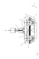
- a test bench 1 for a bogie 2 is shown in a schematic diagram.
- the bogie 2 has at least four wheels 3 with respective flange 5.
- the wheels 3 each rest on an associated X- / Y- / Z-positioning unit 6.
- a height adjustable Einfahrgleisvortechnisch 4 is shown for the bogie 2 in the test bed 1, which applies the load for the bogie.
- the loading device 7 simulates the weight of a locomotive body or a coach, the wheel contact forces resulting from the dead weight of the bogie 2 and the load by the loading device 7.
- a center distance a is specified.
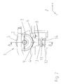
- FIG. 2 shows one of four positioning units 6 in a detail Z according to FIG.
- the bogie 2 to be tested with the respective impeller 3 is placed on the flange 5 to the approximate test position on the height adjustable Einfahrgleisvorraum.
- the four positioning units 6 are each equipped with a traversable via a dovetail guide Y-carriage 11 and lower X-slide 12 and with a height-adjustable Z-lifting device 14.
- a finely adjusting upper X-carriage 13 is also arranged via a dovetail guide, on each of which a receiving prism 9 with integrated measuring device 8 for determining the Radaufstandskraft and a distance sensor 10 are mounted.
- the four positioning units 6 with the receiving prism 9 are each preset to the nominal center distance a of the bogie 2 of mounted on the lower X-carriage 12 of the positioning units 6, not shown actuators. Then, the wheels 3 of the test piece or bogie 2 can be picked up by the receiving prisms 9 after lowering the runway track device 4.
- the servomotors, not shown, for positioning the lower X-carriages 12 of the positioning units 6 at the nominal center distance a receive predetermined signals from a central control unit (also not shown).
- the respective wheels 3 When lowering the bogie 2, the respective wheels 3 set centrally in the respective receiving prisms 9 and position the respective upper X-slide 13 by the weight of Bogie 2.
- the position of the upper X-carriage 13 relative to the position of the lower X-slide 12 is measured with displacement sensors of a measuring device 15 and given to the central control unit, not shown, for detecting the exact center distance as an actual position.
- the position of the respective impeller 3 relative to the position of the respective receiving prism 9 is detected as the actual position (FIG. 3).
- the acquired data is forwarded to the central control unit (not shown).
- the central control unit detects and optionally stores correction variables with regard to the deviation of the actual position from the predetermined exact Y position as desired position of the respective positioning unit 6 relative to the respective associated impeller 3. Furthermore, the central control unit supplies signals for adjusting the respective positioning unit 6 the desired position.
- the motor-driven Y-carriage 11 positions the positioning unit 6 with the receiving prism 9 exactly below the defined set-up point of each impeller 3 on the associated measuring circle diameter.
- a signal supplied by the central control unit, not shown which is caused due to a previously performed distance measurement with the distance sensor 10 and distance measurement with a mounted on the respective Y-slide 11 measuring device 15.
- the exact position of the recording prism 9 relative to the central center axis m is known.
- the process is carried out simultaneously on all four wheels 3 of the specimen or bogie 2.
- the motorized X-carriage 12 positions the positioning unit 6 in the predetermined coarse X-position as a target position on the test stand, again due to a predetermined signal of the central control unit, not shown. Then, after lowering the bogie 2 and centering in the pickup prisms 9, the X-layer is finely measured by the attached to the respective upper X-carriage 13 measuring device 15, as Actual position of the positioning unit 6 with respect to a deviation of the position of the upper X-carriage 13 from the position of the lower X-carriage 12.
- a correction variable in the central control unit not shown, for the exact X-position as a target position for the respective Positioning unit 6 detected relative to the respective impeller 3 of the bogie 2 and stored as a target position. The process is carried out simultaneously on all four wheels 3 of the specimen or bogie 2.
- the height adjustable Einfahrgleisvorraum 4 is briefly raised for the respective motorized adjustments of the positioning units 6 automatically controlled and lowered automatically controlled again after the adjustments made, so that the respective impeller 3 of the bogie 2 in the associated receiving prism 9 begins.
- the finely adjustable, mounted on the Y-carriage 11 upper X-carriage 13 is easily displaced in the X direction and centered when settling the test piece or bogie 2 in the receiving prism 9 in the installation position of the impeller 3 due to the given impeller diameter and the weight of the DUT.
- the displacement in the X-direction of the upper X-carriage 13 is measured by the attached to the respective upper X-carriage 13 associated measuring device 15 and added from the central control unit, not shown, to the approached position of the lower X-slide 12 of FIG. 2, 3 or subtracted.
- the bogie 2 is moved over the individual lower X-carriage 12 and Y-carriage 11 in the X and Y directions so that it is positioned not only with the fixed installation position exactly in the X and Y direction, but also by achtagens Moving the carriage in the Y direction is aligned exactly at right angles.
- the signals for the adjustment of the individual carriages are supplied by the control unit, not shown, which evaluates the detected data and in the required control pulses for not shown servomotors of the lower X-carriage 12 and the Y-carriage 11 converts.
- the bogie 2 to be tested is located after positioning and alignment in an aligned test position, which is clearly determined geometrically.
- the actual test steps such as the axle measurement and the test of the wheel contact force, are carried out after setting the exact test position.
- the bogie 2 is now aligned exactly at right angles and centrally in the test bench, so that incorrect measurements are excluded, which otherwise affect the accuracy and validity of the measurements carried out subsequently.
- the respective positioning unit 6 is arranged displaceably in the Z direction. Should a predetermined tolerance limit be exceeded during the test of the wheel contact force distribution, a deviation from the predetermined position is determined by the associated measuring device 15 mounted on the respective height-adjustable Z-lifting device 14. About a side dish simulation, the required thickness or thickness of a necessary spacer for height adjustment of the suspension is determined by the control unit, not shown.
- the measured data are fed to the central control unit, not shown, which detects correction quantities for the exact Y position of the respective positioning units 6 relative to the associated wheels 3 and stores them as desired position.
- the bogie 2 is raised via the entry track device 4.
- the respective positioning unit 6 is adjusted by motor in the precisely detected Y position to a signal supplied by the control unit, not shown.
- the X position of the respective positioning unit 6 with respect to a deviation of the position of the upper X-carriage 13 from the position of the lower X-carriage 12 is measured as an actual position by the attached to the respective upper X-carriage 13 associated measuring device 15.
- the measured data are fed to the control unit, not shown, detects and stores the correction values for the exact X position as a target position of the respective positioning device 6 for the respective impeller 3 of the bogie 2 in the test bench 1.
- the respective positioning unit 6 is adjusted in the detected X-position as a target position by a motor supplied to the control unit, not shown signal.
- the bogie 2 is now aligned exactly and prepared for the actual tests, for example, the determination of the wheel contact forces and the axis parallelism.
Landscapes
- Physics & Mathematics (AREA)
- General Physics & Mathematics (AREA)
- Length Measuring Devices With Unspecified Measuring Means (AREA)
- Control Of Conveyors (AREA)
- Train Traffic Observation, Control, And Security (AREA)
- Platform Screen Doors And Railroad Systems (AREA)
- Control Of Position Or Direction (AREA)
Applications Claiming Priority (1)
| Application Number | Priority Date | Filing Date | Title |
|---|---|---|---|
| DE102006051725A DE102006051725A1 (de) | 2006-10-30 | 2006-10-30 | Verfahren und Vorrichtung zum Positionieren eines Prüflings in einem Prüfstand für Drehgestelle von Schienenfahrzeugen |
Publications (3)
| Publication Number | Publication Date |
|---|---|
| EP1918689A2 true EP1918689A2 (fr) | 2008-05-07 |
| EP1918689A3 EP1918689A3 (fr) | 2008-09-17 |
| EP1918689B1 EP1918689B1 (fr) | 2010-04-14 |
Family
ID=38989688
Family Applications (1)
| Application Number | Title | Priority Date | Filing Date |
|---|---|---|---|
| EP07019796A Active EP1918689B1 (fr) | 2006-10-30 | 2007-10-10 | Procédé et dispositif destinés au positionnement d'un échantillon dans un banc d'essai pour un bâti tournant de véhicules sur rails |
Country Status (4)
| Country | Link |
|---|---|
| EP (1) | EP1918689B1 (fr) |
| AT (1) | ATE464552T1 (fr) |
| DE (2) | DE102006051725A1 (fr) |
| ES (1) | ES2341736T3 (fr) |
Cited By (9)
| Publication number | Priority date | Publication date | Assignee | Title |
|---|---|---|---|---|
| WO2010124686A3 (fr) * | 2009-04-27 | 2011-01-13 | AGG Anlagen- und Gerätebau GmbH | Procédé de contrôle de bogies et banc d'essai/de montage |
| WO2011057496A1 (fr) * | 2009-11-10 | 2011-05-19 | 青岛四方车辆研究所有限公司 | Banc d'essai intégré à la carrosserie d'un véhicule |
| CN103543023A (zh) * | 2013-11-02 | 2014-01-29 | 南车眉山车辆有限公司 | 转向架副构架可靠性试验装置 |
| CN104155124A (zh) * | 2014-08-14 | 2014-11-19 | 南车眉山车辆有限公司 | U形副构架刚度测试装置 |
| CN105258961A (zh) * | 2015-10-21 | 2016-01-20 | 重庆长征重工有限责任公司 | 轨道交通车辆转向架侧架极限垂直载荷试验装置 |
| CN106959216A (zh) * | 2017-05-24 | 2017-07-18 | 襄阳国铁机电股份有限公司 | 一种有轨电车转向架静载试验装置 |
| CN110274780A (zh) * | 2019-08-02 | 2019-09-24 | 吉林大学 | 一种平移式变轨距转向架变轨功能及可靠性试验台 |
| CN111912633A (zh) * | 2019-06-12 | 2020-11-10 | 中车大同电力机车有限公司 | 机车偏折测试方法、机车偏折测试装置 |
| WO2022135711A1 (fr) * | 2020-12-23 | 2022-06-30 | Nencki Ag | Banc d'essai pour l'essai de bogies de véhicules ferroviaires |
Families Citing this family (3)
| Publication number | Priority date | Publication date | Assignee | Title |
|---|---|---|---|---|
| DE102011100207B4 (de) | 2011-05-02 | 2014-08-21 | Schenck Process Gmbh | Verfahren zum Prüfen eines Drehgestells eines Schienenfahrzeugs sowie Prüfstand für ein Drehgestell eines Schienenfahrzeugs |
| ES2435506B1 (es) * | 2012-06-19 | 2014-11-12 | Patentes Talgo, S.L. | Conjunto, banco y procedimiento de calibración de ejes dinamométricos ferroviarios |
| TWI823236B (zh) * | 2022-01-25 | 2023-11-21 | 財團法人工業技術研究院 | 用於軌道車輛之轉向架測試台的測試裝置 |
Family Cites Families (14)
| Publication number | Priority date | Publication date | Assignee | Title |
|---|---|---|---|---|
| EP0228500B2 (fr) * | 1985-08-12 | 1994-12-28 | Wilhelm Hegenscheidt Gesellschaft mbH | Méthode et dispositif pour la mesure sans contact du profil d'une roue des roues d'ensembles de roues de voie ferrée |
| DE3604186A1 (de) * | 1986-02-10 | 1987-08-13 | Fraunhofer Ges Forschung | Verfahren und einrichtung zur pruefung von schienenfahrzeugraedern unter betriebsaehnlichen belastungsbedingungen |
| DE3676091D1 (de) * | 1986-06-28 | 1991-01-17 | Hegenscheidt Gmbh Wilhelm | Verfahren zum ermitteln der radialen lage eines durch reprofilierung herzustellenden neuprofils und einrichtung zur durchfuehrung des verfahrens. |
| DE3641424A1 (de) * | 1986-12-04 | 1988-06-09 | Bayerische Motoren Werke Ag | Verfahren und vorrichtung zum ausrichten von kraftfahrzeugen auf pruefskids |
| US4793047A (en) * | 1986-12-18 | 1988-12-27 | General Electric Company | Method of adjusting the distribution of locomotive axle loads |
| DE8713927U1 (de) * | 1987-10-16 | 1988-01-21 | Wilhelm Hegenscheidt Gmbh, 5140 Erkelenz | Einrichtung zur Erfassung von Zustandsdaten an einem rollenden Radsatz |
| DE3824575A1 (de) * | 1988-07-19 | 1990-01-25 | Delu Luftkissen | Anlage mit mindestens einem aus zwei parallelen schienen bestehenden gleis zum radsatz- bzw. fahrgestellwechsel |
| ES2068066B1 (es) * | 1992-02-07 | 1996-08-01 | Invastesa | Estacion para control de rodaduras ferroviarias. |
| GB2266123A (en) * | 1992-04-16 | 1993-10-20 | Keith Ebbrell | Dynamic monitoring apparatus for rail vehicle bearings |
| US5574233A (en) * | 1994-10-17 | 1996-11-12 | Amsted Industries Incorporated | Non-contact railway wheel test apparatus and method |
| JP3438453B2 (ja) * | 1996-01-12 | 2003-08-18 | 株式会社明電舎 | 鉄道車両用試験装置 |
| DE19924781A1 (de) * | 1999-05-29 | 2000-11-30 | Bbc Reaktor Gmbh | Verfahren zum zerstörungsfreien Prüfen von in Schienenfahrzeugen eingebauten Eisenbahnrädern |
| DE102004021488B4 (de) * | 2003-06-04 | 2006-06-01 | Windhoff Bahn- Und Anlagentechnik Gmbh | Prüfstand für Drehgestelle und/oder Radsätze von Schienenfahrzeugen |
| DE10336042C5 (de) * | 2003-08-01 | 2011-01-20 | Windhoff Bahn- Und Anlagentechnik Gmbh | Anordnung und Verfahren zum Prüfen von Rädern eines Schienenfahrzeugs |
-
2006
- 2006-10-30 DE DE102006051725A patent/DE102006051725A1/de not_active Withdrawn
-
2007
- 2007-10-10 AT AT07019796T patent/ATE464552T1/de active
- 2007-10-10 ES ES07019796T patent/ES2341736T3/es active Active
- 2007-10-10 EP EP07019796A patent/EP1918689B1/fr active Active
- 2007-10-10 DE DE502007003454T patent/DE502007003454D1/de active Active
Cited By (20)
| Publication number | Priority date | Publication date | Assignee | Title |
|---|---|---|---|---|
| AU2010243988B2 (en) * | 2009-04-27 | 2017-01-12 | Agg Anlagen- Und Geraetebau Gmbh | Test method for bogies as well as test stand and assembly stand |
| US8516881B2 (en) | 2009-04-27 | 2013-08-27 | Agg Anlagen- Und Geraetebau Gmbh | Test method for bogies as well as test stand and assembly stand |
| WO2010124686A3 (fr) * | 2009-04-27 | 2011-01-13 | AGG Anlagen- und Gerätebau GmbH | Procédé de contrôle de bogies et banc d'essai/de montage |
| RU2546913C2 (ru) * | 2009-04-27 | 2015-04-10 | АГГ Анлаген-унд Геретебау ГмбХ | Испытательный и монтажный стенд |
| WO2011057496A1 (fr) * | 2009-11-10 | 2011-05-19 | 青岛四方车辆研究所有限公司 | Banc d'essai intégré à la carrosserie d'un véhicule |
| US8230730B2 (en) | 2009-11-10 | 2012-07-31 | Qingdao Sifang Rolling Stock Research Institute Co., Ltd. | Comprehensive test bed for vehicle body |
| CN103543023A (zh) * | 2013-11-02 | 2014-01-29 | 南车眉山车辆有限公司 | 转向架副构架可靠性试验装置 |
| CN103543023B (zh) * | 2013-11-02 | 2015-08-12 | 南车眉山车辆有限公司 | 转向架副构架可靠性试验装置 |
| CN104155124A (zh) * | 2014-08-14 | 2014-11-19 | 南车眉山车辆有限公司 | U形副构架刚度测试装置 |
| CN104155124B (zh) * | 2014-08-14 | 2016-09-07 | 中车眉山车辆有限公司 | U形副构架刚度测试装置 |
| CN105258961A (zh) * | 2015-10-21 | 2016-01-20 | 重庆长征重工有限责任公司 | 轨道交通车辆转向架侧架极限垂直载荷试验装置 |
| CN105258961B (zh) * | 2015-10-21 | 2017-10-20 | 重庆长征重工有限责任公司 | 轨道交通车辆转向架侧架极限垂直载荷试验装置 |
| CN106959216A (zh) * | 2017-05-24 | 2017-07-18 | 襄阳国铁机电股份有限公司 | 一种有轨电车转向架静载试验装置 |
| CN111912633A (zh) * | 2019-06-12 | 2020-11-10 | 中车大同电力机车有限公司 | 机车偏折测试方法、机车偏折测试装置 |
| CN111912633B (zh) * | 2019-06-12 | 2022-01-25 | 中车大同电力机车有限公司 | 机车偏折测试方法、机车偏折测试装置 |
| CN110274780A (zh) * | 2019-08-02 | 2019-09-24 | 吉林大学 | 一种平移式变轨距转向架变轨功能及可靠性试验台 |
| CN110274780B (zh) * | 2019-08-02 | 2024-04-12 | 吉林大学 | 一种平移式变轨距转向架变轨功能及可靠性试验台 |
| WO2022135711A1 (fr) * | 2020-12-23 | 2022-06-30 | Nencki Ag | Banc d'essai pour l'essai de bogies de véhicules ferroviaires |
| WO2022136066A1 (fr) * | 2020-12-23 | 2022-06-30 | Nencki Ag | Porte-moyeu pour porter une roue montée sur un bogie, et banc d'essai pour tester des bogies de véhicules ferroviaires |
| US12510440B2 (en) | 2020-12-23 | 2025-12-30 | Nencki Ag | Wheel carrier for supporting a wheel arranged on a bogie and test stand for testing bogies of railway vehicles |
Also Published As
| Publication number | Publication date |
|---|---|
| DE102006051725A1 (de) | 2008-05-08 |
| EP1918689A3 (fr) | 2008-09-17 |
| ATE464552T1 (de) | 2010-04-15 |
| ES2341736T3 (es) | 2010-06-25 |
| DE502007003454D1 (de) | 2010-05-27 |
| EP1918689B1 (fr) | 2010-04-14 |
Similar Documents
| Publication | Publication Date | Title |
|---|---|---|
| EP1918689B1 (fr) | Procédé et dispositif destinés au positionnement d'un échantillon dans un banc d'essai pour un bâti tournant de véhicules sur rails | |
| EP2386455B1 (fr) | Dispositif de contrôle de rails | |
| DE102004021488B4 (de) | Prüfstand für Drehgestelle und/oder Radsätze von Schienenfahrzeugen | |
| EP2276659B1 (fr) | Système de mesure de charges dans le contact roue-rail de véhicules ferroviaires | |
| DE102014006192A1 (de) | ,,Radsatzfreihebe-. -dreh- und -meßvorrichtung für Radsätze von Schienenfahrzeugen" | |
| EP3365652B1 (fr) | Dispositif et procédé d'étalonnage et/ou de réglage de dispositifs de mesure de forces dynamiques | |
| EP2216441A2 (fr) | Système de nivèlement pour ingénierie de bande | |
| DE19943744A1 (de) | Verfahren und Vorrichtung zur Radsatzprüfung | |
| EP2705344B1 (fr) | Procédé pour l'inspection d'un bogie d'un véhicule ferroviaire et banc d'essai pour un bogie de véhicule ferroviaire | |
| AT502214B1 (de) | Verfahren und vorrichtung zur erfassung der entgleisungsgefahr von schienenfahrzeugen | |
| DE69305899T2 (de) | Vorrichtung zur automatischen Bestimmung der Restspannung in einer Felge eines Radsatzes für Schienen, bzw. Gleisfahrzeuge | |
| EP1610103B1 (fr) | Procédé pour déterminer des poids de référence au moyen d'une balance dynamique pour wagons. | |
| DE3715460C1 (en) | Wind tunnel balance and method for operating it | |
| DE10336042B4 (de) | Anordnung und Verfahren zum Prüfen von Rädern eines Schienenfahrzeugs | |
| EP3182088B1 (fr) | Procédé de contrôle de fonctionnement de plaques flottantes faisant partie intégrante d'un banc d'essai de véhicule | |
| EP1582429A1 (fr) | Procédé de contrôle et d'évaluation d'un géométrie de dépassement des composants de voie ferrée | |
| EP1612551B1 (fr) | Procédé d'évaluation de la rugosité de rails et/out de segments de rail | |
| EP1170420A3 (fr) | Dispositif de mesure de la position d'une voie en cours de pose de voies ferrées et procédé de mise en oeuvre d'une telle mesure | |
| DE10009708C1 (de) | Verfahren und Vorrichtung zum Ermitteln der Eigenschaften der Drehdämpfung eines Drehgestells von Schienenfahrzeugen | |
| EP4558373B1 (fr) | Commande de la hauteur d'un train de roulement au moyen d'un capteur d'embarquement de passagers | |
| DE102009058190A1 (de) | Verfahren und Vorrichtung zur Profilierung einer Überlaufgeometrie von Gleisbauteilen | |
| DE2430202A1 (de) | Vorrichtung zur bestimmung der zulaessigen streckenhoechstgeschwindigkeit | |
| DE102006007948B3 (de) | Verfahren und Vorrichtung zur Messung der Profiltiefe von Reifen | |
| DE102010004501B4 (de) | Verfahren zur Bestimmung des Reibwertes auf der Basis der Erfassung von im schienengebundenen Fahrbetrieb auftretenden Kräften | |
| DE3513316C2 (fr) |
Legal Events
| Date | Code | Title | Description |
|---|---|---|---|
| PUAI | Public reference made under article 153(3) epc to a published international application that has entered the european phase |
Free format text: ORIGINAL CODE: 0009012 |
|
| AK | Designated contracting states |
Kind code of ref document: A2 Designated state(s): AT BE BG CH CY CZ DE DK EE ES FI FR GB GR HU IE IS IT LI LT LU LV MC MT NL PL PT RO SE SI SK TR |
|
| AX | Request for extension of the european patent |
Extension state: AL BA HR MK RS |
|
| RIN1 | Information on inventor provided before grant (corrected) |
Inventor name: MATICH, WALTER Inventor name: EHMKE, FRITZ |
|
| PUAL | Search report despatched |
Free format text: ORIGINAL CODE: 0009013 |
|
| AK | Designated contracting states |
Kind code of ref document: A3 Designated state(s): AT BE BG CH CY CZ DE DK EE ES FI FR GB GR HU IE IS IT LI LT LU LV MC MT NL PL PT RO SE SI SK TR |
|
| AX | Request for extension of the european patent |
Extension state: AL BA HR MK RS |
|
| 17P | Request for examination filed |
Effective date: 20090312 |
|
| 17Q | First examination report despatched |
Effective date: 20090415 |
|
| AKX | Designation fees paid |
Designated state(s): AT BE BG CH CY CZ DE DK EE ES FI FR GB GR HU IE IS IT LI LT LU LV MC MT NL PL PT RO SE SI SK TR |
|
| GRAP | Despatch of communication of intention to grant a patent |
Free format text: ORIGINAL CODE: EPIDOSNIGR1 |
|
| GRAS | Grant fee paid |
Free format text: ORIGINAL CODE: EPIDOSNIGR3 |
|
| GRAA | (expected) grant |
Free format text: ORIGINAL CODE: 0009210 |
|
| AK | Designated contracting states |
Kind code of ref document: B1 Designated state(s): AT BE BG CH CY CZ DE DK EE ES FI FR GB GR HU IE IS IT LI LT LU LV MC MT NL PL PT RO SE SI SK TR |
|
| REG | Reference to a national code |
Ref country code: GB Ref legal event code: FG4D Free format text: NOT ENGLISH |
|
| REG | Reference to a national code |
Ref country code: CH Ref legal event code: EP |
|
| REG | Reference to a national code |
Ref country code: IE Ref legal event code: FG4D Free format text: LANGUAGE OF EP DOCUMENT: GERMAN |
|
| REF | Corresponds to: |
Ref document number: 502007003454 Country of ref document: DE Date of ref document: 20100527 Kind code of ref document: P |
|
| REG | Reference to a national code |
Ref country code: SE Ref legal event code: TRGR |
|
| REG | Reference to a national code |
Ref country code: ES Ref legal event code: FG2A Ref document number: 2341736 Country of ref document: ES Kind code of ref document: T3 |
|
| REG | Reference to a national code |
Ref country code: NL Ref legal event code: VDEP Effective date: 20100414 |
|
| LTIE | Lt: invalidation of european patent or patent extension |
Effective date: 20100414 |
|
| PG25 | Lapsed in a contracting state [announced via postgrant information from national office to epo] |
Ref country code: NL Free format text: LAPSE BECAUSE OF FAILURE TO SUBMIT A TRANSLATION OF THE DESCRIPTION OR TO PAY THE FEE WITHIN THE PRESCRIBED TIME-LIMIT Effective date: 20100414 Ref country code: LT Free format text: LAPSE BECAUSE OF FAILURE TO SUBMIT A TRANSLATION OF THE DESCRIPTION OR TO PAY THE FEE WITHIN THE PRESCRIBED TIME-LIMIT Effective date: 20100414 |
|
| REG | Reference to a national code |
Ref country code: IE Ref legal event code: FD4D |
|
| PG25 | Lapsed in a contracting state [announced via postgrant information from national office to epo] |
Ref country code: LV Free format text: LAPSE BECAUSE OF FAILURE TO SUBMIT A TRANSLATION OF THE DESCRIPTION OR TO PAY THE FEE WITHIN THE PRESCRIBED TIME-LIMIT Effective date: 20100414 Ref country code: SI Free format text: LAPSE BECAUSE OF FAILURE TO SUBMIT A TRANSLATION OF THE DESCRIPTION OR TO PAY THE FEE WITHIN THE PRESCRIBED TIME-LIMIT Effective date: 20100414 Ref country code: IS Free format text: LAPSE BECAUSE OF FAILURE TO SUBMIT A TRANSLATION OF THE DESCRIPTION OR TO PAY THE FEE WITHIN THE PRESCRIBED TIME-LIMIT Effective date: 20100814 |
|
| PG25 | Lapsed in a contracting state [announced via postgrant information from national office to epo] |
Ref country code: CY Free format text: LAPSE BECAUSE OF FAILURE TO SUBMIT A TRANSLATION OF THE DESCRIPTION OR TO PAY THE FEE WITHIN THE PRESCRIBED TIME-LIMIT Effective date: 20100526 Ref country code: PL Free format text: LAPSE BECAUSE OF FAILURE TO SUBMIT A TRANSLATION OF THE DESCRIPTION OR TO PAY THE FEE WITHIN THE PRESCRIBED TIME-LIMIT Effective date: 20100414 |
|
| PG25 | Lapsed in a contracting state [announced via postgrant information from national office to epo] |
Ref country code: PT Free format text: LAPSE BECAUSE OF FAILURE TO SUBMIT A TRANSLATION OF THE DESCRIPTION OR TO PAY THE FEE WITHIN THE PRESCRIBED TIME-LIMIT Effective date: 20100816 Ref country code: EE Free format text: LAPSE BECAUSE OF FAILURE TO SUBMIT A TRANSLATION OF THE DESCRIPTION OR TO PAY THE FEE WITHIN THE PRESCRIBED TIME-LIMIT Effective date: 20100414 Ref country code: DK Free format text: LAPSE BECAUSE OF FAILURE TO SUBMIT A TRANSLATION OF THE DESCRIPTION OR TO PAY THE FEE WITHIN THE PRESCRIBED TIME-LIMIT Effective date: 20100414 Ref country code: GR Free format text: LAPSE BECAUSE OF FAILURE TO SUBMIT A TRANSLATION OF THE DESCRIPTION OR TO PAY THE FEE WITHIN THE PRESCRIBED TIME-LIMIT Effective date: 20100715 Ref country code: IE Free format text: LAPSE BECAUSE OF FAILURE TO SUBMIT A TRANSLATION OF THE DESCRIPTION OR TO PAY THE FEE WITHIN THE PRESCRIBED TIME-LIMIT Effective date: 20100414 |
|
| PLBE | No opposition filed within time limit |
Free format text: ORIGINAL CODE: 0009261 |
|
| STAA | Information on the status of an ep patent application or granted ep patent |
Free format text: STATUS: NO OPPOSITION FILED WITHIN TIME LIMIT |
|
| PG25 | Lapsed in a contracting state [announced via postgrant information from national office to epo] |
Ref country code: CZ Free format text: LAPSE BECAUSE OF FAILURE TO SUBMIT A TRANSLATION OF THE DESCRIPTION OR TO PAY THE FEE WITHIN THE PRESCRIBED TIME-LIMIT Effective date: 20100414 Ref country code: SK Free format text: LAPSE BECAUSE OF FAILURE TO SUBMIT A TRANSLATION OF THE DESCRIPTION OR TO PAY THE FEE WITHIN THE PRESCRIBED TIME-LIMIT Effective date: 20100414 Ref country code: RO Free format text: LAPSE BECAUSE OF FAILURE TO SUBMIT A TRANSLATION OF THE DESCRIPTION OR TO PAY THE FEE WITHIN THE PRESCRIBED TIME-LIMIT Effective date: 20100414 |
|
| 26N | No opposition filed |
Effective date: 20110117 |
|
| BERE | Be: lapsed |
Owner name: SCHENCK PROCESS G.M.B.H. Effective date: 20101031 |
|
| PG25 | Lapsed in a contracting state [announced via postgrant information from national office to epo] |
Ref country code: MC Free format text: LAPSE BECAUSE OF NON-PAYMENT OF DUE FEES Effective date: 20101031 |
|
| PG25 | Lapsed in a contracting state [announced via postgrant information from national office to epo] |
Ref country code: BE Free format text: LAPSE BECAUSE OF NON-PAYMENT OF DUE FEES Effective date: 20101031 |
|
| PG25 | Lapsed in a contracting state [announced via postgrant information from national office to epo] |
Ref country code: MT Free format text: LAPSE BECAUSE OF FAILURE TO SUBMIT A TRANSLATION OF THE DESCRIPTION OR TO PAY THE FEE WITHIN THE PRESCRIBED TIME-LIMIT Effective date: 20100414 Ref country code: IT Free format text: LAPSE BECAUSE OF NON-PAYMENT OF DUE FEES Effective date: 20101010 |
|
| PG25 | Lapsed in a contracting state [announced via postgrant information from national office to epo] |
Ref country code: HU Free format text: LAPSE BECAUSE OF FAILURE TO SUBMIT A TRANSLATION OF THE DESCRIPTION OR TO PAY THE FEE WITHIN THE PRESCRIBED TIME-LIMIT Effective date: 20101015 Ref country code: LU Free format text: LAPSE BECAUSE OF NON-PAYMENT OF DUE FEES Effective date: 20101010 Ref country code: BG Free format text: LAPSE BECAUSE OF FAILURE TO SUBMIT A TRANSLATION OF THE DESCRIPTION OR TO PAY THE FEE WITHIN THE PRESCRIBED TIME-LIMIT Effective date: 20100414 |
|
| PG25 | Lapsed in a contracting state [announced via postgrant information from national office to epo] |
Ref country code: TR Free format text: LAPSE BECAUSE OF FAILURE TO SUBMIT A TRANSLATION OF THE DESCRIPTION OR TO PAY THE FEE WITHIN THE PRESCRIBED TIME-LIMIT Effective date: 20100414 |
|
| PG25 | Lapsed in a contracting state [announced via postgrant information from national office to epo] |
Ref country code: BG Free format text: LAPSE BECAUSE OF FAILURE TO SUBMIT A TRANSLATION OF THE DESCRIPTION OR TO PAY THE FEE WITHIN THE PRESCRIBED TIME-LIMIT Effective date: 20100714 |
|
| REG | Reference to a national code |
Ref country code: FR Ref legal event code: PLFP Year of fee payment: 9 |
|
| REG | Reference to a national code |
Ref country code: FR Ref legal event code: PLFP Year of fee payment: 10 |
|
| REG | Reference to a national code |
Ref country code: DE Ref legal event code: R082 Ref document number: 502007003454 Country of ref document: DE Ref country code: DE Ref legal event code: R081 Ref document number: 502007003454 Country of ref document: DE Owner name: SCHENCK PROCESS EUROPE GMBH, DE Free format text: FORMER OWNER: SCHENCK PROCESS GMBH, 64293 DARMSTADT, DE |
|
| REG | Reference to a national code |
Ref country code: FR Ref legal event code: PLFP Year of fee payment: 11 |
|
| REG | Reference to a national code |
Ref country code: FR Ref legal event code: PLFP Year of fee payment: 12 |
|
| REG | Reference to a national code |
Ref country code: CH Ref legal event code: PFA Owner name: SCHENCK PROCESS EUROPE GMBH, DE Free format text: FORMER OWNER: SCHENCK PROCESS GMBH, DE |
|
| REG | Reference to a national code |
Ref country code: GB Ref legal event code: 732E Free format text: REGISTERED BETWEEN 20181115 AND 20181130 |
|
| REG | Reference to a national code |
Ref country code: ES Ref legal event code: PC2A Owner name: SCHENCK PROCESS EUROPE GMBH Effective date: 20181219 |
|
| REG | Reference to a national code |
Ref country code: DE Ref legal event code: R081 Ref document number: 502007003454 Country of ref document: DE Owner name: SCHENCK PROCESS EUROPE GMBH, DE Free format text: FORMER OWNER: SCHENCK PROCESS EUROPE GMBH, 64293 DARMSTADT, DE |
|
| REG | Reference to a national code |
Ref country code: AT Ref legal event code: PC Ref document number: 464552 Country of ref document: AT Kind code of ref document: T Owner name: SCHENCK PROCESS EUROPE GMBH, DE Effective date: 20190304 |
|
| PGFP | Annual fee paid to national office [announced via postgrant information from national office to epo] |
Ref country code: FI Payment date: 20201022 Year of fee payment: 14 Ref country code: SE Payment date: 20201028 Year of fee payment: 14 |
|
| REG | Reference to a national code |
Ref country code: FI Ref legal event code: MAE |
|
| REG | Reference to a national code |
Ref country code: SE Ref legal event code: EUG |
|
| PG25 | Lapsed in a contracting state [announced via postgrant information from national office to epo] |
Ref country code: SE Free format text: LAPSE BECAUSE OF NON-PAYMENT OF DUE FEES Effective date: 20211011 |
|
| PG25 | Lapsed in a contracting state [announced via postgrant information from national office to epo] |
Ref country code: FI Free format text: LAPSE BECAUSE OF NON-PAYMENT OF DUE FEES Effective date: 20211010 |
|
| REG | Reference to a national code |
Ref country code: DE Ref legal event code: R081 Ref document number: 502007003454 Country of ref document: DE Owner name: QLAR EUROPE GMBH, DE Free format text: FORMER OWNER: SCHENCK PROCESS EUROPE GMBH, 64293 DARMSTADT, DE |
|
| REG | Reference to a national code |
Ref country code: AT Ref legal event code: HC Ref document number: 464552 Country of ref document: AT Kind code of ref document: T Owner name: QLAR EUROPE GMBH, DE Effective date: 20250407 |
|
| REG | Reference to a national code |
Ref country code: CH Ref legal event code: U11 Free format text: ST27 STATUS EVENT CODE: U-0-0-U10-U11 (AS PROVIDED BY THE NATIONAL OFFICE) Effective date: 20251101 |
|
| REG | Reference to a national code |
Ref country code: ES Ref legal event code: PC2A Owner name: QLAR EUROPE GMBH Effective date: 20251105 |
|
| PGFP | Annual fee paid to national office [announced via postgrant information from national office to epo] |
Ref country code: DE Payment date: 20251021 Year of fee payment: 19 |
|
| PGFP | Annual fee paid to national office [announced via postgrant information from national office to epo] |
Ref country code: GB Payment date: 20251022 Year of fee payment: 19 |
|
| PGFP | Annual fee paid to national office [announced via postgrant information from national office to epo] |
Ref country code: AT Payment date: 20251022 Year of fee payment: 19 |
|
| PGFP | Annual fee paid to national office [announced via postgrant information from national office to epo] |
Ref country code: IT Payment date: 20251022 Year of fee payment: 19 |
|
| PGFP | Annual fee paid to national office [announced via postgrant information from national office to epo] |
Ref country code: FR Payment date: 20251029 Year of fee payment: 19 |
|
| PGFP | Annual fee paid to national office [announced via postgrant information from national office to epo] |
Ref country code: CH Payment date: 20251101 Year of fee payment: 19 |
|
| PGFP | Annual fee paid to national office [announced via postgrant information from national office to epo] |
Ref country code: ES Payment date: 20251210 Year of fee payment: 19 |