EP1919745B1 - Scheibenwischvorrichtung - Google Patents
Scheibenwischvorrichtung Download PDFInfo
- Publication number
- EP1919745B1 EP1919745B1 EP06764272A EP06764272A EP1919745B1 EP 1919745 B1 EP1919745 B1 EP 1919745B1 EP 06764272 A EP06764272 A EP 06764272A EP 06764272 A EP06764272 A EP 06764272A EP 1919745 B1 EP1919745 B1 EP 1919745B1
- Authority
- EP
- European Patent Office
- Prior art keywords
- sleeve
- wiper device
- windscreen wiper
- wiper
- spring
- Prior art date
- Legal status (The legal status is an assumption and is not a legal conclusion. Google has not performed a legal analysis and makes no representation as to the accuracy of the status listed.)
- Not-in-force
Links
- 239000000463 material Substances 0.000 claims description 5
- 208000027418 Wounds and injury Diseases 0.000 description 3
- 230000006378 damage Effects 0.000 description 3
- 208000014674 injury Diseases 0.000 description 3
- 238000005452 bending Methods 0.000 description 2
- 238000006073 displacement reaction Methods 0.000 description 2
- 238000000465 moulding Methods 0.000 description 2
- 238000010068 moulding (rubber) Methods 0.000 description 2
- 244000089486 Phragmites australis subsp australis Species 0.000 description 1
- 239000000956 alloy Substances 0.000 description 1
- 229910045601 alloy Inorganic materials 0.000 description 1
- 230000015572 biosynthetic process Effects 0.000 description 1
- 238000010276 construction Methods 0.000 description 1
- 238000002788 crimping Methods 0.000 description 1
- 238000004512 die casting Methods 0.000 description 1
- 238000009434 installation Methods 0.000 description 1
- 238000004519 manufacturing process Methods 0.000 description 1
- 239000000203 mixture Substances 0.000 description 1
- 239000007921 spray Substances 0.000 description 1
Images


Classifications
-
- B—PERFORMING OPERATIONS; TRANSPORTING
- B60—VEHICLES IN GENERAL
- B60S—SERVICING, CLEANING, REPAIRING, SUPPORTING, LIFTING, OR MANOEUVRING OF VEHICLES, NOT OTHERWISE PROVIDED FOR
- B60S1/00—Cleaning of vehicles
- B60S1/02—Cleaning windscreens, windows or optical devices
- B60S1/04—Wipers or the like, e.g. scrapers
- B60S1/0488—Wiper arrangement for crash protection or impact absorption
-
- B—PERFORMING OPERATIONS; TRANSPORTING
- B60—VEHICLES IN GENERAL
- B60S—SERVICING, CLEANING, REPAIRING, SUPPORTING, LIFTING, OR MANOEUVRING OF VEHICLES, NOT OTHERWISE PROVIDED FOR
- B60S1/00—Cleaning of vehicles
- B60S1/02—Cleaning windscreens, windows or optical devices
- B60S1/04—Wipers or the like, e.g. scrapers
- B60S1/32—Wipers or the like, e.g. scrapers characterised by constructional features of wiper blade arms or blades
- B60S1/34—Wiper arms; Mountings therefor
- B60S1/3488—Means for mounting wiper arms onto the vehicle
- B60S1/3493—Means for mounting the wiper shaft in the wiper bearing
-
- Y—GENERAL TAGGING OF NEW TECHNOLOGICAL DEVELOPMENTS; GENERAL TAGGING OF CROSS-SECTIONAL TECHNOLOGIES SPANNING OVER SEVERAL SECTIONS OF THE IPC; TECHNICAL SUBJECTS COVERED BY FORMER USPC CROSS-REFERENCE ART COLLECTIONS [XRACs] AND DIGESTS
- Y10—TECHNICAL SUBJECTS COVERED BY FORMER USPC
- Y10S—TECHNICAL SUBJECTS COVERED BY FORMER USPC CROSS-REFERENCE ART COLLECTIONS [XRACs] AND DIGESTS
- Y10S403/00—Joints and connections
- Y10S403/03—Load-responsive release
Definitions
- the invention relates to a windshield wiper device, in particular for a motor vehicle, with at least one wiper shaft.
- the vehicle must not protrude any parts that pose a risk of injury to pedestrians. For this reason, there are windshield wiper devices with predetermined breaking points, so that the windshield wiper device escapes from the danger zone on impact of a pedestrian.
- the predetermined breaking points are provided in the region of a connection between a wiper bearing and a vehicle body.
- the disadvantage here is that the predetermined breaking points are in the main load range of the wiper bearing, whereby the predetermined breaking points are also claimed during the wiper operation.
- the strength and rigidity of the predetermined breaking points depend not only on their geometric shape but also on the material properties and the manufacturing process.
- the alloy composition and the spray parameters due to the formation of voids and the like cause a considerable variation of the strength and stiffness values.
- the breaking point already fails during the wiper operation, whereby the windscreen wiper device fails.
- the predetermined breaking point fails.
- EP 0 916 559 A2 discloses a windshield wiper device for a motor vehicle with a wiper shaft, which is accommodated in a sleeve.
- the sleeve is fixedly received in a forming tube, whereas the wiper shaft relative to the sleeve is displaceable in the axial direction, if acting on the shaft, an axial force which exceeds a release force.
- On the inner wall of the sleeve are radially inwardly directed elevations, which protrude into recesses in the lateral surface of the wiper shaft and thereby lock the wiper shaft both in the direction of rotation and in the axial direction.
- the EP 1103 434 A1 shows a windshield wiper device with a wiper shaft in a molded part, wherein the wiper shaft is displaceable under the action of an axial force and locked in the molding using a spring washer, which is located on the end face of the molding and the lateral surface of the wiper shaft subjected to a holding force.
- the invention has the object to improve a windshield wiper device of the type mentioned in that the high demands on the pedestrian impact protection are met, and at the same time the trouble-free operation of the windscreen wiper device is ensured.
- the invention solves this problem with a windshield wiper device of the type mentioned, in which according to the invention the at least one wiper shaft is displaceable under the action of a force.
- the wiper shaft Upon impact of a pedestrian on the windshield wiper device, the wiper shaft deviates from the impact force, so that the windshield wiper device poses no risk of injury to the pedestrian.
- the windshield wiper device meets the high demands on pedestrian impact protection. Because a predetermined breaking point is dispensed with in the windscreen wiper device, a trouble-free wiping operation is possible while at the same time fulfilling the requirements for pedestrian impact protection.
- the at least one wiper shaft can be locked in the axial direction. As a result, a displacement of the wiper shaft in the axial direction during the wiping operation is excluded. Only when an impact on the wiper shaft, the lock is released, so that the wiper shaft can be moved in the axial direction of the danger area.
- the at least one wiper shaft can be stuck in a sleeve which is axially displaceable and lockable relative to a forming tube.
- a sleeve which is axially displaceable and lockable relative to a forming tube.
- a locking device may have a recess in the sleeve, in which engages a locking element. In this way, the release force can be set exactly to a certain value, when it reaches the lock solved and die.Wischerwelle is moved.
- Another way to set the release force exactly to a certain value is that the locking element is pressed with a spring element in the recess. The bias of the spring element then determines the release force.
- the release force depends on the shape of the locking element.
- the locking element may be a ball, an ellipsoid or a wedge.
- the spring element is designed as a spiral spring, as a rubber molding, as a bending beam spring or the like, then sufficiently high pressure forces can be generated on a very limited installation space. These types of springs thus ensure that the wiper shaft operates smoothly during the wiping operation, without being moved axially.
- the spring element and the locking element may be integrally formed. As a result, the assembly of the spring element and the locking element is simplified.
- the spring element and the locking element are a stamped and bent part, they can be produced inexpensively in large quantities.
- the locking can be provided in the region of a retaining eye attached to the forming tube and / or Krimpzapfens. Then no additional space for the lock is needed.
- the lock can be secured against rotation about its own axis.
- the sleeve can be secured against rotation about its own axis when the sleeve has at least one longitudinal wedge.
- the sleeve and / or the forming tube may be made of a die-cast material. Die casting materials have a high Zeitformstabiltician so that they ensure trouble-free operation throughout the life of the windshield wiper device.
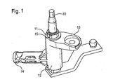
- FIGS. 1 and 2 show a wiper shaft 10 which is inserted in a sleeve 11.
- the sleeve 11 is inserted in a forming tube 12.
- a holding eye 13 is arranged, with which the forming tube 12 can be mounted on a body not shown here.
- a crimping pin 14 is arranged on the forming tube 12, which can be inserted into a likewise not shown circuit board tube.
- the sleeve 11 is displaceable relative to the forming tube 12 in the axial direction together with the wiper shaft 10.
- the wiper shaft 10 is provided with a retaining ring 20 and a washer 21 arranged underneath (see FIG Fig. 2 ) In the axial direction fixedly connected to the sleeve 11.
- the wiper shaft 10 and the sleeve 11 always perform axial displacements together.
- the sleeve 11 has a longitudinal wedge 15 (see Fig. 1 ), which secures the sleeve 11 against rotation about its own axis.
- An arresting device 22 has a recess in the sleeve into which a locking element 23 engages.
- the locking element 23 is pressed by a spring 24 in the recess.
- the locking element 23 is designed as a hemisphere and the spring 24 as a coil spring.
- the locking device 22 is provided in the region of the retaining eye 13, whereby the locking device 22 is accommodated in a space-saving manner.
- Fig. 3 shows a locking device 30, in which a locking element 31 is wedge-shaped.
- the release force is higher than in the hemispherical locking element 23 (see Fig. 2 ).
- Fig. 4 shows a locking device 40, in which a spring 41 is designed as a bending beam spring. With her relatively high pressure forces can be generated in a small space, so that 41 high release forces are achieved by the spring.
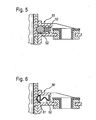
- a locking element 52 can then advantageously be designed as a ball.
- a locking member 61 and a spring element 62 are integrally formed. Due to the one-piece design, the assembly of the locking element 61 and the spring element 62 is simplified.
- the locking member 61 and the spring member 62 are made as a stamped and bent part, whereby they can be produced inexpensively in large quantities.
Landscapes
- Engineering & Computer Science (AREA)
- Mechanical Engineering (AREA)
- Vibration Dampers (AREA)
- Body Structure For Vehicles (AREA)
Abstract
Description
- Die Erfindung betrifft eine Scheibenwischvorrichtung, insbesondere für ein Kraftfahrzeug, mit mindestens einer Wischerwelle.
- An Scheibenwischvorrichtungen werden heutzutage hohe Anforderungen bezüglich des Fußgängeraufprallschutzes gestellt. Am Fahrzeug dürfen keine Teile herausragen, die für Fußgänger ein Verletzungsrisiko darstellen. Aus diesem Grund gibt es Scheibenwischvorrichtungen mit Sollbruchstellen, so dass die Scheibenwischvorrichtung beim Aufprall eines Fußgängers aus dem Gefahrenbereich ausweicht. Die Sollbruchstellen sind im Bereich einer Anbindung zwischen einem Wischerlager und einer Fahrzeugkarosserie vorgesehen. Nachteilig hierbei ist jedoch, dass die Sollbruchstellen im Hauptlastbereich des Wischerlagers liegen, wodurch die Sollbruchstellen auch während des Wischerbetriebes beansprucht werden. Die Festigkeit und die Steifigkeit der Sollbruchstellen hängen außer von ihrer geometrischen Gestalt auch von den Werkstoffeigenschaften und dem Herstellungsprozess ab. So bedingen beispielsweise die Legierungszusammensetzung und die Spritzparameter durch die Bildung von Lunkern und dergleichen eine erhebliche Streuung der Festigkeits- und Steifigkeitswerte. Somit besteht eine nicht zu vernachlässigende Gefahr, dass die Sollbruchstelle bereits während des Wischerbetriebes versagt, wodurch die Scheibenwischvorrichtung ausfällt. Außerdem kann im Falle eines Fußgängeraufpralls nicht gewährleistet werden, dass die Sollbruchstelle versagt.
- In der
EP 0 916 559 A2 ist eine Scheibenwischvorrichtung für ein Kraftfahrzeug mit einer Wischerwelle offenbart, welche in einer Hülse aufgenommen ist. Die Hülse ist in einem Formrohr fest aufgenommen, wohingegen die Wischerwelle gegenüber der Hülse in Achsrichtung verschiebbar ist, falls auf die Welle eine axiale Kraft wirkt, die eine Auslösekraft übersteigt. An der Innenwand der Hülse befinden sich radial nach innen weisende Erhebungen, die in Vertiefungen in der Mantelfläche der Wischerwelle einragen und dadurch die Wischerwelle sowohl in Drehrichtung als auch in Achsrichtung arretieren. Sobald die axiale Kraft auf die Wischerwelle die Auslösekraft übersteigt, gelangen die Erhebungen in Außereingriff mit den Vertiefungen, bis sich in Achsrichtung erstreckende Nuten in der Mantelfläche der Wischerwelle erreicht werden. Die Auslösekraft wird vom Material und der Geometrie der Erhebungen in Verbindung mit der Vertiefung bestimmt. DieEP 1103 434 A1 zeigt eine Scheibenwischvorrichtung mit einer Wischerwelle in einem Formteil, wobei die Wischerwelle unter der Einwirkung einer Axialkraft verschiebbar und im Formteil mithilfe einer Federscheibe arretiert ist, die sich an der Stirnseite des Formteils befindet und die Mantelfläche der Wischerwelle mit einer Haltekraft beaufschlagt. - Die Erfindung hat die Aufgabe, eine Scheibenwischvorrichtung der eingangs genannten Art dahingehend zu verbessern, dass die hohen Anforderungen an den Fußgängeraufprallschutz erfüllt werden, und gleichzeitig auch der störungsfreie Betrieb der Scheibenwischvorrichtung sichergestellt ist.
- Die Erfindung löst die gestellte Aufgabe mit einer Scheibenwischvorrichtung der eingangs genannten Art, bei der erfindungsgemäß die mindestens eine Wischerwelle bei Einwirkung einer Kraft verschiebbar ist. Beim Aufprall eines Fußgängers auf die Scheibenwischvorrichtung weicht die Wischerwelle der Aufprallkraft aus, so dass die Scheibenwischvorrichtung keine Verletzungsgefahr für den Fußgänger darstellt. Somit erfüllt die Scheibenwischvorrichtung die hohen Anforderungen an den Fußgängeraufprallschutz. Weil bei der Scheibenwischvorrichtung auf eine Sollbruchstelle verzichtet wird, ist ein störungsfreier Wischbetrieb bei gleichzeitiger Erfüllung der Anforderungen an den Fußgängeraufprallschutz möglich.
- Die mindestens eine Wischerwelle kann in axialer Richtung arretiert werden. Dadurch ist eine Verschiebung der Wischerwelle in axialer Richtung während des Wischbetriebes ausgeschlossen. Erst bei einem Aufprall auf die Wischerwelle wird die Arretierung gelöst, so dass die Wischerwelle in axialer Richtung aus dem Gefahrenbereich verschoben werden kann.
- In einer bevorzugten Ausführungsform kann die mindestens eine Wischerwelle in einer Hülse stecken, die relativ zu einem Formrohr axial verschiebbar und arretierbar ist. Dies ist ei-ne relativ einfache Konstruktion, mit der die erfindungsgemäßen Merkmale kostengünstig realisiert werden können. Wenn die Wischerwelle in axialer Richtung ortsfest mit der Hülse verbunden ist, dann können die Wischerwelle und die Hülse bei einem Aufprall gemeinsam aus dem Gefahrenbereich verschoben werden, wobei sich dann die Wischerwelle und die Hülse relativ zum Formrohr bewegen.
- Eine Arretiereinrichtung kann eine Vertiefung in der Hülse aufweisen, in welche ein Arretierelement eingreift. Auf diese Weise kann die Auslösekraft exakt auf einen bestimmten Wert eingestellt werden, bei dessen Erreichen die Arretierung gelöst und die.Wischerwelle verschoben wird.
- Eine weitere-Möglichkeit, um die Auslösekraft exakt auf einen bestimmten Wert einzustellen ist, dass das Arretierelement mit einem Federelement in die Vertiefung gedrückt wird. Die Vorspannung des Federelements bestimmt dann die Auslösekraft.
- Ferner ist die Auslösekraft von der Form des Arretierelements abhängig. Je nach-der gewünschten Höhe der Auslösekraft, kann das Arretierelement eine Kugel, ein Ellipsoid oder ein Keil sein.
- Wenn das Federelement als Spiralfeder, als Gummiformteil, als Biegebalkenfeder oder dergleichen ausgebildet ist, dann können auf einem stark begrenzten Einbauraum ausreichend hohe Druckkräfte erzeugt werden. Diese Federarten gewährleisten somit, dass die Wischerwelle während des Wischbetriebes störungsfrei arbeitet, ohne axial verschoben zu werden.
- Das Federelement und das Arretierelement können einstückig ausgebildet sein. Dadurch wird die Montage des Federelements und des Arretierelements vereinfacht.
- Wenn das Federelement und das Arretierelement ein Stanzbiegeteil sind, können sie kostengünstig in großen Stückzahlen hergestellt werden.
- Die Arretierung kann im Bereich eines am Formrohr angebrachten Halteauges und/oder Krimpzapfens vorgesehen sein. Dann wird kein zusätzlicher Bauraum für die Arretierung benötigt.
- Damit die Arretiereinrichtung nicht durch eine unbeabsichtigte Drehung der Hülse die Arretierung frei gibt, kann die Hülse gegen eine Drehung um ihre eigene Achse gesichert sein.
- Sehr einfach und somit kostengünstig kann die Hülse gegen eine Drehung um ihre eigene Achse gesichert werden, wenn die Hülse mindestens einen Längskeil aufweist.
- Die Hülse und/oder das Formrohr kann aus einem Druckgussmaterial gefertigt sein. Druckgussmaterialien weisen eine hohe Zeitformstabilität auf, so dass sie eine störungsfreie Funktion während der kompletten Lebensdauer der Scheibenwischvorrichtung gewährleisten.
- Nachfolgend wird ein Ausführungsbeispiel anhand der beiliegenden Zeichnungen näher erläutert.
- Im Einzelnen zeigen:
- Fig. 1
- eine perspektivische Ansicht auf ein Form- rohr mit einer Wischerwelle;
- Fig. 2
- eine Schnittansicht auf das Formrohr und die Wischerwelle aus
Fig. 1 mit einer ersten Ausführungsform einer Arretiereinrichtung; - Fig. 3
- eine Schnittansicht auf eine zweite Ausfüh- rungsform der Arretiereinrichtung;
- Fig. 4
- eine Schnittansicht auf eine dritte Ausfüh- rungsform der Arretiereinrichtung;
- Fig. 5
- eine Schnittansicht auf eine vierte Ausfüh- rungsform der Arretiereinrichtung;
- Fig. 6
- eine Schnittansicht auf eine fünfte Ausfüh- rungsform der Arretiereinrichtung.
- Die
Figuren 1 und2 zeigen eine Wischerwelle 10, die in einer Hülse 11 gesteckt. Die Hülse 11 steckt in einem Formrohr 12. An dem Formrohr 12 ist ein Halteauge 13 angeordnet, mit dem das Formrohr 12 an eine hier nicht näher dargestellte Karosserie montiert werden kann. Ferner ist an dem Formrohr 12 ein Krimpzapfen 14 angeordnet, der in ein ebenfalls nicht gezeigtes Platinenrohr gesteckt werden kann. - Die Hülse 11 ist zusammen mit der Wischerwelle 10 relativ zum Formrohr 12 in axialer Richtung verschiebbar. Somit kann die Wischerwelle 10 beim Aufprall eines Fußgängers auf die Wischerwelle 10 nach unten verschoben werden, wodurch die Verletzungsgefahr für den Fußgänger reduziert wird.
- Die Wischerwelle 10 ist mit einem Sicherungsring 20 und einer darunter angeordneten Unterlagsscheibe 21 (siehe
Fig. 2 ) in axialer Richtung ortsfest mit der Hülse 11 verbunden. Somit führen die Wischerwelle 10 und die Hülse 11 axiale Verschiebungen immer gemeinsam durch. - Die Hülse 11 weist einen Längskeil 15 auf (siehe
Fig. 1 ), der die Hülse 11 gegen eine Drehung um ihre eigene Achse sichert. - Eine Arretiereinrichtung 22 weist in der Hülse eine Vertiefung auf, in die ein Arretierelement 23 eingreift. Das Arretierelement 23 wird von einer Feder 24 in die Vertiefung gedrückt.
- Das Arretierelement 23 ist als eine Halbkugel ausgeführt und die Feder 24 als eine Spiralfeder.
- Die Arretiereinrichtung 22 ist im Bereich des Halteauges 13 vorgesehen, wodurch die Arretiereinrichtung 22 platzsparend untergebracht ist.
-
Fig. 3 zeigt eine Arretiereinrichtung 30, bei der ein Arretierelement 31 keilförmig ausgebildet ist. Bei dem keilförmigen Arretierelement 31 ist die Auslösekraft höher als bei dem halbkugelförmigen Arretierelement 23 (sieheFig. 2 ). -
Fig. 4 zeigt eine Arretiereinrichtung 40, bei der eine Feder 41 als eine Biegebalkenfeder ausgeführt ist. Mit ihr können relativ hohe Druckkräfte auf geringem Raum erzeugt werden, so dass durch die Feder 41 hohe Auslösekräfte erreicht werden. - Mit einer als Gummiformteil ausgebildeten Feder 50 einer Arretiereinrichtung 51 (siehe
Fig. 5 ) können auf geringem Raum ebenfalls hohe Druckkräfte erzeugt werden. Ein Arretierelement 52 kann dann Vorteilhafterweise als eine Kugel ausgeführt sein. - Ferner ist es möglich, dass bei einer Arretiereinrichtung 60 ein Arretierelement 61 und ein Federelement 62 einstückig ausgebildet sind. Durch die einstückige Ausführung wird die Montage des Arretierelements 61 und des Federelements 62 vereinfacht. Vorteilhafterweise werden das Arretierelement 61 und das Federelement 62 als ein Stanzbiegeteil hergestellt, wodurch sie in großen Stückzahlen kostengünstig hergestellt werden können.
Claims (8)
- Scheibenwischvorrichtung, insbesondere für ein Kraftfahrzeug, mit mindestens einer Wischerwelle (10), die in einer Hülse (11) steckt und bei Einwirkung einer Kraft verschiebbar und in axialer Richtung arretierbar ist, wobei die Hülse (11) relativ zu einem Formrohr (12) axial verschiebbar und arretierbar ist, und eine Arretiereinrichtung (22, 30, 40, 51, 60) eine Vertiefung in der Hülse (11) aufweist, in welche ein Arretierelement (23, 31, 52, 61) eingreift, dadurch gekennzeichnet, dass das Arretierelement (23, 31, 52, 61) mit einem Federelement (24, 41, 50, 62) in die Vertiefung drückbar ist, wobei das Arretierelement (23, 31, 52, 61) eine Kugel (23, 52), ein Ellipsoid (61) oder ein Keil (31) ist.
- Scheibenwischvorrichtung nach Anspruch 1,
dadurch gekennzeichnet, dass das Federelement (24, 41, 50, 62) eine Spiralfeder, ein Gummiformteil, eine Biegebalkenfeder oder dergleichen ist. - Scheibenwischvorrichtung nach einem der Ansprüche 1 oder 2,
dadurch gekennzeichnet, dass das Federelement (62) und das Arretierelement (61) einstückig ausgebildet sind. - Scheibenwischvorrichtung nach Anspruch 3,
dadurch gekennzeichnet, das das Federelement (62) und das Arretierelement (61) ein Stanzbiegeteil sind. - Scheibenwischvorrichtung nach einem der Ansprüche 1 bis 4,
dadurch gekennzeichnet, dass die Arretiereinrichtung (22, 30, 40, 51, 60) im Bereich eines am Formrohr (12) angebrachten Halteauges (13) und/oder Krimpzapfens (14) vorgesehen ist. - Scheibenwischvorrichtung nach einem der Ansprüche 1 bis 5,
dadurch gekennzeichnet, dass die Hülse (11) gegen eine Drehung um ihre eigene Achse gesichert ist. - Scheibenwischvorrichtung nach Anspruch 6,
dadurch gekennzeichnet, dass die Hülse (11) mindestens einen Längskeil (15) aufweist. - Scheibenwischvorrichtung nach einem der Ansprüche 1 bis 7,
dadurch gekennzeichnet, dass die Hülse (11) und/oder das Formrohr (12) aus einem Druckgussmaterial gefertigt ist.
Priority Applications (1)
| Application Number | Priority Date | Filing Date | Title |
|---|---|---|---|
| PL06764272T PL1919745T3 (pl) | 2005-08-18 | 2006-07-31 | Zespół wycieraczki do szyb |
Applications Claiming Priority (2)
| Application Number | Priority Date | Filing Date | Title |
|---|---|---|---|
| DE102005039110A DE102005039110A1 (de) | 2005-08-18 | 2005-08-18 | Scheibenwischvorrichtung |
| PCT/EP2006/064827 WO2007020175A1 (de) | 2005-08-18 | 2006-07-31 | Scheibenwischvorrichtung |
Publications (2)
| Publication Number | Publication Date |
|---|---|
| EP1919745A1 EP1919745A1 (de) | 2008-05-14 |
| EP1919745B1 true EP1919745B1 (de) | 2011-07-27 |
Family
ID=37224438
Family Applications (1)
| Application Number | Title | Priority Date | Filing Date |
|---|---|---|---|
| EP06764272A Not-in-force EP1919745B1 (de) | 2005-08-18 | 2006-07-31 | Scheibenwischvorrichtung |
Country Status (9)
| Country | Link |
|---|---|
| US (1) | US8181305B2 (de) |
| EP (1) | EP1919745B1 (de) |
| JP (1) | JP4971329B2 (de) |
| CN (1) | CN101242975A (de) |
| BR (1) | BRPI0614798A2 (de) |
| DE (1) | DE102005039110A1 (de) |
| ES (1) | ES2367524T3 (de) |
| PL (1) | PL1919745T3 (de) |
| WO (1) | WO2007020175A1 (de) |
Cited By (6)
| Publication number | Priority date | Publication date | Assignee | Title |
|---|---|---|---|---|
| US10670479B2 (en) | 2018-02-27 | 2020-06-02 | Methode Electronics, Inc. | Towing systems and methods using magnetic field sensing |
| US10696109B2 (en) | 2017-03-22 | 2020-06-30 | Methode Electronics Malta Ltd. | Magnetolastic based sensor assembly |
| US11084342B2 (en) | 2018-02-27 | 2021-08-10 | Methode Electronics, Inc. | Towing systems and methods using magnetic field sensing |
| US11135882B2 (en) | 2018-02-27 | 2021-10-05 | Methode Electronics, Inc. | Towing systems and methods using magnetic field sensing |
| US11221262B2 (en) | 2018-02-27 | 2022-01-11 | Methode Electronics, Inc. | Towing systems and methods using magnetic field sensing |
| US11491832B2 (en) | 2018-02-27 | 2022-11-08 | Methode Electronics, Inc. | Towing systems and methods using magnetic field sensing |
Families Citing this family (32)
| Publication number | Priority date | Publication date | Assignee | Title |
|---|---|---|---|---|
| DE102006026664B4 (de) * | 2006-06-08 | 2017-07-13 | Valeo Systèmes d'Essuyage | Wischanlage für Fahrzeugscheiben |
| US7954198B2 (en) | 2007-05-10 | 2011-06-07 | GM Global Technology Operations LLC | Windshield wiper assembly with unitary arm and post |
| EP2143601B1 (de) | 2008-07-07 | 2013-01-23 | Volvo Car Corporation | Wischeranordnung |
| DE102008047031A1 (de) * | 2008-09-13 | 2010-03-18 | Valeo Wischersysteme Gmbh | Wischanlage für Fahrzeugscheiben |
| USD598837S1 (en) * | 2009-02-06 | 2009-08-25 | Roca Industry Ab | Windshield wiper motor |
| US8516647B2 (en) * | 2009-10-14 | 2013-08-27 | Trico Products Corporation | Collapsible pivot body for a windshield wiper system |
| DE102009054908A1 (de) * | 2009-12-17 | 2011-06-22 | Robert Bosch GmbH, 70469 | Scheibenwischvorrichtung |
| DE102009054830A1 (de) * | 2009-12-17 | 2011-06-22 | Robert Bosch GmbH, 70469 | Scheibenwischvorrichtung |
| FR2956631B1 (fr) * | 2010-02-24 | 2012-02-10 | Peugeot Citroen Automobiles Sa | Systeme d'essuie-vitre avant pour vehicule automobile |
| DE102010039524A1 (de) * | 2010-08-19 | 2012-02-23 | Robert Bosch Gmbh | Wischanlage mit einem Federelement zur Energiespeicherung |
| US9457768B2 (en) | 2011-04-21 | 2016-10-04 | Pylon Manufacturing Corp. | Vortex damping wiper blade |
| MX345011B (es) | 2011-07-28 | 2017-01-11 | Pylon Mfg Corp | Adaptador, conector y conjunto de limpiaparabrisas. |
| US9108595B2 (en) | 2011-07-29 | 2015-08-18 | Pylon Manufacturing Corporation | Windshield wiper connector |
| RU2577981C1 (ru) | 2012-02-24 | 2016-03-20 | Пилон Мануфэкчуринг Корп. | Щетка стеклоочистителя |
| US10723322B2 (en) | 2012-02-24 | 2020-07-28 | Pylon Manufacturing Corp. | Wiper blade with cover |
| US20130219649A1 (en) | 2012-02-24 | 2013-08-29 | Pylon Manufacturing Corp. | Wiper blade |
| USD686951S1 (en) * | 2012-04-13 | 2013-07-30 | Bodie Stroud | Vehicle alignment and suspension adjuster |
| US10829092B2 (en) | 2012-09-24 | 2020-11-10 | Pylon Manufacturing Corp. | Wiper blade with modular mounting base |
| CN103847696B (zh) * | 2012-11-30 | 2017-12-15 | 博世汽车部件(长沙)有限公司 | 车辆雨刮器系统 |
| US10166951B2 (en) | 2013-03-15 | 2019-01-01 | Pylon Manufacturing Corp. | Windshield wiper connector |
| USD723441S1 (en) * | 2013-10-23 | 2015-03-03 | Wulf Gaertner Autoparts Ag | Automobile suspension component |
| US9505380B2 (en) | 2014-03-07 | 2016-11-29 | Pylon Manufacturing Corp. | Windshield wiper connector and assembly |
| US9631743B2 (en) | 2014-09-25 | 2017-04-25 | The Metraflex Company | Releasable connector for supporting a flexible conduit |
| EP3368383B1 (de) | 2015-10-26 | 2021-08-04 | Pylon Manufacturing Corp. | Wischerblatt |
| CN105818784B (zh) * | 2016-04-25 | 2018-09-11 | 北京新能源汽车股份有限公司 | 雨刮支架以及具有其的车辆 |
| CN109311452A (zh) | 2016-05-19 | 2019-02-05 | 电缆塔制造有限公司 | 挡风玻璃雨刮器连接器 |
| AU2017268019A1 (en) | 2016-05-19 | 2018-11-22 | Pylon Manufacturing Corp. | Windshield wiper connector |
| CN109715449A (zh) | 2016-05-19 | 2019-05-03 | 电缆塔制造有限公司 | 挡风玻璃雨刮器连接器 |
| US11040705B2 (en) | 2016-05-19 | 2021-06-22 | Pylon Manufacturing Corp. | Windshield wiper connector |
| US10717414B2 (en) | 2016-05-19 | 2020-07-21 | Pylon Manufacturing Corporation | Windshield wiper blade |
| US11326721B2 (en) | 2020-04-29 | 2022-05-10 | The Metraflex Company | Apparatus for supporting a flexible conduit having a releasable connector |
| US12055246B2 (en) | 2020-04-29 | 2024-08-06 | The Metraflex Company | Apparatus for supporting a flexible conduit having a releasable connector |
Family Cites Families (12)
| Publication number | Priority date | Publication date | Assignee | Title |
|---|---|---|---|---|
| JPS5547059A (en) | 1978-09-29 | 1980-04-02 | Shin Meiwa Ind Co Ltd | Apparatus for fixing stopper ring of mechanical seal |
| JPS60139529U (ja) | 1984-02-28 | 1985-09-14 | 富士重工業株式会社 | 自動車の変速操作レバ− |
| JPH01136056U (de) | 1987-11-26 | 1989-09-18 | ||
| DE19745690C2 (de) * | 1997-10-16 | 2000-03-02 | Bosch Gmbh Robert | Antriebsvorrichtung für eine Wischanlage, insbesondere für Scheiben an Kraftfahrzeugen |
| DE69828368T2 (de) * | 1997-10-22 | 2005-12-08 | Nissan Motor Co., Ltd., Yokohama | Wischvorrichtung für Kraftfahrzeuge |
| JPH11139256A (ja) * | 1997-11-11 | 1999-05-25 | Jidosha Denki Kogyo Co Ltd | 自動車用ワイパー |
| JP4024316B2 (ja) * | 1998-01-29 | 2007-12-19 | ローベルト ボツシユ ゲゼルシヤフト ミツト ベシユレンクテル ハフツング | ワイパ装置 |
| JP2000344058A (ja) * | 1999-06-04 | 2000-12-12 | Asmo Co Ltd | ワイパピボット |
| JP3564007B2 (ja) * | 1999-08-05 | 2004-09-08 | 株式会社ミツバ | 車両用ワイパ装置 |
| JP3634303B2 (ja) * | 2001-12-12 | 2005-03-30 | 本田技研工業株式会社 | 車両用エネルギー吸収ワイパー構造 |
| US7185390B2 (en) * | 2002-12-30 | 2007-03-06 | Valeo Electrical Systems, Inc. | Energy absorbing pedestrian safety feature for vehicle wiper pivot apparatus |
| DE10329574A1 (de) * | 2003-06-30 | 2005-01-20 | Robert Bosch Gmbh | Scheibenwischvorrichtung für ein Kraftfahrzeug |
-
2005
- 2005-08-18 DE DE102005039110A patent/DE102005039110A1/de not_active Withdrawn
-
2006
- 2006-07-31 CN CNA2006800301182A patent/CN101242975A/zh active Pending
- 2006-07-31 ES ES06764272T patent/ES2367524T3/es active Active
- 2006-07-31 EP EP06764272A patent/EP1919745B1/de not_active Not-in-force
- 2006-07-31 JP JP2008526471A patent/JP4971329B2/ja not_active Expired - Fee Related
- 2006-07-31 US US11/915,586 patent/US8181305B2/en not_active Expired - Fee Related
- 2006-07-31 PL PL06764272T patent/PL1919745T3/pl unknown
- 2006-07-31 WO PCT/EP2006/064827 patent/WO2007020175A1/de not_active Ceased
- 2006-07-31 BR BRPI0614798-4A patent/BRPI0614798A2/pt not_active IP Right Cessation
Cited By (7)
| Publication number | Priority date | Publication date | Assignee | Title |
|---|---|---|---|---|
| US10696109B2 (en) | 2017-03-22 | 2020-06-30 | Methode Electronics Malta Ltd. | Magnetolastic based sensor assembly |
| US10940726B2 (en) | 2017-03-22 | 2021-03-09 | Methode Electronics Malta Ltd. | Magnetoelastic based sensor assembly |
| US10670479B2 (en) | 2018-02-27 | 2020-06-02 | Methode Electronics, Inc. | Towing systems and methods using magnetic field sensing |
| US11084342B2 (en) | 2018-02-27 | 2021-08-10 | Methode Electronics, Inc. | Towing systems and methods using magnetic field sensing |
| US11135882B2 (en) | 2018-02-27 | 2021-10-05 | Methode Electronics, Inc. | Towing systems and methods using magnetic field sensing |
| US11221262B2 (en) | 2018-02-27 | 2022-01-11 | Methode Electronics, Inc. | Towing systems and methods using magnetic field sensing |
| US11491832B2 (en) | 2018-02-27 | 2022-11-08 | Methode Electronics, Inc. | Towing systems and methods using magnetic field sensing |
Also Published As
| Publication number | Publication date |
|---|---|
| EP1919745A1 (de) | 2008-05-14 |
| BRPI0614798A2 (pt) | 2011-04-12 |
| DE102005039110A1 (de) | 2007-02-22 |
| US20080201890A1 (en) | 2008-08-28 |
| ES2367524T3 (es) | 2011-11-04 |
| WO2007020175A1 (de) | 2007-02-22 |
| US8181305B2 (en) | 2012-05-22 |
| PL1919745T3 (pl) | 2011-12-30 |
| CN101242975A (zh) | 2008-08-13 |
| JP2009504498A (ja) | 2009-02-05 |
| JP4971329B2 (ja) | 2012-07-11 |
Similar Documents
| Publication | Publication Date | Title |
|---|---|---|
| EP1919745A1 (de) | Scheibenwischvorrichtung | |
| EP2107983B1 (de) | Lenksäule mit crasheinrichtung | |
| DE602004002232T2 (de) | Elektronisches Gerät | |
| DE10064770C2 (de) | Vorrichtung zur Lagerung eines Pedalhebels eines Kraftfahrzeuges | |
| WO2005000644A1 (de) | Scheibenwischvorrichtung für ein kraftfahrzeug | |
| EP1476333B1 (de) | Schlossanordnung einer fahrzeughaube | |
| EP3286042B1 (de) | Lenkradeinheit, gassackmodul und lenkradkörper | |
| EP2122188B1 (de) | Kugelgelenk | |
| DE102015005896A1 (de) | Stützstruktur zum Stützen von äußeren Verkleidungskomponenten eines Fahrzeugs | |
| EP1611367A1 (de) | Hydraulisch dämpfendes gummibuchsenlager für vertikale montage | |
| DE10257480A1 (de) | Energieabsorbierendes Wischersystem für ein Fahrzeug | |
| WO2011057732A1 (de) | Selbstsperrender gurtaufroller | |
| EP1668262A1 (de) | Kugelschale | |
| EP3313712B1 (de) | Axialkugelgelenk | |
| DE102004041269A1 (de) | Kraftfahrzeug mit einem unterhalb einer Frontscheibe angeordenten Wasserkasten | |
| DE19727310C2 (de) | Lagerung einer Schwinge | |
| DE102016212058B4 (de) | Bauteilverbindung | |
| EP1716026B1 (de) | Scheibenwischvorrichtung | |
| WO2008028525A1 (de) | Schaltübertragungsvorrichtung, insbesondere für ein kraftfahrzeuggetriebe sowie umlenkhebel für eine solche schaltübertragungsvorrichtung | |
| DE102006046179B4 (de) | Einstellvorrichtung für eine Radaufhängung von Kraftfahrzeugen | |
| DE10080858B4 (de) | CO2-Kompressor | |
| DE102018208196A1 (de) | Pufferelement für eine Frontklappe oder Heckklappe eines Kraftfahrzeuges sowie Anordnung eines solchen Pufferelements an einem Karosserieelement eines Kraftfahrzeuges | |
| DE102012209058A1 (de) | Scheibenwischvorrichtung | |
| EP1910139A1 (de) | Scheibenwischvorrichtung, insbesondere für ein kraftfahrzeug | |
| EP4177117A1 (de) | Fahrzeughaubenscharnier für ein fahrzeug |
Legal Events
| Date | Code | Title | Description |
|---|---|---|---|
| PUAI | Public reference made under article 153(3) epc to a published international application that has entered the european phase |
Free format text: ORIGINAL CODE: 0009012 |
|
| 17P | Request for examination filed |
Effective date: 20080318 |
|
| AK | Designated contracting states |
Kind code of ref document: A1 Designated state(s): CZ ES FR PL |
|
| RBV | Designated contracting states (corrected) |
Designated state(s): CZ ES FR PL |
|
| RBV | Designated contracting states (corrected) |
Designated state(s): CZ DE ES FR PL |
|
| DAX | Request for extension of the european patent (deleted) | ||
| RBV | Designated contracting states (corrected) |
Designated state(s): CZ DE ES FR PL |
|
| 17Q | First examination report despatched |
Effective date: 20090528 |
|
| GRAP | Despatch of communication of intention to grant a patent |
Free format text: ORIGINAL CODE: EPIDOSNIGR1 |
|
| GRAS | Grant fee paid |
Free format text: ORIGINAL CODE: EPIDOSNIGR3 |
|
| GRAA | (expected) grant |
Free format text: ORIGINAL CODE: 0009210 |
|
| AK | Designated contracting states |
Kind code of ref document: B1 Designated state(s): CZ DE ES FR PL |
|
| REG | Reference to a national code |
Ref country code: DE Ref legal event code: R096 Ref document number: 502006009915 Country of ref document: DE Effective date: 20110922 |
|
| REG | Reference to a national code |
Ref country code: ES Ref legal event code: FG2A Ref document number: 2367524 Country of ref document: ES Kind code of ref document: T3 Effective date: 20111104 |
|
| REG | Reference to a national code |
Ref country code: PL Ref legal event code: T3 |
|
| PLBE | No opposition filed within time limit |
Free format text: ORIGINAL CODE: 0009261 |
|
| STAA | Information on the status of an ep patent application or granted ep patent |
Free format text: STATUS: NO OPPOSITION FILED WITHIN TIME LIMIT |
|
| 26N | No opposition filed |
Effective date: 20120502 |
|
| REG | Reference to a national code |
Ref country code: DE Ref legal event code: R097 Ref document number: 502006009915 Country of ref document: DE Effective date: 20120502 |
|
| REG | Reference to a national code |
Ref country code: FR Ref legal event code: PLFP Year of fee payment: 11 |
|
| PGFP | Annual fee paid to national office [announced via postgrant information from national office to epo] |
Ref country code: FR Payment date: 20160722 Year of fee payment: 11 Ref country code: PL Payment date: 20160720 Year of fee payment: 11 Ref country code: CZ Payment date: 20160721 Year of fee payment: 11 |
|
| PGFP | Annual fee paid to national office [announced via postgrant information from national office to epo] |
Ref country code: ES Payment date: 20160722 Year of fee payment: 11 |
|
| PGFP | Annual fee paid to national office [announced via postgrant information from national office to epo] |
Ref country code: DE Payment date: 20170927 Year of fee payment: 12 |
|
| REG | Reference to a national code |
Ref country code: FR Ref legal event code: ST Effective date: 20180330 |
|
| PG25 | Lapsed in a contracting state [announced via postgrant information from national office to epo] |
Ref country code: CZ Free format text: LAPSE BECAUSE OF NON-PAYMENT OF DUE FEES Effective date: 20170731 |
|
| PG25 | Lapsed in a contracting state [announced via postgrant information from national office to epo] |
Ref country code: FR Free format text: LAPSE BECAUSE OF NON-PAYMENT OF DUE FEES Effective date: 20170731 |
|
| REG | Reference to a national code |
Ref country code: ES Ref legal event code: FD2A Effective date: 20181030 |
|
| PG25 | Lapsed in a contracting state [announced via postgrant information from national office to epo] |
Ref country code: PL Free format text: LAPSE BECAUSE OF NON-PAYMENT OF DUE FEES Effective date: 20170731 |
|
| REG | Reference to a national code |
Ref country code: DE Ref legal event code: R119 Ref document number: 502006009915 Country of ref document: DE |
|
| PG25 | Lapsed in a contracting state [announced via postgrant information from national office to epo] |
Ref country code: ES Free format text: LAPSE BECAUSE OF NON-PAYMENT OF DUE FEES Effective date: 20170801 |
|
| PG25 | Lapsed in a contracting state [announced via postgrant information from national office to epo] |
Ref country code: DE Free format text: LAPSE BECAUSE OF NON-PAYMENT OF DUE FEES Effective date: 20190201 |