EP1920730A2 - Procédé de détermination de la position et de l'orientation d'un implant dentaire - Google Patents
Procédé de détermination de la position et de l'orientation d'un implant dentaire Download PDFInfo
- Publication number
- EP1920730A2 EP1920730A2 EP07021490A EP07021490A EP1920730A2 EP 1920730 A2 EP1920730 A2 EP 1920730A2 EP 07021490 A EP07021490 A EP 07021490A EP 07021490 A EP07021490 A EP 07021490A EP 1920730 A2 EP1920730 A2 EP 1920730A2
- Authority
- EP
- European Patent Office
- Prior art keywords
- measuring body
- implant
- impression
- jaw
- measuring
- Prior art date
- Legal status (The legal status is an assumption and is not a legal conclusion. Google has not performed a legal analysis and makes no representation as to the accuracy of the status listed.)
- Withdrawn
Links
Images

Classifications
-
- A—HUMAN NECESSITIES
- A61—MEDICAL OR VETERINARY SCIENCE; HYGIENE
- A61C—DENTISTRY; APPARATUS OR METHODS FOR ORAL OR DENTAL HYGIENE
- A61C8/00—Means to be fixed to the jaw-bone for consolidating natural teeth or for fixing dental prostheses thereon; Dental implants; Implanting tools
- A61C8/0001—Impression means for implants, e.g. impression coping
-
- A—HUMAN NECESSITIES
- A61—MEDICAL OR VETERINARY SCIENCE; HYGIENE
- A61C—DENTISTRY; APPARATUS OR METHODS FOR ORAL OR DENTAL HYGIENE
- A61C9/00—Impression cups, i.e. impression trays; Impression methods
- A61C9/004—Means or methods for taking digitized impressions
- A61C9/0046—Data acquisition means or methods
- A61C9/0053—Optical means or methods, e.g. scanning the teeth by a laser or light beam
-
- A—HUMAN NECESSITIES
- A61—MEDICAL OR VETERINARY SCIENCE; HYGIENE
- A61C—DENTISTRY; APPARATUS OR METHODS FOR ORAL OR DENTAL HYGIENE
- A61C19/00—Dental auxiliary appliances
- A61C19/04—Measuring instruments specially adapted for dentistry
-
- A—HUMAN NECESSITIES
- A61—MEDICAL OR VETERINARY SCIENCE; HYGIENE
- A61C—DENTISTRY; APPARATUS OR METHODS FOR ORAL OR DENTAL HYGIENE
- A61C9/00—Impression cups, i.e. impression trays; Impression methods
- A61C9/004—Means or methods for taking digitized impressions
Definitions
- an impression such as a plaster cast of a jaw
- This impression then has an implant impression in a jaw impression.
- An implant in a jaw or an implant impression in a Kieferabformung is usually difficult to grasp, since it is located deep inside the jaw of Kiefer Kieferformung.
- measuring body in the implant or in the implant impression in a Kieferabformung and optically or mechanically scan the jaw or the Kieferabformung together with the measuring body and then from the determined position and orientation of the measuring body on the position and orientation of the implant in Pine or close in the jaw impression.
- the object of the present invention is to enable the detection of implants or implant impressions with high precision with the least possible cost.
- This object is achieved with a method for detecting implants according to claim 1, a method for determining the shape of a measuring body according to claim 8 and a measuring body according to claim 9, a set of measuring bodies Claim 15, a method according to claim 16 and a computer readable medium according to claim 17.
- a measuring body is used, which is usually not manufactured with high precision. This leads to significant deviations of the shapes of different measuring bodies or to significant deviations from the predetermined desired shape, so that the measuring bodies have individual shapes that deviate from standard shapes.
- a data set representing the individual shape of the measuring body is used to determine the position and orientation.
- a measuring body Before carrying out such a method, therefore, for example, a measuring body can first be measured. This determines the individual shape of the measuring body. This can be done, for example, with a scan, provided that this has the necessary precision.
- the desired precision is in the range of 5 microns, preferably 2 microns and more preferably 1 micron. This means that the real shape of the measuring body does not deviate more than 5 ⁇ m, 2 ⁇ m or 1 ⁇ m from the determined shape of the measuring body.
- such a measuring body is inserted in the implant in a jaw or in the implant impression in a jaw impression and this combination is then scanned.
- the determination of the position and orientation of the implant takes place with a computer.
- Several data sets of individual shapes of measuring bodies can be stored on this computer.
- a user may be given the opportunity to tell the computer which record to use here, i. E. which measuring body was used during the scanning process.
- the measuring bodies all have slightly different dimensions or measuring bodies can be provided with basically different shapes
- the computer by comparison with the available standing records that are stored on the computer determines the record that reflects the individual shape of the measuring body by the obtained scan data are compared with the stored records.
- the various measuring bodies can be provided with an identification, such as a number, letters or combinations thereof, in order to distinguish the individual measuring bodies from each other so easily.
- Such identifications can also be detected during the scanning process, so that a computer or a software on the computer recognizes this identification and can thus determine the data record to be used.
- a measuring body can be inserted successively into the various implants or implant impressions in order to determine the respective position and orientation of the implant or the implant impression.
- a method for determining the shape of a measuring body it is scanned at least in an area that can be inserted into an implant or an implant impression. Furthermore, a second area is scanned, which can be scanned after insertion of the measuring body in an implant or in an implant impression, as this is still optically accessible remains. With this method, the individual shape of the measuring body can be determined.
- the measuring body for insertion into an implant and / or an implant impression is provided together with a data set that represents the individual shape of the measuring body.
- a record may be provided in electronic form on a data medium or also by e-mail or as a file on the Internet or in a similar manner.
- the measuring body has a part which can be inserted into an implant or an impression thereof, wherein this part can be rotationally symmetric or non-rotationally symmetrical.
- the implant with its upper form, on which an abutment or the like is placed is rotationally symmetrical in order not to geometrically over-determine the dental care.
- an implant is provided on which only a single tooth replacement part, such as a crown or the like, to be placed, so it is advantageous if the implant is not rotationally symmetric in the corresponding area, so as to prevent rotation of the dental prosthesis. Accordingly, it is advantageous if the corresponding measuring body in the corresponding part is not rotationally symmetrical.
- the part of the measuring body which is to be scanned in the inserted state preferably comprises at least two, three, four, five, six, eight, ten or more flat surfaces.
- Such flat surfaces can be easily detected by software in scan data, in particular the edges between two flat surfaces.
- spherical shapes or hemispherical shapes or other shapes, such as pyramid cones, rings, grooves, Sleeve or the like, can be used to give the measuring body an easily identifiable form.
- the measuring body may have a stop, such as a stop surface, which comes into abutment when inserting the measuring body with the upper end of the implant, so as to define the position of the measuring body.
- This stop is preferably provided at the transition between the part which is inserted into the implant and the part which is scanned in the inserted state.
- a set of different measuring bodies may be measuring bodies of the same type, i. H. for the same implants, but all of which are slightly different, for example due to manufacturing tolerances. Also, in one set, different measuring bodies can be provided for the same implants, which, however, basically have different shapes. For example, one measuring body may have a region to be scanned with a hexagonal shape and another having a triangular, quadrangular or pentagonal shape.
- a set of measuring bodies may comprise measuring bodies for different implants.
- the position and orientation of a region of a measuring body in a Scan Schemedatz is determined. Furthermore, it determines the position and orientation of an implant in which the scan data set is reproduced using a data set that represents the individual shape of the measurement body.
- a computer program for performing this method may be stored on a computer-readable medium.
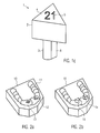
- FIG. 1 a shows a measuring body 1 with an upper hexagonal area and a lower round bar area 3.
- the round rod-shaped region 3 is to be inserted into an implant or an implant impression and the upper hexagonal region 2 is used for scanning.
- the sides of the hexagonal area are exactly the same length or are the same length with a precision of a few microns is very expensive.
- the dimensions D1, D2 and D3 are not all the same length, but rather vary intentionally or due to manufacturing tolerances.
- FIG. 1 b shows a measuring body 1 in which hemisphere elements 4 are additionally shown on the surface, which can serve to detect the position of the measuring body and / or to identify the measuring body.
- hemisphere elements 4 are additionally shown on the surface, which can serve to detect the position of the measuring body and / or to identify the measuring body.
- Such hemispherical shapes can be easily recognized during scanning and evaluated well with suitable matching software in order to precisely determine the respective position of these three hemispheres (or else 1, 2, 4, 5 or more hemispheres).
- the cross-sectional shape of area 2 need not be hexagonal. It may also be elliptical, circular, triangular, quadrangular, lenticular, pentagonal, octagonal, polygonal or otherwise irregular in shape.
- FIG. 1 c shows an example of a measuring body 1 which has a triangular cross-section in the region 2.
- the cross-sectional area does not have to remain constant along the axis of the measuring body, but the measuring body can also taper or widen upwards. For a scan, a taper upwards is to be preferred, because then the danger of shut down areas, which can not or only badly scanned, is avoided.
- the number 21 is engraved. It is given here in the form of a recess. But it can also be given in an increase.
- the number 21 stands here as representative of any alphanumeric or other (eg barcodes) identification of the measuring body 1.
- FIG. 1 c An additional detail is shown in FIG. 1 c, which, however, is independent of the shape of the region 2 or the design of the surface 4.
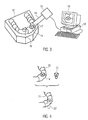
- FIG. 2 a shows a jaw impression 10 in the form of a model.
- the jaw appears here essentially toothless and has only one remaining tooth area 11.
- two openings 12 and 13 can be seen, with implant impressions located in these openings further down.
- these implant impressions are optically difficult to access optically in FIG. 2 a, so that their position and position can not or only poorly be recognized by a simple scanning of the jaw impression 10.
- FIG. 2 b shows the same jaw impression 10 with two measuring bodies 1 a, 1 b inserted.
- FIG. 3 A corresponding scanning process or a corresponding scanning device is shown schematically in FIG.
- the scanner in FIG. 3 is an optical scanner 15 by way of example.
- the optical scanner 15 can scan the surface of the jaw impression 10 in a line form 17 with a scanning light beam 16.
- Other optical scanners or mechanical probes can be used here.
- the data obtained by the scanner 15 are transmitted to a computer 18 and can there, z. B. on a screen 19, are displayed.
- the computer 18 is a data set, the individual shape of the measuring body 1 a and a data set, which reproduces the individual shape of the measuring body 1 b stored.
- FIG. 4 shows diagrammatically how a data record 20 obtained with the scanner 15 and a data record 21 stored on the computer 18 are merged to obtain a data record representing the shape of the residual tooth region 11 and additionally indicates the position and orientation of an implant 22.
- the position and orientation of the measuring body 1 a is determined, for example, by detecting the various flat areas of the hexagon and comparing the thus obtained scan data with the data set 21 on the computer 18. With z. B. a matching method, the
- Record 21 are fitted in the record 20. This results in a relation between the data record 20 and part of the data record 21 which corresponds to the second region 3 of the measuring body 1a. From this information about the position of this second area 3 can then be deduced the position of the corresponding implant 22.
- FIG. 3 shows that two different measuring bodies 1a, 1b are used simultaneously. However, it is also possible to first insert a measuring body 1 in the opening 12, then scan and then insert the same measuring body in the other opening 13 and scan again. Even then, the determination of position and orientation of the implant is possible.
- the data acquired during various scanning processes can be combined on the computer 18 with a corresponding matching method into larger data sets.
- the relative position of the two implants of the openings 12 and 13 to each other can be determined very precisely.
Landscapes
- Health & Medical Sciences (AREA)
- Life Sciences & Earth Sciences (AREA)
- General Health & Medical Sciences (AREA)
- Oral & Maxillofacial Surgery (AREA)
- Dentistry (AREA)
- Epidemiology (AREA)
- Veterinary Medicine (AREA)
- Animal Behavior & Ethology (AREA)
- Public Health (AREA)
- Orthopedic Medicine & Surgery (AREA)
- Optics & Photonics (AREA)
- Physics & Mathematics (AREA)
- Dental Tools And Instruments Or Auxiliary Dental Instruments (AREA)
- Dental Prosthetics (AREA)
- Prostheses (AREA)
Applications Claiming Priority (1)
| Application Number | Priority Date | Filing Date | Title |
|---|---|---|---|
| DE102006052419A DE102006052419A1 (de) | 2006-11-07 | 2006-11-07 | Verfahren zum Erfassen von Implantaten |
Publications (2)
| Publication Number | Publication Date |
|---|---|
| EP1920730A2 true EP1920730A2 (fr) | 2008-05-14 |
| EP1920730A3 EP1920730A3 (fr) | 2008-06-25 |
Family
ID=39106027
Family Applications (1)
| Application Number | Title | Priority Date | Filing Date |
|---|---|---|---|
| EP07021490A Withdrawn EP1920730A3 (fr) | 2006-11-07 | 2007-11-05 | Procédé de détermination de la position et de l'orientation d'un implant dentaire |
Country Status (6)
| Country | Link |
|---|---|
| US (1) | US20080176188A1 (fr) |
| EP (1) | EP1920730A3 (fr) |
| JP (1) | JP4755162B2 (fr) |
| AU (1) | AU2007231744B2 (fr) |
| CA (1) | CA2609890C (fr) |
| DE (1) | DE102006052419A1 (fr) |
Cited By (7)
| Publication number | Priority date | Publication date | Assignee | Title |
|---|---|---|---|---|
| EP2218423A1 (fr) * | 2009-02-12 | 2010-08-18 | Straumann Holding AG | Détermination de la position et de l'orientation d'un implant dentaire |
| DE102010062105A1 (de) * | 2010-11-29 | 2012-05-31 | Nt-Trading Gmbh & Co. Kg | Scankörper zur Bestimmung einer Positionierung und Orientierung eines Dentalimplantates |
| WO2014128054A1 (fr) * | 2013-02-20 | 2014-08-28 | Gc Europe | Aide pour implant dentaire précalibré |
| US8905757B2 (en) | 2012-12-03 | 2014-12-09 | E. Kats Enterprises Ltd. | Method and apparatus for measuring a location and orientation of a plurality of implants |
| EP3298983A1 (fr) * | 2016-09-21 | 2018-03-28 | Global Dental Science LLC | Système d'enregistrement d'orientation d'implants directement à partir d'une empreinte dentaire |
| US10390910B2 (en) | 2013-03-28 | 2019-08-27 | Dentsply Sirona Inc. | Integrated dental implant component and tool for placement of a dental implant component |
| US11850007B2 (en) | 2019-01-22 | 2023-12-26 | Stryker European Operations Holdings Llc | Tracker for a surgical navigation system |
Families Citing this family (40)
| Publication number | Priority date | Publication date | Assignee | Title |
|---|---|---|---|---|
| US8100692B2 (en) * | 2007-10-19 | 2012-01-24 | Cagenix Incorporated | Dental framework |
| DE102009014013B4 (de) * | 2009-03-23 | 2015-03-26 | Bego Implant Systems Gmbh & Co. Kg | Erfassungshilfskörper und dessen Verwendung zur Erfassung der Lage und Ausrichtung eines Implantats |
| US8867800B2 (en) | 2009-05-27 | 2014-10-21 | James R. Glidewell Dental Ceramics, Inc. | Method of designing and fabricating patient-specific restorations from intra-oral scanning of a digital impression |
| EP2324793A1 (fr) * | 2009-11-19 | 2011-05-25 | 3M Innovative Properties Company | Procédé et système pour la préparation d'une restauration dentaire, élément de mesure et leurs utilisations |
| ES2384247B1 (es) * | 2010-05-26 | 2013-05-13 | Ignacio De Medrano Reñe | Método para preparar la colocación de implantes dentales y elemento marcador utilizado en dicho método. |
| KR101214641B1 (ko) * | 2010-09-13 | 2012-12-21 | 주식회사 덴티스 | 임플란트 제조장치 및 그 제조방법 |
| EP2462893B8 (fr) * | 2010-12-07 | 2014-12-10 | Biomet 3i, LLC | Élément universel de référence pour balayage, à utiliser sur un implant dentaire et analogues d'implants dentaires |
| GB2486413B (en) * | 2010-12-13 | 2013-06-19 | Mordechi Shahak | Dental implant detector |
| WO2012126475A1 (fr) | 2011-03-18 | 2012-09-27 | Elos Medtech Pinol A/S | Butée dentaire pour le balayage buccal |
| WO2013061318A1 (fr) * | 2011-10-28 | 2013-05-02 | Navigate Surgical Technologies Inc. | Système et procédé de surveillance de champ opératoire |
| FI125322B (en) * | 2012-06-11 | 2015-08-31 | Planmeca Oy | Tooth Surface Models |
| DE102012105552A1 (de) * | 2012-06-26 | 2014-01-16 | Peter NEUMEIER | Vorrichtung und Verfahren zur Positions- und Lagebestimmung von Implantaten |
| US9549790B2 (en) | 2012-06-26 | 2017-01-24 | Gc Corporation | Scanning jig |
| GB201213384D0 (en) * | 2012-07-27 | 2012-09-12 | Nobel Biocare Services Ag | Method for making a dental component |
| EP2700377A1 (fr) * | 2012-08-20 | 2014-02-26 | Heraeus Kulzer GmbH | Element de référence pour la détermination de l'orientation et de la position d'un implant dentaire |
| JP2014198132A (ja) * | 2013-03-29 | 2014-10-23 | 株式会社ジーシー | スキャニング器具 |
| JP5710677B2 (ja) * | 2013-04-11 | 2015-04-30 | 昌義 古谷 | インプラント用トライアルゲージ |
| EP2842493B1 (fr) | 2013-08-30 | 2016-04-06 | Zfx GmbH | Corps de référence intra-orale |
| US10426711B2 (en) | 2014-05-08 | 2019-10-01 | Cagenix, Inc. | Dental implant framework |
| US10980618B2 (en) | 2014-05-08 | 2021-04-20 | Cagenix, Inc. | Dental framework and prosthesis |
| ES2989379T3 (es) | 2014-10-29 | 2024-11-26 | Armand Stemmer | Conjunto de cicatrización, serie de conjunto de cicatrización, procedimiento de fabricación de un pilar de restauración dental, dispositivo de restauración dental |
| KR101538289B1 (ko) * | 2014-11-04 | 2015-07-20 | 오세만 | 임플란트 상부 보철물 제작을 위한 3차원 스캔 데이터 추출용 임플란트 구조물 |
| WO2016126002A1 (fr) * | 2015-02-05 | 2016-08-11 | 오세만 | Structure d'implant pour extraire des données de balayage tridimensionnelles pour fabriquer une prothèse d'implant supérieure, et procédé de fabrication de prothèse l'utilisant |
| US9717570B2 (en) * | 2015-05-27 | 2017-08-01 | Felix Chung | Scan body for a dental impression |
| WO2017029670A1 (fr) * | 2015-08-17 | 2017-02-23 | Optical Metrology Ltd. | Cartographie intrabuccale de cavités buccales édentées ou partiellement édentées |
| ES3001092T3 (es) | 2015-10-21 | 2025-03-04 | Biomet 3I Llc | Método de diseño de una prótesis específica para un paciente y elemento de fijación para acoplarse a un implante dental |
| CN108135676B (zh) * | 2015-11-20 | 2021-08-06 | 诺贝尔生物服务公司 | 具有可扫描特征的愈合帽 |
| US10433936B2 (en) * | 2015-12-01 | 2019-10-08 | Evollution Ip Holdings, Inc. | Scan body with snap-in retention capability |
| US10912631B2 (en) | 2015-12-01 | 2021-02-09 | Evollution Ip Holdings, Inc. | Snap-coupling temporary abutment mount for dental prosthesis |
| EP3320878A1 (fr) * | 2016-11-10 | 2018-05-16 | Kulzer GmbH | Procédé amélioré de détection de la position et de repositionnement d'implants dentaires sous un format numérique dans le modèle respectif en format numérique |
| FR3063884B1 (fr) * | 2017-03-20 | 2021-12-17 | Euroteknika | Procede de restauration dentaire |
| KR102286354B1 (ko) * | 2017-06-19 | 2021-08-05 | 주식회사 메가젠임플란트 | 치과용 임플란트 구성품의 인식 겸용 검사 시스템 및 그 방법 |
| US12290423B2 (en) * | 2018-05-02 | 2025-05-06 | Naruto OTAWA | Scanning jig and method and system for identifying spatial position of implant or suchlike |
| CN108464873A (zh) * | 2018-05-21 | 2018-08-31 | 邱玟鑫 | 适用全口无牙之颜面扫描定位结构 |
| US20190374317A1 (en) * | 2018-06-06 | 2019-12-12 | Wen-Hsin Chiou | Face scanning and positioning structure used for full denture |
| US11364101B2 (en) | 2018-12-03 | 2022-06-21 | Cagenix, Inc. | Dental implant framework |
| IL268162A (en) * | 2019-07-18 | 2021-01-31 | Cortex Dental Implants Ind Ltd | Dental implant multifunctional abutment |
| EP4054470A4 (fr) * | 2019-11-04 | 2023-11-15 | Implant Solutions Pty Ltd | Appareil pour faciliter l'acquisition d'un balayage et d'une procédure de balayage intrabuccal |
| CN113483695B (zh) * | 2021-07-01 | 2024-01-26 | 先临三维科技股份有限公司 | 三维扫描系统、辅助件、处理方法、装置、设备及介质 |
| KR102523741B1 (ko) * | 2022-04-13 | 2023-04-20 | 송용준 | 힐링 임프레션 어버트먼트를 이용한 상부 보철 제작용 디지털 모형 구현 방법 |
Family Cites Families (17)
| Publication number | Priority date | Publication date | Assignee | Title |
|---|---|---|---|---|
| US4697245A (en) * | 1984-11-29 | 1987-09-29 | Cbit Corporation | Inspection and measuring apparatus and method |
| US5133660A (en) * | 1989-08-07 | 1992-07-28 | Fenick Thomas J | Device for locating the optimum position for a tooth implant |
| US5208845A (en) * | 1992-02-04 | 1993-05-04 | Gelb David A | Radiographic depth gauge |
| JPH0824685B2 (ja) * | 1992-11-25 | 1996-03-13 | 株式会社江川 | インプラント構造体の測定方法およびその測定装置 |
| SE502035C2 (sv) * | 1993-12-06 | 1995-07-24 | Nobelpharma Ab | Metod och och anordning för framtagning av information för framställning av artifiella stödorgan eller ersättningsdelar till människokroppen |
| BE1008372A3 (nl) * | 1994-04-19 | 1996-04-02 | Materialise Nv | Werkwijze voor het vervaardigen van een geperfektioneerd medisch model uitgaande van digitale beeldinformatie van een lichaamsdeel. |
| ATE234049T1 (de) * | 1997-10-31 | 2003-03-15 | Dcs Forschungs & Entwicklungs | Verfahren und vorrichtung zur herstellung eines zahnersatzteiles |
| CH694571A5 (de) * | 1999-06-21 | 2005-04-15 | Dcs Forschungs & Entwicklungs | Verfahren zur Herstellung eines Zahnersatzes und eines Zahnersatzteiles, Material für ein Zahnersatzteil und Zahnersatzteil. |
| US6506295B1 (en) * | 1999-10-06 | 2003-01-14 | Jonan Co., Ltd. | Cathodic protection method and device for metal structure |
| US6790040B2 (en) * | 1999-11-10 | 2004-09-14 | Implant Innovations, Inc. | Healing components for use in taking impressions and methods for making the same |
| DE19960020A1 (de) * | 1999-12-13 | 2001-06-21 | Ruediger Marmulla | Vorrichtung zur optischen Erfassung und Referenzierung zwischen Datensatz, Operationssitus und 3D-Markersystem zur Instrumenten- und Knochensegmentnavigation |
| US20020039718A1 (en) * | 2000-09-29 | 2002-04-04 | Biohex Corporation | Dental implant system and additional methods of attachment |
| DE60112245T2 (de) * | 2001-04-23 | 2006-03-30 | Cicero Dental Systems B.V. | Herstellungsverfahren für einen künstlichen Zahn |
| US6406295B1 (en) * | 2001-07-13 | 2002-06-18 | Brian A. Mahler | Identification of dental implant components |
| ITTO20030575A1 (it) * | 2003-07-25 | 2005-01-26 | Acom S R L | Procedimento per la fabbricazione di travate di protesi dentarie del tipo avvitato ad una pluralita' di impianti osteo-integrati nell'osso mandibolare o mascellare. |
| DE102004035091B4 (de) * | 2004-07-20 | 2017-10-26 | Sirona Dental Systems Gmbh | Verfahren zur Bestimmung der Lage und Orientierung der Achse eines direkt im Patientenmund befindlichen dentalen Implantats sowie Aufsatzteil hierfür |
| DE102005034803A1 (de) * | 2004-07-21 | 2006-03-16 | Wolfgang Gehrmann | Verfahren zur Herstellung von Zahnersatz |
-
2006
- 2006-11-07 DE DE102006052419A patent/DE102006052419A1/de not_active Withdrawn
-
2007
- 2007-11-05 EP EP07021490A patent/EP1920730A3/fr not_active Withdrawn
- 2007-11-06 CA CA2609890A patent/CA2609890C/fr not_active Expired - Fee Related
- 2007-11-07 AU AU2007231744A patent/AU2007231744B2/en not_active Ceased
- 2007-11-07 US US11/936,197 patent/US20080176188A1/en not_active Abandoned
- 2007-11-07 JP JP2007290183A patent/JP4755162B2/ja not_active Expired - Fee Related
Cited By (14)
| Publication number | Priority date | Publication date | Assignee | Title |
|---|---|---|---|---|
| KR101306027B1 (ko) * | 2009-02-12 | 2013-09-12 | 스트라우만 홀딩 에이쥐 | 치아 인플란트의 위치 및 방향 결정 |
| AU2010213079B2 (en) * | 2009-02-12 | 2012-11-01 | Straumann Holding Ag | Determining position and orientation of a dental implant |
| AU2010213079C1 (en) * | 2009-02-12 | 2013-05-30 | Straumann Holding Ag | Determining position and orientation of a dental implant |
| WO2010091868A1 (fr) * | 2009-02-12 | 2010-08-19 | Straumann Holding Ag | Détermination de position et d'orientation d'un implant dentaire |
| EP2218423A1 (fr) * | 2009-02-12 | 2010-08-18 | Straumann Holding AG | Détermination de la position et de l'orientation d'un implant dentaire |
| DE102010062105A1 (de) * | 2010-11-29 | 2012-05-31 | Nt-Trading Gmbh & Co. Kg | Scankörper zur Bestimmung einer Positionierung und Orientierung eines Dentalimplantates |
| EP2457536A3 (fr) * | 2010-11-29 | 2013-04-10 | nt-trading GmbH & Co. KG | Corps de balayage pour détermination de la position et de l'orientation d'un implant dentaire |
| US8801435B2 (en) | 2010-11-29 | 2014-08-12 | Nt-Trading Gmbh & Co. Kg | Scanbody for detecting the position and orientation of a dental implant |
| US8905757B2 (en) | 2012-12-03 | 2014-12-09 | E. Kats Enterprises Ltd. | Method and apparatus for measuring a location and orientation of a plurality of implants |
| WO2014128054A1 (fr) * | 2013-02-20 | 2014-08-28 | Gc Europe | Aide pour implant dentaire précalibré |
| US10390910B2 (en) | 2013-03-28 | 2019-08-27 | Dentsply Sirona Inc. | Integrated dental implant component and tool for placement of a dental implant component |
| EP3298983A1 (fr) * | 2016-09-21 | 2018-03-28 | Global Dental Science LLC | Système d'enregistrement d'orientation d'implants directement à partir d'une empreinte dentaire |
| US11850007B2 (en) | 2019-01-22 | 2023-12-26 | Stryker European Operations Holdings Llc | Tracker for a surgical navigation system |
| US11992272B2 (en) | 2019-01-22 | 2024-05-28 | Stryker European Operations Holdings Llc | Optical tracking device with optically distinguishable lines |
Also Published As
| Publication number | Publication date |
|---|---|
| JP2008142528A (ja) | 2008-06-26 |
| CA2609890A1 (fr) | 2008-05-07 |
| CA2609890C (fr) | 2011-06-07 |
| JP4755162B2 (ja) | 2011-08-24 |
| AU2007231744B2 (en) | 2010-01-28 |
| AU2007231744A1 (en) | 2008-05-22 |
| DE102006052419A1 (de) | 2008-05-08 |
| EP1920730A3 (fr) | 2008-06-25 |
| US20080176188A1 (en) | 2008-07-24 |
Similar Documents
| Publication | Publication Date | Title |
|---|---|---|
| EP1920730A2 (fr) | Procédé de détermination de la position et de l'orientation d'un implant dentaire | |
| EP3388021B1 (fr) | Procédé de détermination automatique d'une direction d'insertion pour une prothèse dentaire | |
| EP3589232B1 (fr) | Procédé de réalisation d'une restauration | |
| EP1618854B1 (fr) | Procédé et dispositif de détermination de la position et de l'orientation de l'axe d'un implant situé dans la bouche d'un patient | |
| DE69329584T2 (de) | Satz von Tragkernen für Zahnprothesen | |
| EP1920731A2 (fr) | Dispositif destiné à maintenir un modèle | |
| EP3471655B1 (fr) | Corps de scannage | |
| WO1998000072A1 (fr) | Implant dentaire et gabarit pour l'insertion d'un implant dentaire et leur procede d'obtention | |
| DE102011083439A1 (de) | Verfahren zur Überprüfung einer Bohrschablone zur Herstellung eines implantatgestützten Zahnersatzes | |
| EP2130514A1 (fr) | Pilier d'implant avec repères détectables par des moyens optiques et indiquants la position et l'orientation du pilier | |
| DE102009014013B4 (de) | Erfassungshilfskörper und dessen Verwendung zur Erfassung der Lage und Ausrichtung eines Implantats | |
| DE10019331B4 (de) | Vorrichtung mit einem Stabelement und einem pfostenförmigen Element | |
| EP2114288A1 (fr) | Procédé concernant des implants, support lisible par ordinateur et ordinateur approprié | |
| WO2021081574A1 (fr) | Corps de balayage ayant des repères d'orientation | |
| DE3918309C2 (de) | Schraubenimplantat für einen Kieferknochen | |
| EP2366360A1 (fr) | Raccord destiné à relier un implant dentaire et une prothèse dentaire, ainsi que sa fabrication | |
| EP0320740A2 (fr) | Implant de vis pour un os de la mâchoire | |
| WO2017028938A1 (fr) | Dispositif pour déterminer une angulation appropriée de butée pour implant dentaire et ensemble contenant un tel dispositif | |
| EP2594227A2 (fr) | Dispositif de prise d'empreinte et procédé de détection tridimensionnelle de structures intra-buccales ainsi qu'un dispositif de scanner correspondant | |
| DE202015009278U1 (de) | Zahnmedizinisches Implantat | |
| DE102007034653A1 (de) | Verfahren zum Entwerfen eines Zahnersatzteils, Verfahren zum Bearbeiten eines entworfenen Zahnersatzteils, Zahnersatzteil und computerlesbares Medium | |
| DE102007048356A1 (de) | Vorrichtung zum Halten eines Modellträgers eines Abutmentmodells | |
| CH714924A1 (de) | Kalibrierung verschiedener Geräte im digitalen Work-Flow eines Produktionsprozesses. | |
| DE102006010665A1 (de) | Herstellung von Zahnersatz | |
| DE10313690B4 (de) | Verarbeitung von Gestaltdaten einer Dentalprothese |
Legal Events
| Date | Code | Title | Description |
|---|---|---|---|
| PUAI | Public reference made under article 153(3) epc to a published international application that has entered the european phase |
Free format text: ORIGINAL CODE: 0009012 |
|
| AK | Designated contracting states |
Kind code of ref document: A2 Designated state(s): AT BE BG CH CY CZ DE DK EE ES FI FR GB GR HU IE IS IT LI LT LU LV MC MT NL PL PT RO SE SI SK TR |
|
| AX | Request for extension of the european patent |
Extension state: AL BA HR MK RS |
|
| PUAL | Search report despatched |
Free format text: ORIGINAL CODE: 0009013 |
|
| AK | Designated contracting states |
Kind code of ref document: A3 Designated state(s): AT BE BG CH CY CZ DE DK EE ES FI FR GB GR HU IE IS IT LI LT LU LV MC MT NL PL PT RO SE SI SK TR |
|
| AX | Request for extension of the european patent |
Extension state: AL BA HR MK RS |
|
| 17P | Request for examination filed |
Effective date: 20081223 |
|
| AKX | Designation fees paid |
Designated state(s): AT BE BG CH CY CZ DE DK EE ES FI FR GB GR HU IE IS IT LI LT LU LV MC MT NL PL PT RO SE SI SK TR |
|
| 17Q | First examination report despatched |
Effective date: 20090717 |
|
| RAP1 | Party data changed (applicant data changed or rights of an application transferred) |
Owner name: INSTITUT STRAUMANN AG |
|
| STAA | Information on the status of an ep patent application or granted ep patent |
Free format text: STATUS: THE APPLICATION IS DEEMED TO BE WITHDRAWN |
|
| 18D | Application deemed to be withdrawn |
Effective date: 20150117 |