EP1920849A2 - Dispositif de microextrusion, procédé pour former une structure extrudée et procédé de fabrication d'une matrice d'extrusion - Google Patents
Dispositif de microextrusion, procédé pour former une structure extrudée et procédé de fabrication d'une matrice d'extrusion Download PDFInfo
- Publication number
- EP1920849A2 EP1920849A2 EP07119720A EP07119720A EP1920849A2 EP 1920849 A2 EP1920849 A2 EP 1920849A2 EP 07119720 A EP07119720 A EP 07119720A EP 07119720 A EP07119720 A EP 07119720A EP 1920849 A2 EP1920849 A2 EP 1920849A2
- Authority
- EP
- European Patent Office
- Prior art keywords
- sheet
- extrusion
- substrate
- extruded
- outlet orifice
- Prior art date
- Legal status (The legal status is an assumption and is not a legal conclusion. Google has not performed a legal analysis and makes no representation as to the accuracy of the status listed.)
- Granted
Links
- 238000001125 extrusion Methods 0.000 title claims abstract description 121
- 238000000034 method Methods 0.000 title claims description 37
- 238000004519 manufacturing process Methods 0.000 title claims description 12
- 239000000463 material Substances 0.000 claims abstract description 98
- 239000000758 substrate Substances 0.000 claims abstract description 53
- 229910052751 metal Inorganic materials 0.000 claims abstract description 21
- 239000002184 metal Substances 0.000 claims abstract description 21
- 238000005530 etching Methods 0.000 claims description 17
- 238000001816 cooling Methods 0.000 claims description 3
- 238000010438 heat treatment Methods 0.000 claims description 2
- 210000004027 cell Anatomy 0.000 description 13
- BQCADISMDOOEFD-UHFFFAOYSA-N Silver Chemical compound [Ag] BQCADISMDOOEFD-UHFFFAOYSA-N 0.000 description 7
- 230000008569 process Effects 0.000 description 7
- 229910052709 silver Inorganic materials 0.000 description 7
- 239000004332 silver Substances 0.000 description 7
- 230000004888 barrier function Effects 0.000 description 6
- 239000006072 paste Substances 0.000 description 6
- 238000003754 machining Methods 0.000 description 5
- 230000008901 benefit Effects 0.000 description 4
- XUIMIQQOPSSXEZ-UHFFFAOYSA-N Silicon Chemical compound [Si] XUIMIQQOPSSXEZ-UHFFFAOYSA-N 0.000 description 3
- 230000015572 biosynthetic process Effects 0.000 description 3
- 238000007796 conventional method Methods 0.000 description 3
- 229920000642 polymer Polymers 0.000 description 3
- 238000012545 processing Methods 0.000 description 3
- 229910052710 silicon Inorganic materials 0.000 description 3
- 239000010703 silicon Substances 0.000 description 3
- PXHVJJICTQNCMI-UHFFFAOYSA-N Nickel Chemical compound [Ni] PXHVJJICTQNCMI-UHFFFAOYSA-N 0.000 description 2
- GWEVSGVZZGPLCZ-UHFFFAOYSA-N Titan oxide Chemical compound O=[Ti]=O GWEVSGVZZGPLCZ-UHFFFAOYSA-N 0.000 description 2
- 229910052782 aluminium Inorganic materials 0.000 description 2
- XAGFODPZIPBFFR-UHFFFAOYSA-N aluminium Chemical compound [Al] XAGFODPZIPBFFR-UHFFFAOYSA-N 0.000 description 2
- 230000006835 compression Effects 0.000 description 2
- 238000007906 compression Methods 0.000 description 2
- 235000014510 cooky Nutrition 0.000 description 2
- 238000000708 deep reactive-ion etching Methods 0.000 description 2
- 238000013461 design Methods 0.000 description 2
- 238000005323 electroforming Methods 0.000 description 2
- 239000012530 fluid Substances 0.000 description 2
- 239000011521 glass Substances 0.000 description 2
- 238000002347 injection Methods 0.000 description 2
- 239000007924 injection Substances 0.000 description 2
- 230000007246 mechanism Effects 0.000 description 2
- 238000012986 modification Methods 0.000 description 2
- 230000004048 modification Effects 0.000 description 2
- 235000014594 pastries Nutrition 0.000 description 2
- 238000001259 photo etching Methods 0.000 description 2
- 239000004033 plastic Substances 0.000 description 2
- 229920003023 plastic Polymers 0.000 description 2
- 239000004065 semiconductor Substances 0.000 description 2
- 239000007787 solid Substances 0.000 description 2
- PFNQVRZLDWYSCW-UHFFFAOYSA-N (fluoren-9-ylideneamino) n-naphthalen-1-ylcarbamate Chemical compound C12=CC=CC=C2C2=CC=CC=C2C1=NOC(=O)NC1=CC=CC2=CC=CC=C12 PFNQVRZLDWYSCW-UHFFFAOYSA-N 0.000 description 1
- WUPHOULIZUERAE-UHFFFAOYSA-N 3-(oxolan-2-yl)propanoic acid Chemical compound OC(=O)CCC1CCCO1 WUPHOULIZUERAE-UHFFFAOYSA-N 0.000 description 1
- JBRZTFJDHDCESZ-UHFFFAOYSA-N AsGa Chemical compound [As]#[Ga] JBRZTFJDHDCESZ-UHFFFAOYSA-N 0.000 description 1
- 229910052582 BN Inorganic materials 0.000 description 1
- PZNSFCLAULLKQX-UHFFFAOYSA-N Boron nitride Chemical compound N#B PZNSFCLAULLKQX-UHFFFAOYSA-N 0.000 description 1
- RYGMFSIKBFXOCR-UHFFFAOYSA-N Copper Chemical compound [Cu] RYGMFSIKBFXOCR-UHFFFAOYSA-N 0.000 description 1
- 229910002601 GaN Inorganic materials 0.000 description 1
- 229910001218 Gallium arsenide Inorganic materials 0.000 description 1
- JMASRVWKEDWRBT-UHFFFAOYSA-N Gallium nitride Chemical compound [Ga]#N JMASRVWKEDWRBT-UHFFFAOYSA-N 0.000 description 1
- GPXJNWSHGFTCBW-UHFFFAOYSA-N Indium phosphide Chemical compound [In]#P GPXJNWSHGFTCBW-UHFFFAOYSA-N 0.000 description 1
- 229910021578 Iron(III) chloride Inorganic materials 0.000 description 1
- 229910052581 Si3N4 Inorganic materials 0.000 description 1
- 229910000577 Silicon-germanium Inorganic materials 0.000 description 1
- 229910000831 Steel Inorganic materials 0.000 description 1
- ATJFFYVFTNAWJD-UHFFFAOYSA-N Tin Chemical compound [Sn] ATJFFYVFTNAWJD-UHFFFAOYSA-N 0.000 description 1
- 239000005083 Zinc sulfide Substances 0.000 description 1
- KTSFMFGEAAANTF-UHFFFAOYSA-N [Cu].[Se].[Se].[In] Chemical compound [Cu].[Se].[Se].[In] KTSFMFGEAAANTF-UHFFFAOYSA-N 0.000 description 1
- LEVVHYCKPQWKOP-UHFFFAOYSA-N [Si].[Ge] Chemical compound [Si].[Ge] LEVVHYCKPQWKOP-UHFFFAOYSA-N 0.000 description 1
- 238000010521 absorption reaction Methods 0.000 description 1
- FTWRSWRBSVXQPI-UHFFFAOYSA-N alumanylidynearsane;gallanylidynearsane Chemical compound [As]#[Al].[As]#[Ga] FTWRSWRBSVXQPI-UHFFFAOYSA-N 0.000 description 1
- MDPILPRLPQYEEN-UHFFFAOYSA-N aluminium arsenide Chemical compound [As]#[Al] MDPILPRLPQYEEN-UHFFFAOYSA-N 0.000 description 1
- PNEYBMLMFCGWSK-UHFFFAOYSA-N aluminium oxide Inorganic materials [O-2].[O-2].[O-2].[Al+3].[Al+3] PNEYBMLMFCGWSK-UHFFFAOYSA-N 0.000 description 1
- 238000013459 approach Methods 0.000 description 1
- 230000000903 blocking effect Effects 0.000 description 1
- 238000005219 brazing Methods 0.000 description 1
- 229910052980 cadmium sulfide Inorganic materials 0.000 description 1
- UHYPYGJEEGLRJD-UHFFFAOYSA-N cadmium(2+);selenium(2-) Chemical compound [Se-2].[Cd+2] UHYPYGJEEGLRJD-UHFFFAOYSA-N 0.000 description 1
- 239000006229 carbon black Substances 0.000 description 1
- 239000001913 cellulose Substances 0.000 description 1
- 229920002678 cellulose Polymers 0.000 description 1
- 239000000919 ceramic Substances 0.000 description 1
- 235000013339 cereals Nutrition 0.000 description 1
- 238000003486 chemical etching Methods 0.000 description 1
- 239000003795 chemical substances by application Substances 0.000 description 1
- 239000002131 composite material Substances 0.000 description 1
- 229910052802 copper Inorganic materials 0.000 description 1
- 239000010949 copper Substances 0.000 description 1
- 229910021419 crystalline silicon Inorganic materials 0.000 description 1
- 238000005520 cutting process Methods 0.000 description 1
- 229910003460 diamond Inorganic materials 0.000 description 1
- 239000010432 diamond Substances 0.000 description 1
- 238000009792 diffusion process Methods 0.000 description 1
- 238000001035 drying Methods 0.000 description 1
- 238000009713 electroplating Methods 0.000 description 1
- 238000005538 encapsulation Methods 0.000 description 1
- 238000011049 filling Methods 0.000 description 1
- 235000013305 food Nutrition 0.000 description 1
- 239000000446 fuel Substances 0.000 description 1
- 229910052732 germanium Inorganic materials 0.000 description 1
- GNPVGFCGXDBREM-UHFFFAOYSA-N germanium atom Chemical compound [Ge] GNPVGFCGXDBREM-UHFFFAOYSA-N 0.000 description 1
- 230000009477 glass transition Effects 0.000 description 1
- 238000000227 grinding Methods 0.000 description 1
- 239000012943 hotmelt Substances 0.000 description 1
- 239000012212 insulator Substances 0.000 description 1
- RBTARNINKXHZNM-UHFFFAOYSA-K iron trichloride Chemical compound Cl[Fe](Cl)Cl RBTARNINKXHZNM-UHFFFAOYSA-K 0.000 description 1
- 239000004816 latex Substances 0.000 description 1
- 229920000126 latex Polymers 0.000 description 1
- 239000007788 liquid Substances 0.000 description 1
- 238000005459 micromachining Methods 0.000 description 1
- 238000003801 milling Methods 0.000 description 1
- 238000002156 mixing Methods 0.000 description 1
- 229910052759 nickel Inorganic materials 0.000 description 1
- 239000012811 non-conductive material Substances 0.000 description 1
- 239000003921 oil Substances 0.000 description 1
- 230000003287 optical effect Effects 0.000 description 1
- 235000015927 pasta Nutrition 0.000 description 1
- 238000009304 pastoral farming Methods 0.000 description 1
- 229920003229 poly(methyl methacrylate) Polymers 0.000 description 1
- 239000004926 polymethyl methacrylate Substances 0.000 description 1
- 238000010248 power generation Methods 0.000 description 1
- 238000010791 quenching Methods 0.000 description 1
- 230000000171 quenching effect Effects 0.000 description 1
- 230000009467 reduction Effects 0.000 description 1
- 150000004760 silicates Chemical class 0.000 description 1
- HBMJWWWQQXIZIP-UHFFFAOYSA-N silicon carbide Chemical compound [Si+]#[C-] HBMJWWWQQXIZIP-UHFFFAOYSA-N 0.000 description 1
- 229910010271 silicon carbide Inorganic materials 0.000 description 1
- HQVNEWCFYHHQES-UHFFFAOYSA-N silicon nitride Chemical compound N12[Si]34N5[Si]62N3[Si]51N64 HQVNEWCFYHHQES-UHFFFAOYSA-N 0.000 description 1
- 238000005245 sintering Methods 0.000 description 1
- 235000011888 snacks Nutrition 0.000 description 1
- 229910001220 stainless steel Inorganic materials 0.000 description 1
- 239000010935 stainless steel Substances 0.000 description 1
- 239000010959 steel Substances 0.000 description 1
- 239000000126 substance Substances 0.000 description 1
- 229910052718 tin Inorganic materials 0.000 description 1
- 239000011135 tin Substances 0.000 description 1
- 239000004408 titanium dioxide Substances 0.000 description 1
- 239000000606 toothpaste Substances 0.000 description 1
- 239000005341 toughened glass Substances 0.000 description 1
- 238000012546 transfer Methods 0.000 description 1
- 239000001993 wax Substances 0.000 description 1
- 229910052984 zinc sulfide Inorganic materials 0.000 description 1
- DRDVZXDWVBGGMH-UHFFFAOYSA-N zinc;sulfide Chemical compound [S-2].[Zn+2] DRDVZXDWVBGGMH-UHFFFAOYSA-N 0.000 description 1
Images


Classifications
-
- B—PERFORMING OPERATIONS; TRANSPORTING
- B81—MICROSTRUCTURAL TECHNOLOGY
- B81C—PROCESSES OR APPARATUS SPECIALLY ADAPTED FOR THE MANUFACTURE OR TREATMENT OF MICROSTRUCTURAL DEVICES OR SYSTEMS
- B81C1/00—Manufacture or treatment of devices or systems in or on a substrate
- B81C1/00436—Shaping materials, i.e. techniques for structuring the substrate or the layers on the substrate
- B81C1/00634—Processes for shaping materials not provided for in groups B81C1/00444 - B81C1/00626
-
- B—PERFORMING OPERATIONS; TRANSPORTING
- B81—MICROSTRUCTURAL TECHNOLOGY
- B81C—PROCESSES OR APPARATUS SPECIALLY ADAPTED FOR THE MANUFACTURE OR TREATMENT OF MICROSTRUCTURAL DEVICES OR SYSTEMS
- B81C1/00—Manufacture or treatment of devices or systems in or on a substrate
-
- B—PERFORMING OPERATIONS; TRANSPORTING
- B29—WORKING OF PLASTICS; WORKING OF SUBSTANCES IN A PLASTIC STATE IN GENERAL
- B29C—SHAPING OR JOINING OF PLASTICS; SHAPING OF MATERIAL IN A PLASTIC STATE, NOT OTHERWISE PROVIDED FOR; AFTER-TREATMENT OF THE SHAPED PRODUCTS, e.g. REPAIRING
- B29C48/00—Extrusion moulding, i.e. expressing the moulding material through a die or nozzle which imparts the desired form; Apparatus therefor
- B29C48/03—Extrusion moulding, i.e. expressing the moulding material through a die or nozzle which imparts the desired form; Apparatus therefor characterised by the shape of the extruded material at extrusion
- B29C48/07—Flat, e.g. panels
-
- B—PERFORMING OPERATIONS; TRANSPORTING
- B29—WORKING OF PLASTICS; WORKING OF SUBSTANCES IN A PLASTIC STATE IN GENERAL
- B29C—SHAPING OR JOINING OF PLASTICS; SHAPING OF MATERIAL IN A PLASTIC STATE, NOT OTHERWISE PROVIDED FOR; AFTER-TREATMENT OF THE SHAPED PRODUCTS, e.g. REPAIRING
- B29C48/00—Extrusion moulding, i.e. expressing the moulding material through a die or nozzle which imparts the desired form; Apparatus therefor
- B29C48/03—Extrusion moulding, i.e. expressing the moulding material through a die or nozzle which imparts the desired form; Apparatus therefor characterised by the shape of the extruded material at extrusion
- B29C48/12—Articles with an irregular circumference when viewed in cross-section, e.g. window profiles
-
- B—PERFORMING OPERATIONS; TRANSPORTING
- B81—MICROSTRUCTURAL TECHNOLOGY
- B81C—PROCESSES OR APPARATUS SPECIALLY ADAPTED FOR THE MANUFACTURE OR TREATMENT OF MICROSTRUCTURAL DEVICES OR SYSTEMS
- B81C99/00—Subject matter not provided for in other groups of this subclass
- B81C99/0005—Apparatus specially adapted for the manufacture or treatment of microstructural devices or systems, or methods for manufacturing the same
- B81C99/0015—Apparatus specially adapted for the manufacture or treatment of microstructural devices or systems, or methods for manufacturing the same for microextrusion
-
- B—PERFORMING OPERATIONS; TRANSPORTING
- B29—WORKING OF PLASTICS; WORKING OF SUBSTANCES IN A PLASTIC STATE IN GENERAL
- B29C—SHAPING OR JOINING OF PLASTICS; SHAPING OF MATERIAL IN A PLASTIC STATE, NOT OTHERWISE PROVIDED FOR; AFTER-TREATMENT OF THE SHAPED PRODUCTS, e.g. REPAIRING
- B29C49/00—Blow-moulding, i.e. blowing a preform or parison to a desired shape within a mould; Apparatus therefor
- B29C49/02—Combined blow-moulding and manufacture of the preform or the parison
- B29C2049/023—Combined blow-moulding and manufacture of the preform or the parison using inherent heat of the preform, i.e. 1 step blow moulding
-
- B—PERFORMING OPERATIONS; TRANSPORTING
- B29—WORKING OF PLASTICS; WORKING OF SUBSTANCES IN A PLASTIC STATE IN GENERAL
- B29C—SHAPING OR JOINING OF PLASTICS; SHAPING OF MATERIAL IN A PLASTIC STATE, NOT OTHERWISE PROVIDED FOR; AFTER-TREATMENT OF THE SHAPED PRODUCTS, e.g. REPAIRING
- B29C48/00—Extrusion moulding, i.e. expressing the moulding material through a die or nozzle which imparts the desired form; Apparatus therefor
- B29C48/001—Combinations of extrusion moulding with other shaping operations
- B29C48/0013—Extrusion moulding in several steps, i.e. components merging outside the die
- B29C48/0015—Extrusion moulding in several steps, i.e. components merging outside the die producing hollow articles having components brought in contact outside the extrusion die
- B29C48/0016—Extrusion moulding in several steps, i.e. components merging outside the die producing hollow articles having components brought in contact outside the extrusion die using a plurality of extrusion dies
-
- B—PERFORMING OPERATIONS; TRANSPORTING
- B29—WORKING OF PLASTICS; WORKING OF SUBSTANCES IN A PLASTIC STATE IN GENERAL
- B29C—SHAPING OR JOINING OF PLASTICS; SHAPING OF MATERIAL IN A PLASTIC STATE, NOT OTHERWISE PROVIDED FOR; AFTER-TREATMENT OF THE SHAPED PRODUCTS, e.g. REPAIRING
- B29C48/00—Extrusion moulding, i.e. expressing the moulding material through a die or nozzle which imparts the desired form; Apparatus therefor
- B29C48/03—Extrusion moulding, i.e. expressing the moulding material through a die or nozzle which imparts the desired form; Apparatus therefor characterised by the shape of the extruded material at extrusion
- B29C48/09—Articles with cross-sections having partially or fully enclosed cavities, e.g. pipes or channels
-
- B—PERFORMING OPERATIONS; TRANSPORTING
- B29—WORKING OF PLASTICS; WORKING OF SUBSTANCES IN A PLASTIC STATE IN GENERAL
- B29C—SHAPING OR JOINING OF PLASTICS; SHAPING OF MATERIAL IN A PLASTIC STATE, NOT OTHERWISE PROVIDED FOR; AFTER-TREATMENT OF THE SHAPED PRODUCTS, e.g. REPAIRING
- B29C48/00—Extrusion moulding, i.e. expressing the moulding material through a die or nozzle which imparts the desired form; Apparatus therefor
- B29C48/16—Articles comprising two or more components, e.g. co-extruded layers
- B29C48/18—Articles comprising two or more components, e.g. co-extruded layers the components being layers
- B29C48/19—Articles comprising two or more components, e.g. co-extruded layers the components being layers the layers being joined at their edges
-
- B—PERFORMING OPERATIONS; TRANSPORTING
- B29—WORKING OF PLASTICS; WORKING OF SUBSTANCES IN A PLASTIC STATE IN GENERAL
- B29C—SHAPING OR JOINING OF PLASTICS; SHAPING OF MATERIAL IN A PLASTIC STATE, NOT OTHERWISE PROVIDED FOR; AFTER-TREATMENT OF THE SHAPED PRODUCTS, e.g. REPAIRING
- B29C48/00—Extrusion moulding, i.e. expressing the moulding material through a die or nozzle which imparts the desired form; Apparatus therefor
- B29C48/16—Articles comprising two or more components, e.g. co-extruded layers
- B29C48/18—Articles comprising two or more components, e.g. co-extruded layers the components being layers
- B29C48/21—Articles comprising two or more components, e.g. co-extruded layers the components being layers the layers being joined at their surfaces
-
- B—PERFORMING OPERATIONS; TRANSPORTING
- B29—WORKING OF PLASTICS; WORKING OF SUBSTANCES IN A PLASTIC STATE IN GENERAL
- B29C—SHAPING OR JOINING OF PLASTICS; SHAPING OF MATERIAL IN A PLASTIC STATE, NOT OTHERWISE PROVIDED FOR; AFTER-TREATMENT OF THE SHAPED PRODUCTS, e.g. REPAIRING
- B29C48/00—Extrusion moulding, i.e. expressing the moulding material through a die or nozzle which imparts the desired form; Apparatus therefor
- B29C48/25—Component parts, details or accessories; Auxiliary operations
- B29C48/88—Thermal treatment of the stream of extruded material, e.g. cooling
- B29C48/911—Cooling
- B29C48/9135—Cooling of flat articles, e.g. using specially adapted supporting means
-
- B—PERFORMING OPERATIONS; TRANSPORTING
- B29—WORKING OF PLASTICS; WORKING OF SUBSTANCES IN A PLASTIC STATE IN GENERAL
- B29C—SHAPING OR JOINING OF PLASTICS; SHAPING OF MATERIAL IN A PLASTIC STATE, NOT OTHERWISE PROVIDED FOR; AFTER-TREATMENT OF THE SHAPED PRODUCTS, e.g. REPAIRING
- B29C49/00—Blow-moulding, i.e. blowing a preform or parison to a desired shape within a mould; Apparatus therefor
- B29C49/02—Combined blow-moulding and manufacture of the preform or the parison
- B29C49/06—Injection blow-moulding
- B29C49/061—Injection blow-moulding with parison holding means displaceable between injection and blow stations
-
- B—PERFORMING OPERATIONS; TRANSPORTING
- B81—MICROSTRUCTURAL TECHNOLOGY
- B81B—MICROSTRUCTURAL DEVICES OR SYSTEMS, e.g. MICROMECHANICAL DEVICES
- B81B2203/00—Basic microelectromechanical structures
- B81B2203/03—Static structures
- B81B2203/0369—Static structures characterized by their profile
- B81B2203/0376—Static structures characterized by their profile rounded profile
Definitions
- the present invention is related to extrusion systems and methods, and more particularly to micro extrusion systems and methods for co-extruding multiple similar and/or dissimilar materials to form relatively fine structures with relatively high aspect ratios.
- extrusion can be used with food processing applications to create pasta, cereal, snacks, etc., pipe pastry filling (e.g., meringue), pattern cookie dough on a cookie pan, generate pastry flowers and borders on cakes, etc.
- extrusion can be used with consumer goods, for example, to merge different colored toothpastes together on a toothbrush.
- Fig. 11 is a perspective view showing an extrusion head 30 of a conventional micro extrusion system for producing fine featured (e.g., less than 50 micron width and height) structures 20 on the upper surface 102 of a substrate 101.
- Extrusion head 30 that includes metal plates 31, 32 and 33 that are laminated together using known high pressure wafer bonding techniques, with one or more of the plates being processed to define a fluidic channel 34 that communicates with an outlet orifice 35 that is defined on a side edge of the head.
- Extrusion material is inserted into fluidic channels 34 through an input port 37 such that the extrusion materials are shaped and extruded through outlet orifice 35, from which they are dispensed onto a target structure (e.g., upper surface 102 of substrate 101).
- Figs. 12(A) and 12(B) are cross sectional side views illustrating a typical production problem associated with conventional micro extrusion systems.
- Fig. 12(A) shows an idealized high aspect-ratio extruded structure 20A formed on substrate 101 using the conventional micro extrusion techniques described above, with idealized extruded structure 20A having the square or rectangular shape of outlet orifice 35.
- idealized extruded structure 20A that has a relatively narrow width W1 and a relatively large height H.
- a problem with the production of micro extrusion structures is that the extruded material is necessarily a fluid (i.e., liquid or paste), and as such is subjected to settling after being extruded. Therefore, the ideal rectangular shape shown in Fig.
- extrusion typically is not used for creating conducting contacts and/or channels for electrochemical (e.g., fuel), solar, and/or other types of cells, which leverage high aspect-ratio fine featured porous structures to increase efficiency and electrical power generation.
- aspect-ratio e.g. 1:1 or greater
- porous structures for a cost below $1/sq. ft.
- extrusion typically is not used for creating conducting contacts and/or channels for electrochemical (e.g., fuel), solar, and/or other types of cells, which leverage high aspect-ratio fine featured porous structures to increase efficiency and electrical power generation.
- FIG. 13 Another practical device that benefits from rapid and economical means for generating high aspect ratio lines and features include plasma display panels, such as that shown in Fig. 13, where high aspect-ratio barrier ribs define the sub-pixels within the display.
- the barrier rib is an electrically insulating structure, and is preferably a high aspect ratio structure, as this improves the dot per inch resolution and fill factor of the display.
- the settling problem discussed above with reference to Fig. 12(B) results in non-optimal barrier ribs that produce inferior display devices.
- the present invention is directed to an apparatus and a method for forming high-aspect ratio functional structures (e.g., "gridlines") on a substrate surface in which the gridlines are extruded through an orifice of an extrusion head, wherein the orifice has an oblique (e.g., curved or tapered) upper surface that causes the gridlines to have a curved or tapered upper surface immediately upon extrusion.
- the extrusion head is fabricated using several (e.g., metal) sheets that are bonded or otherwise laminated together. One of the sheets is etched to define the oblique surface of the orifice, and that sheet is then bonded to a second sheet to provide a flat lower surface of the orifice.
- the oblique upper surface of the orifice is formed such that the gridlines are substantially in equilibrium immediately after being extruded, thus preventing undesirable subsequent settling that increases the width and reduces the height.
- a gridline (functional) material is co-extruded with a support (e.g., sacrificial) material onto the substrate surface such that the high-aspect ratio gridline is supported between two support material portions (in one embodiment the support portions are treated as sacrificial portions that are subsequently removed).
- a support e.g., sacrificial
- the formation of such co-extruded structures requires the compression of the gridline material between the two support material portions, which requires the use of a relatively wide three-channel cavity feeding a relatively narrow outlet orifice in a manner that compresses the gridline material between the two support material portions.
- the present invention facilitates the reliable production of high aspect-ratio gridlines.
- providing the extrusion head comprises fixedly mounting the extrusion head on an extrusion device coupled to a source of the extruded material.
- the method further comprises at least one of heating the extruded materials prior to extrusion, cooling the substrate during extrusion, and curing the extruded materials.
- the fluidic channel comprises a three-channel cavity including a central channel and opposing first and second side channels, wherein each of the central channel and the first and second side channels comprise an associated said elongated trench and communicate with the outlet orifice, and wherein forcing the material through the fluidic channel comprises injecting functional material into the central channel of the three-channel cavity while injecting the support material into the opposing first and second side channels of the three-channel cavity such that said functional material extruded from the outlet orifice forms an associated high aspect ratio functional structure of said extruded structure, and said support material extruded from the outlet orifice forms associated first and second support material portions respectively disposed on opposing sides of said associated functional structure.
- the first sheet defines a first and second inlet ports respectively communicating with the first and second side channels of the three-channel cavity
- the extrusion head further comprises a third sheet having a third inlet port communicating with the central channel of the three-channel cavity
- injecting the functional material and the support material further comprises forcing the functional material through the third inlet port into the central channel while forcing the support material through the first and second inlet ports into the first and second side channels, respectively.
- the second sheet further defines an inlet opening disposed in the elongated trench adjacent to the closed end and extending entirely through the second sheet, and wherein injecting the functional material includes forcing the functional material through both the third inlet port and the inlet opening into the central channel.
- a method for manufacturing an extrusion head for a micro extrusion apparatus includes etching a first sheet to include an elongated trench having an oblique (e.g., generally semi-cylindrical or tapered) shape.
- the trench has a closed end, and extends to a side edge of the sheet.
- a second sheet is etched to include an inlet port that is positioned to align with the closed end of the trench when the first and second sheets are bonded together.
- the oblique trench is thus formed in a reliable and economical manner, and serves to provide an orifice having an oblique surface that is defined in a side edge of the extrusion head.
- etching the first sheet comprises one of photochemical machining, pulsed laser machining, deep reactive ion etching, electro-discharge machining and anisotropic etching.
- etching the first sheet comprises forming three elongated trenches including a central trench and opposing first and second side trenches, wherein each of the central trench and the first and second side trenches extend from the side edge to an associated opposing closed end.
- etching the second sheet comprises forming first and second inlet ports disposed such that the first inlet port is aligned with the closed end of the first side trench and the second inlet port is aligned with the closed end of the second side trench after said bonding.
- etching the second sheet further comprises forming an inlet opening disposed in the central elongated trench adjacent to its closed end and extending entirely through the second sheet, and wherein the method further comprises etching a third sheet such that the third sheet includes a third inlet port passing entirely through the second sheet, and wherein bonding the first sheet to the second sheet further comprises bonding the third sheet to a second side of the first sheet such that the third inlet port is aligned with the inlet opening.
- FIGURE 1 is an assembled perspective view showing a portion of a co-extrusion head of a micro extrusion system according to an embodiment of the present invention
- FIGURE 2 is an exploded perspective view showing the portion of the co-extrusion head of FIGURE 1;
- FIGURE 3 is a perspective view showing a micro extrusion apparatus including the co-extrusion head of FIGURE 1 for concurrently applying two or more materials on a substrate;
- FIGURES 4(A) and 4(B) are cross-sectional side views showing a three-channel cavity defined in the co-extrusion head of FIGURE 1;
- FIGURE 5 is a cross-sectional side view showing an exemplary co-extruded gridline structure that was generated on a substrate surface by the co-extrusion head of FIGURE 4(B);
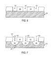
- FIGURE 6 is a cross-sectional side view showing a sheet including a first mask used to form trenches according to an embodiment of the present invention
- FIGURE 7 is a cross-sectional side view showing an etching process for forming trenches using the first mask shown in Fig. 6;
- FIGURE 8 is a cross-section side view showing a second mask and second etching process used to form an inlet opening into a central trench of the sheet shown in Fig. 7;
- FIGURE 9 is a cross-sectional side view showing a portion of an extrusion head including the sheet formed in Fig. 8;
- FIGURE 10 illustrates a photovoltaic cell including gridlines formed in accordance with the present invention
- FIGURE 11 is perspective view showing a portion of a conventional micro extrusion head
- FIGURES 12(A) and 12(B) are simplified cross-sectional side views showing extruded structures formed by the conventional head shown in Fig. 11;
- FIGURE 13 is a simplified cross-sectional side view showing a portion of an exemplary plasma display panel.
- FIGURE 1 illustrates a portion of an extrusion head 130, which makes up part of a micro extrusion apparatus 100 for producing an extruded structures 120 having an equilibrium shape on a substrate 101 in accordance with an embodiment of the present invention.
- Extrusion head 130 is operably coupled to one or more sources (not shown) of extrusion materials such that the material is extruded from an outlet orifice 135 defined in a side edge 139 of extrusion head 130, and is deposited onto the upper surface 102 of substrate 101 with the desired equilibrium shape that resists settling after extrusion.
- Fig. 2 is an exploded perspective view showing extrusion head 130 in additional detail.
- extrusion head 130 is made up of multiple sheets (substrates or plates) 210, 220 and 230 that, in one embodiment, are bonded using known high pressure wafer bonding techniques to form the substantially solid, block-like structure shown in Fig. 1.
- sheets 210, 220 and 230 are metal plates having a thickness of approximately 0.15 mm.
- Each of the sheets has opposing sides and a substantially straight side edge--sheet 210 has opposing first and second surfaces 211-1 and 211-2 and a side edge 219
- sheet 220 has opposing surfaces 221-1 and 221-2 and a side edge 229
- sheet 230 has opposing surfaces 231-1 and 231-2 and a side edge 239.
- Sheets 210, 220, and 230 are bonded such that sheet 230 is sandwiched between sheet 210 and 220, with sheet 230 being mounted on sheet 220 such that surface 231-1 faces surface 221-2, and sheet 210 being mounted on sheet 230 such that (first) surface 211-1 faces (second) surface 231-2.
- Sheets 210, 220 and 230 are assembled or processed (e.g., by one or more of cutting, milling or grinding) such that side edges 219, 229 and 239 are aligned to form a edge surface 139 of extrusion head 130, as indicated in Fig. 1.
- a method for fabricating head 130 is described in co-owned and co-pending U.S. Patent Application No. xx/xxx, xxx, entitled “EXTRUSION HEAD WITH PLANARIZED EDGE SURFACE” [Atty Docket No. 20060464Q-US-NP (XCP-074)], which is incorporated herein by reference in its entirety.
- sheet 230 is etched or otherwise manufactured to include at least one of elongated trenches 232, 233 and 234 that are defined in surface 232-2, and extending from an open end (notch) 235 located adjacent to side edge 239 to a closed end disposed away from side edge 239.
- Each trench 232, 233 and 234 has a concave oblique (e.g., generally semi-cylindrical or tapered) surface that is formed in the manner described below.
- trench 232 includes an oblique surface 231-22
- trench 233 includes an oblique surface 231-23
- trench 234 includes an oblique surface 231-24.
- planar flat portions 231-21 of second surface 232-2 abut first surface 211-1 of sheet 210, and each trench 232, 233 and 234 combines with opposing flat portions 211-12, 211-13 and 211-14, respectively, of surface 211-1 to form a generally semi-cylindrical fluidic channel (e.g., fluidic channels 132, 133, 134, indicated in Fig. 1), with each fluidic channel communicating with an associated outlet orifice 135.
- fluidic channels 132, 133, 134 indicated in Fig. 1
- outlet orifice 135 includes a straight edge 136 that is defined by the portion of flat surface 211-1 located at side edge 219 of sheet 210, and an oblique second edge 137 defined by end portions of oblique surfaces 232-22, 232-23, and/or 232-24 that are located at side edge 239 of sheet 230.
- Oblique edge 137 facilitates the production of extruded structures having an equilibrium shape in the manner described below.
- trenches 232, 233 and 234 are arranged in an arrowhead-shaped pattern such that, when extrusion head 130 is assembled, a fluidic channel 130-1 is formed as a three-channel cavity having central channel 132 positioned between opposing (first and second) side channels 133 and 134, with all three channels communicating with output port 135.
- central trench 232 is separated from side trenches 233 and 234 by tapered finger-like flat portions 232-211 and 232-212, respectively, and trench 232 is closed by an end flat portion 232-313, thereby form central channel 132 when sheets 210 and 230 are combined.
- side trenches 233 and 234 are closed by corresponding surrounding flat portions of sheet 210 to form opposing side channels 133 and 134.
- Side channels 133 and 134 are angled toward central channel 132, and converge at a point adjacent to notch 235, which cooperates with sheet 210 to form outlet orifice 135.
- the disclosed embodiment depicts three intercommunicating trenches/channels arranged in an arrowhead shape, aspects of the present invention apply to any number of trenches/channels (e.g., one single trench/channel communicating with outlet orifice 135).
- extrusion head 130 is moved relative to substrate 101 (e.g., in the direction of arrow A) while one or more extrusion materials (not shown) are forced through fluidic channels 132, 133 and 134 such that the material is extruded from outlet orifice 135 and forms an associated extruded structure 120 on substrate 101.
- extrusion material is forced through inlets located adjacent to the closed ends of each fluidic channel 132, 133 and 134 using known techniques. Referring to Fig. 2, the inlet ports used to communicate with the fluidic channels are etch or otherwise formed in the various sheets.
- sheet 210 defines inlet ports (e.g., through holes, slots or channels) 213 and 214 that are aligned with the closed ends of trenches 233 and 234, respectively, and sheet 220 defines an inlet port 222-1 that is aligned with central trench 232.
- An inlet opening 222-2 is formed inside central trench 232 that extends through the thin remaining wall of sheet 230 and aligns with inlet port 222-1 when sheets 210 and 230 are joined.
- Inlet ports 213, 214, 222-1 and 222-2 are formed, for example, using micro-machining techniques (e.g., photo-chemical machining, pulsed laser machining, deep reactive ion etching, electro-discharge machining or anisotropic etching).
- extruded structure 120 due to the shape of fluidic channels 132, 133 and 134 and outlet orifice 135, extruded structure 120 (shown in Fig. 1) has an equilibrium shape upon extrusion, thus avoiding the settling problems associated with conventional micro extrusion techniques.
- extruded structure 120 has a flat lower surface 126 (i.e., the surface in contact with upper surface 102 of substrate 101) that is formed by flat edge 136 of outlet orifice 135, and a curved or tapered upper surface 127 that is formed by the oblique edge 137 of outlet orifice 135 and faces away from substrate 101.
- the rectangular shaped initial extrusion structure 20A Fig.
- extruded structure 120 is extruded in a shape that is close to structural equilibrium, thereby resisting settling and facilitating the production of extruded structures that have a relatively uniform and reliably consistent height and width.
- extrusion head 130 can be manufactured a variety of ways. For example, rounded channels can be formed by electroforming metal over resist structures that have been reflowed above their glass transition temperature. Tapered channels can also be formed by electroforming metal over resist structures that are processed using known techniques for creating a tapered sidewall.
- an extrusion head formed in accordance with the present invention can be manufactured by brazing together layers of etched sheet metal.
- the heads can be manufactured by generating structures out of photo-definable polymer such as SU8.
- the heads can be machined or molded out of metal and/or plastic using conventional manufacturing techniques.
- FIGURE 3 illustrates micro extrusion apparatus 100A in accordance with another embodiment of the present invention.
- Apparatus 100A includes an extrusion device 110 having one or more co-extrusion heads 130-1 and 130-2 fixedly mounted thereon, each co-extrusion head 130-1 and 130-2 being consistent with extrusion head 130, described above.
- extrusion device 110 is coupled to a first source 111 containing a support material 112, and a second source 114 containing a functional ("gridline") material 115.
- Extrusion heads 130-1 and 130-2 are operably coupled to sources 111 and 114 such that heads 130-1 and 130-2 concurrently apply support material 112 and a gridline material 115 onto the upper surface 102 of a substrate 101.
- the materials are applied through pushing and/or drawing techniques (e.g., hot and cold) in which the materials are pushed (e.g., squeezed, etc.) and/or drawn (e.g., via a vacuum, etc.) through extrusion device 110 and/or co-extrusion heads 130-1 and 130-2, and out outlet orifices 135 that are respectively defined in a lower portion of co-extrusion heads 130-1 and 130-2.
- pushing and/or drawing techniques e.g., hot and cold
- the materials are pushed (e.g., squeezed, etc.) and/or drawn (e.g., via a vacuum, etc.) through extrusion device 110 and/or co-extrusion heads 130-1 and 130-2, and out outlet orifices 135 that are respectively defined in a lower portion of co-extrusion heads 130-1 and 130-2.
- co-extrusion heads 130-1 and 130-2 are held by extrusion device 110 such that their respective outlet orifices are arranged in a parallel, spaced-apart arrangement.
- the (first) outlet orifices of co-extrusion head 130-1 e.g., outlet orifices 135-11 and 135-12
- the (second) outlet orifices of the second co-extrusion head 130-2 e.g., outlet orifices 135-21 and 135-22
- second line X2 that is separated from and parallel to first line X1.
- apparatus 100A includes a mechanism (not shown) for moving extrusion device 110 (and, hence, co-extrusion heads 130-1 and 130-2) in a direction that is perpendicular to the alignment direction of the outlet orifices, and gridline material 115 and support material 112 are co-extruded through outlet orifices 135 in a manner that creates parallel, elongated extruded structures 120A on substrate 101 such that the gridline material of each structure 120A forms a high-aspect ratio gridline structure 125, and the support material of each structure 120A forms associated first and second support material portions 122 respectively disposed on opposing sides of the associated high-aspect ratio gridline 125.
- extruded structures 120A i.e., the aspect ratio of gridline 125 and the shape of support portions 122 are controlled by the shape outlet orifices 135 and the fluidic channels inside heads 130-1 and 130-2, characteristics of the materials (e.g., viscosity, etc.), and the extrusion technique (e.g., flow rate, pressure, temperature, etc.) to achieve the equilibrium shape mentioned above and described in additional detail below.
- the structure within heads 130-1 and 130-2 and the shape of outlet orifices 135 is consistent with that described above with reference to Figs. 1 and 2.
- Suitable gridline materials 115 include, but are not limited to, silver, copper, nickel, tin, aluminum, steel, alumina, silicates, glasses, carbon black, polymers and waxes, and suitable support materials 112 include plastic, ceramic, oil, cellulose, latex, polymethylmethacrylate etc., combinations thereof, and/or variations thereof, including combining the above with other substances to obtain a desired density, viscosity, texture, color, etc.
- the outlet orifices of co-extrusion heads 130-1 and 130-2 are disposed in a staggered arrangement to simultaneously generate extrusion structures 120A that are closely spaced, thus facilitating the production of high aspect-ratio gridlines 125 are formed on substrate 101 at a pitch that is not possible using conventional methods.
- a single head may be used to produce extrusion structures 120A that are spaced relatively far apart.
- extruded structures 120A leaving extrusion heads 130-1 and 130-2 can be quenched on substrate 101 by cooling the substrate using, for example, a quenching component 170.
- the ink/paste used in this application may be a hotmelt material, which solidifies at ambient temperatures, in which case the printheads 130-1 and 130-2 are heated, leaving the extruded structures 120A to solidify once they are dispensed onto the substrate 101.
- the materials can be cured by thermal, optical and/or other means upon exit from extrusion heads 130-1 and 130-2.
- a curing component 180 can be provided to thermally and/or optically cure the materials. If one or both materials include an ultraviolet curing agent, the material can be bound up into solid form in order to enable further processing without mixing.
- Fig. 4(A) shows a portion of co-extrusion head 130-1 including fluidic channel 130-11 positioned over substrate 101 prior to generation of metal gridlines.
- Co-extrusion head 130-1 is maintained at a substantially fixed distance D over upper surface 102 of substrate 101 during the extrusion process (i.e., while co-extrusion head 130-1 is moved relative to substrate 101 in the manner described above).
- the distance D between the head 130-1 and the substrate 101 can be based on various factors, such as the angle of the dispensing end of the head 130-1 with respect to upper surface 102 (e.g., from parallel to perpendicular), in order to increase transfer efficiency, entity definition (e.g., width, height, length, diameter, etc), entity characteristics (e.g., strength, pliability, etc.), etc. Note that distance D must be greater than or equal to the height H (shown in Fig. 5) of extruded structure 120-11 in order to facilitate the staggered extrusion head arrangement shown in Fig. 3.
- Fig. 4(B) shows the same portion of co-extrusion head 130-1 at the onset of the co-extrusion process.
- gridline material 115 is forcibly injected through the first inlet ports 222-1 and 222-2 (see Fig. 2) into the closed end of central channel 132, and support material 112 is simultaneously forcibly injected through inlet ports 213 and 214 into side channels 133 and 134, respectively.
- the injected materials travel downward along their respective channels.
- the gridline and support materials are compressed by the tapered shapes of channels 132, 133 and 134.
- the gridline material is further compressed by the converging support material flowing along side channels 133 and 134 as the materials approach outlet orifice 135-11.
- the compressed flow is then extruded from outlet orifice 135-11 and is deposited on substrate 101 as extruded structure 120A-11 (shown in Fig. 5). Intermixing between the gridline and support materials is minimized by choosing appropriate materials and viscosities, by appropriately tapering the channels, and/or by maintaining laminar flow conditions.
- Fig. 5 is a cross-sectional side view showing an exemplary extruded structure 120A-11 produced in accordance with the co-extrusion process described with reference to Fig. 4(B).
- Extruded structure 120A-11 includes a gridline 125-11 disposed between support material portions 122-1 and 122-2. Due to the trench shape and converging forces generated by three-branch fluidic channel 130-11 (Figs. 4(A) and 4(B)) leading to outlet orifice 135-11, extruded structure 120A-11 exhibits advantages over gridlines formed by conventional methods.
- extrusion head 130-1 facilitates the formation of gridline 125-11 with an aspect ratio (height H to width W) of 2:1 or greater in a single pass, which is not possible using conventional methods.
- the width W of gridline 125-11 can be made narrower (finer) than the smallest minimum design feature of extruder head 130-11. Due to the equilibrium shape, support material portions 122-1 and 122-2 reliably retain the high-aspect ratio shape of gridline 125-11 as long as needed before or during subsequent processing such as drying, curing, and/or sintering. As shown on the right side of Fig.
- the support portions are then removed, thus providing high aspect-ratio gridline 125-11 with the desired height H and width W.
- a further advantage of support material portions 122-1 and 122-2 is that the added material leads to an overall larger outlet orifice 135-11, and hence a lower pressure drop for a given material flow speed. Higher process speed is therefore achievable.
- the compressing flow can be manipulated to form metal gridline 125-11 with a tapered cross-section (e.g., with a relatively wide base disposed on substrate surface 102, a relatively narrow upper end, and tapered sides that extend at an angle relative to surface 102 from the base end to the upper end). This tapered shape facilitates directing photons into substrate 101, and reduces the photon blocking (shading) caused by the gridlines, which can improve efficiency and/or generation of electrical power.
- FIGURES 6 and 7 are cross-sectional side views illustrating the formation of elongated trenches 232, 233 and 234 in sheet 230 according to another embodiment of the present invention.
- a mask 810 is patterned over a surface of sheet 230 such that windows 815 expose elongated regions of sheet 230 corresponding to the desired elongated trenches.
- an etchant 820 is applied over mask 810 such that etchant 820 enters into windows 815 and isotropically etches sheet 820, thereby forming the desired oblique trenches 232, 233 and 234 (Fig. 7).
- sheet 230 is 316L stainless steel having a thickness of 0.010 inches
- etchant 820 is ferric chloride, which is applied through windows 815 having a width of 0.002 inches.
- Various modifications to the etching process may be used to alter the curved or tapered shape of the elongated trenches, such as using laser abalation instead of chemical etching, or electroplating the structure after the machining process.
- a second mask 830 is patterned over surface 231-1, and a second etchant 840 is used to form inlet opening 222-2 (Fig. 2).
- This pattern is preferably applied using a two-sided mask aligner.
- the second etching step can be performed simultaneously or in sequence with the first etching step.
- FIGURE 9 depicts a portion of the fully-assembled extrusion head 130 including first sheet 210 and second sheet 220 disposed on opposing surfaces of sheet 230.
- sheet 220 includes opening 222-1 (described above), which aligns with inlet opening 222-2 to facilitate injection of gridline material into central channel 132.
- sheet 210 includes openings 213 and 214 (described above), which facilitate injection of gridline material into side channels 133 and 134, respectively.
- FIGURE 10 illustrates an exemplary portion of a photovoltaic cell 300, such as a solar cell, with high-aspect metal gridlines 125 created via co-extrusion head 130 according to an embodiment of the present invention.
- Photovoltaic cell 300 includes a semiconductor substrate 301 with a p-type region 306 and an n-type region 308.
- One or both of the regions 306 and 308 of substrate 301 is formed from semiconductor materials such as, for example, Aluminum Arsenide, Aluminum Gallium Arsenide, Boron Nitride, Cadmium Sulfide, Cadmium Selenide, Copper Indium Gallium Selenide, Diamond, Gallium Arsenide, Gallium Nitride, Germanium, Indium Phosphide, Silicon, Silicon Carbide, Silicon Germanium, Silicon on insulator, Zinc Sulfide, Zinc Selenide, etc.
- a lower contact 310 is formed on a lower surface 302 of substrate 301 (i.e., at a lower end of p-type region 306).
- Metal gridlines 125 and one or more bus bars 320 are formed on an upper surface 304 of substrate 301 (i.e., at a lower end of n-type region 308).
- Contact 310 and bus bars 320 can be formed using a metal paste such as a silver based paste or an aluminum based paste.
- Photovoltaic cell 300 can be interconnected with other photovoltaic cells (not shown) in series and/or parallel, for example, via flat wires or metal ribbons, and assembled into modules or panels and connected as indicated to a load 340.
- a sheet of tempered glass (not shown) may be layered over the gridlines 125 and/or a polymer encapsulation (not shown) may be formed over the contact 310.
- Upper surface 304 may include a textured surface and/or be coated with an antireflection material (e.g., silicon nitride, titanium dioxide, etc.) in order to increase the amount of light absorbed into the cell.
- an antireflection material e.g., silicon nitride, titanium dioxide, etc.
- a co-extrusion head with the estimated parameters illustrated in Table 1 could be used to dispense the materials to make gridlines 125 on a crystalline silicon solar cell.
- Table 1 Exemplary head parameters for generating a gridline. Sheet Thickness 152 microns Gridline Pitch 2.5 mm Head Speed 1 cm/sec Past Viscosity 100,000 Cp Head Angle 45 degrees Head Exit Width 304.8 Microns Silver Width 49.2 microns Silver Line Cross Section 7,500 microns ⁇ 2 Silver Line Aspect Ratio 3.10:1 Silver Flow 0.075 mm ⁇ 3/sec Head Compression 6.2:1 Head Pressure Drop 2.24 atm
- convergent channels are patterned into a sheet of material with a thickness of approximately 0.15 mm.
- the outlet orifices of the head/nozzles are repeated on a pitch of 2.5 mm.
- paste of 1000 poise is ejected at a rate of 1 cm/sec.
- the central stripe of silver is approximately 50 microns wide with an aspect ratio of 3:1.
- variations of head 130 may be used to additionally and/or alternatively introduce materials with a vertical variation, for example, for introducing barrier layers onto the substrate.
- Such vertical variation can be implemented by forming channels that converge dissimilar materials together in the vertical direction (in addition to converging in the horizontal direction) within the manifold.
- a metal bi-layer onto the cell surface with one metal making contact to the silicon as a diffusion barrier, and a second metal on top selected for either lower cost or higher conductance.
- the methods and structures described herein may be utilized to generate gridlines formed from electrically non-conductive materials, such as inorganic glasses that are used, for example, to produce the barrier rib structures described with reference to Fig. 13.
- the side and central channels are fed from opposite faces of the extrusion apparatus, it is clear that with the necessary modifications, the side and central channels can also be fed from a common side, making it possible to extrude material at a grazing angle to the substrate.
Landscapes
- Engineering & Computer Science (AREA)
- Manufacturing & Machinery (AREA)
- Microelectronics & Electronic Packaging (AREA)
- Mechanical Engineering (AREA)
- Extrusion Moulding Of Plastics Or The Like (AREA)
- Coating Apparatus (AREA)
- Micromachines (AREA)
- Photovoltaic Devices (AREA)
Applications Claiming Priority (1)
| Application Number | Priority Date | Filing Date | Title |
|---|---|---|---|
| US11/555,496 US7922471B2 (en) | 2006-11-01 | 2006-11-01 | Extruded structure with equilibrium shape |
Publications (3)
| Publication Number | Publication Date |
|---|---|
| EP1920849A2 true EP1920849A2 (fr) | 2008-05-14 |
| EP1920849A3 EP1920849A3 (fr) | 2012-07-25 |
| EP1920849B1 EP1920849B1 (fr) | 2013-11-06 |
Family
ID=39099655
Family Applications (1)
| Application Number | Title | Priority Date | Filing Date |
|---|---|---|---|
| EP07119720.6A Not-in-force EP1920849B1 (fr) | 2006-11-01 | 2007-10-31 | Dispositif de microextrusion, procédé pour former une structure extrudée et procédé de fabrication d'une matrice d'extrusion |
Country Status (6)
| Country | Link |
|---|---|
| US (2) | US7922471B2 (fr) |
| EP (1) | EP1920849B1 (fr) |
| JP (1) | JP2008155625A (fr) |
| KR (1) | KR20080039817A (fr) |
| CN (1) | CN101219447A (fr) |
| TW (1) | TW200849630A (fr) |
Cited By (3)
| Publication number | Priority date | Publication date | Assignee | Title |
|---|---|---|---|---|
| EP2184766A3 (fr) * | 2008-11-07 | 2012-01-25 | SolarWorld Innovations GmbH | Commande de perle extrudée directionnelle |
| EP2184767A3 (fr) * | 2008-11-07 | 2012-01-25 | SolarWorld Innovations GmbH | Système de micro-extrusion avec déflection de perles associées d'un jet d'air |
| US8704086B2 (en) | 2008-11-07 | 2014-04-22 | Solarworld Innovations Gmbh | Solar cell with structured gridline endpoints vertices |
Families Citing this family (24)
| Publication number | Priority date | Publication date | Assignee | Title |
|---|---|---|---|---|
| US8226391B2 (en) * | 2006-11-01 | 2012-07-24 | Solarworld Innovations Gmbh | Micro-extrusion printhead nozzle with tapered cross-section |
| US20090107546A1 (en) | 2007-10-29 | 2009-04-30 | Palo Alto Research Center Incorporated | Co-extruded compositions for high aspect ratio structures |
| US8080181B2 (en) | 2008-05-13 | 2011-12-20 | Solarworld Innovations Gmbh | Coextrusion ink chemistry for improved feature definition |
| US8071149B2 (en) * | 2008-08-07 | 2011-12-06 | Amf Automation Technologies, Inc. | Easy open dough distribution manifold |
| US8046960B1 (en) * | 2009-09-18 | 2011-11-01 | Narinder Singh Kapany | Solar window apparatus and method |
| US9589692B2 (en) | 2010-12-17 | 2017-03-07 | Palo Alto Research Center Incorporated | Interdigitated electrode device |
| US9004001B2 (en) | 2010-12-17 | 2015-04-14 | Palo Alto Research Center Incorporated | Interdigitated finger coextrusion device |
| US8529240B2 (en) | 2011-07-05 | 2013-09-10 | Makerbot Industries, Llc | Three-dimensional surface texturing |
| US9012090B2 (en) | 2012-12-27 | 2015-04-21 | Palo Alto Research Center Incorporated | Advanced, high power and energy battery electrode manufactured by co-extrusion printing |
| US9590232B2 (en) * | 2012-12-27 | 2017-03-07 | Palo Alto Research Center Incorporated | Three dimensional co-extruded battery electrodes |
| US9337471B2 (en) | 2012-12-27 | 2016-05-10 | Palo Alto Research Center Incorporated | Co-extrusion print head for multi-layer battery structures |
| US9899669B2 (en) | 2012-12-27 | 2018-02-20 | Palo Alto Research Center Incorporated | Structures for interdigitated finger co-extrusion |
| US10923714B2 (en) | 2012-12-27 | 2021-02-16 | Palo Alto Research Center Incorporated | Structures for interdigitated finger co-extrusion |
| US10800086B2 (en) | 2013-08-26 | 2020-10-13 | Palo Alto Research Center Incorporated | Co-extrusion of periodically modulated structures |
| US10256503B2 (en) | 2014-07-11 | 2019-04-09 | Palo Alto Research Center Incorporated | High performance all solid lithium sulfur battery with fast lithium ion conduction |
| US9882200B2 (en) | 2014-07-31 | 2018-01-30 | Palo Alto Research Center Incorporated | High energy and power Li-ion battery having low stress and long-term cycling capacity |
| US10115964B2 (en) | 2014-12-08 | 2018-10-30 | Palo Alto Research Center Incorporated | Advanced Si-C composite anode electrode for high energy density and longer cycle life |
| US20160322131A1 (en) | 2015-04-29 | 2016-11-03 | Palo Alto Research Center Incoporated | Co-extrusion printing of filaments for superconducting wire |
| US9755221B2 (en) | 2015-06-26 | 2017-09-05 | Palo Alto Research Center Incorporated | Co-extruded conformal battery separator and electrode |
| US20190221886A1 (en) | 2018-03-22 | 2019-07-18 | Fmc Lithium Usa Corp. | Solid-state battery |
| US12341199B2 (en) | 2018-03-22 | 2025-06-24 | Livent USA Corp. | Printed lithium foil and film |
| US11264598B2 (en) | 2018-03-22 | 2022-03-01 | Fmc Lithium Usa Corp. | Battery utilizing printable lithium |
| US11909083B2 (en) | 2018-12-28 | 2024-02-20 | Xerox Corporation | Apparatus and method for forming a multilayer extrusion comprising component layers of an electrochemical cell |
| CN110605174B (zh) * | 2019-08-15 | 2021-07-02 | 深圳市振晔橡胶制品有限公司 | 一种用于纳米橡胶密封条的生产装置 |
Family Cites Families (201)
| Publication number | Priority date | Publication date | Assignee | Title |
|---|---|---|---|---|
| US2031387A (en) | 1934-08-22 | 1936-02-18 | Schwarz Arthur | Nozzle |
| US2326803A (en) * | 1941-03-18 | 1943-08-17 | Samiran David | Positive displacement pump for metering |
| CA557259A (fr) * | 1955-02-23 | 1958-05-13 | Canadian Kodak Co. Limited | Tremie de plusieurs couches pour l'enduisage de plusieurs plis de tissu |
| US2789731A (en) | 1955-06-06 | 1957-04-23 | Leonard L Marraffino | Striping dispenser |
| US3032008A (en) | 1956-05-07 | 1962-05-01 | Polaroid Corp | Apparatus for manufacturing photographic films |
| US3159313A (en) | 1961-05-16 | 1964-12-01 | Dow Chemical Co | Multi-component proportioning meter system |
| US3176345A (en) * | 1962-06-25 | 1965-04-06 | Monsanto Co | Spinnerette |
| US3204290A (en) * | 1962-12-27 | 1965-09-07 | Monsanto Co | Laminated spinneret |
| NL6801610A (fr) * | 1967-02-07 | 1968-08-08 | ||
| US3602193A (en) | 1969-04-10 | 1971-08-31 | John R Adams | Apparatus for preparing coatings with extrusions |
| US3973994A (en) | 1974-03-11 | 1976-08-10 | Rca Corporation | Solar cell with grooved surface |
| JPS5328751B2 (fr) | 1974-11-27 | 1978-08-16 | ||
| AT349415B (de) | 1975-07-28 | 1979-04-10 | Zimmer Peter Ag | Spritzdruckeinrichtung zum bemustern einer ware |
| US3988166A (en) | 1975-01-07 | 1976-10-26 | Beam Engineering, Inc. | Apparatus for enhancing the output of photovoltaic solar cells |
| US4045246A (en) | 1975-08-11 | 1977-08-30 | Mobil Tyco Solar Energy Corporation | Solar cells with concentrators |
| US4021267A (en) | 1975-09-08 | 1977-05-03 | United Technologies Corporation | High efficiency converter of solar energy to electricity |
| US4053327A (en) | 1975-09-24 | 1977-10-11 | Communications Satellite Corporation | Light concentrating solar cell cover |
| US4018367A (en) | 1976-03-02 | 1977-04-19 | Fedco Inc. | Manifold dispensing apparatus having releasable subassembly |
| GB1578018A (en) | 1976-03-11 | 1980-10-29 | Schmermund A | Glue applications |
| US4086485A (en) | 1976-05-26 | 1978-04-25 | Massachusetts Institute Of Technology | Solar-radiation collection apparatus with tracking circuitry |
| US4095997A (en) | 1976-10-07 | 1978-06-20 | Griffiths Kenneth F | Combined solar cell and hot air collector apparatus |
| US4084985A (en) | 1977-04-25 | 1978-04-18 | The United States Of America As Represented By The Administrator Of The National Aeronautics And Space Administration | Method for producing solar energy panels by automation |
| US4131485A (en) | 1977-08-08 | 1978-12-26 | Motorola, Inc. | Solar energy collector and concentrator |
| US4177083A (en) | 1977-09-06 | 1979-12-04 | Acurex Corporation | Photovoltaic concentrator |
| US4148301A (en) | 1977-09-26 | 1979-04-10 | Cluff C Brent | Water-borne rotating solar collecting and storage systems |
| US4153476A (en) | 1978-03-29 | 1979-05-08 | Nasa | Double-sided solar cell package |
| US4337758A (en) | 1978-06-21 | 1982-07-06 | Meinel Aden B | Solar energy collector and converter |
| US4221468A (en) | 1979-02-26 | 1980-09-09 | Macken John A | Multi-cavity laser mirror |
| US4331703A (en) | 1979-03-28 | 1982-05-25 | Solarex Corporation | Method of forming solar cell having contacts and antireflective coating |
| US4254894A (en) | 1979-08-23 | 1981-03-10 | The Continental Group, Inc. | Apparatus for dispensing a striped product and method of producing the striped product |
| DE8033450U1 (de) | 1980-12-17 | 1982-07-22 | Colgate-Palmolive Co., 10022 New York, N.Y. | Laenglicher Behaelter fuer einen Spender fuer pastoeses gut |
| US4355196A (en) | 1981-03-11 | 1982-10-19 | The United States Of America As Represented By The Administrator Of The National Aeronautics And Space Administration | Solar cell having improved back surface reflector |
| US4420510A (en) | 1982-03-23 | 1983-12-13 | Weyerhaeuser Company | Method for applying a foamed adhesive under start-stop conditions |
| JPS58180262A (ja) | 1982-04-16 | 1983-10-21 | Fuji Photo Film Co Ltd | 塗布方法 |
| US4476165A (en) | 1982-06-07 | 1984-10-09 | Acumeter Laboratories, Inc. | Method of and apparatus for multi-layer viscous fluid deposition such as for the application of adhesives and the like |
| US4521457A (en) | 1982-09-21 | 1985-06-04 | Xerox Corporation | Simultaneous formation and deposition of multiple ribbon-like streams |
| DE3308269A1 (de) | 1983-03-09 | 1984-09-13 | Licentia Patent-Verwaltungs-Gmbh | Solarzelle |
| JPS6082680A (ja) | 1983-10-07 | 1985-05-10 | Fuji Photo Film Co Ltd | 金属ウエブの表面処理装置 |
| US4602120A (en) | 1983-11-25 | 1986-07-22 | Atlantic Richfield Company | Solar cell manufacture |
| US4841946A (en) | 1984-02-17 | 1989-06-27 | Marks Alvin M | Solar collector, transmitter and heater |
| GB8510706D0 (en) | 1985-04-26 | 1985-06-05 | Marconi Co Ltd | Solar cell arrays |
| US4796038A (en) | 1985-07-24 | 1989-01-03 | Ateq Corporation | Laser pattern generation apparatus |
| EP0235294B1 (fr) | 1985-08-27 | 1997-11-12 | MITSUI TOATSU CHEMICALS, Inc. | Polyimides et adhesifs thermoresistants les contenant |
| US4849028A (en) | 1986-07-03 | 1989-07-18 | Hughes Aircraft Company | Solar cell with integrated interconnect device and process for fabrication thereof |
| JPS63175667A (ja) | 1987-01-14 | 1988-07-20 | Matsushita Electric Ind Co Ltd | 多列同時塗布方法 |
| US5216543A (en) | 1987-03-04 | 1993-06-01 | Minnesota Mining And Manufacturing Company | Apparatus and method for patterning a film |
| US4747517A (en) | 1987-03-23 | 1988-05-31 | Minnesota Mining And Manufacturing Company | Dispenser for metering proportionate increments of polymerizable materials |
| US4826777A (en) | 1987-04-17 | 1989-05-02 | The Standard Oil Company | Making a photoresponsive array |
| US4746370A (en) | 1987-04-29 | 1988-05-24 | Ga Technologies Inc. | Photothermophotovoltaic converter |
| US4792685A (en) | 1987-04-29 | 1988-12-20 | Masami Yamakawa | Photoelectric sensor |
| US4938994A (en) | 1987-11-23 | 1990-07-03 | Epicor Technology, Inc. | Method and apparatus for patch coating printed circuit boards |
| US4855884A (en) | 1987-12-02 | 1989-08-08 | Morpheus Lights, Inc. | Variable beamwidth stage light |
| US4952026A (en) | 1988-10-14 | 1990-08-28 | Corning Incorporated | Integral optical element and method |
| US5004319A (en) | 1988-12-29 | 1991-04-02 | The United States Of America As Represented By The Department Of Energy | Crystal diffraction lens with variable focal length |
| US5075281A (en) | 1989-01-03 | 1991-12-24 | Testardi Louis R | Methods of making a high dielectric constant, resistive phase of YBA2 CU3 OX and methods of using the same |
| US4947825A (en) | 1989-09-11 | 1990-08-14 | Rockwell International Corporation | Solar concentrator - radiator assembly |
| US5011565A (en) | 1989-12-06 | 1991-04-30 | Mobil Solar Energy Corporation | Dotted contact solar cell and method of making same |
| US5089055A (en) | 1989-12-12 | 1992-02-18 | Takashi Nakamura | Survivable solar power-generating systems for use with spacecraft |
| US4985715A (en) * | 1990-03-22 | 1991-01-15 | Telesis Controls Corporation | Marker assembly for spray marking dot matrix characters and method of fabrication thereof |
| US5062899A (en) | 1990-03-30 | 1991-11-05 | The United States Of America As Represented By The Administrator Of The National Aeronautics And Space Administration | Wide acceptance angle, high concentration ratio, optical collector |
| DE69104981T2 (de) | 1990-03-30 | 1995-05-11 | Minnesota Mining And Mfg. Co., Saint Paul, Minn. | Mehrschichtstoff und verfahren zu ihrer herstellung. |
| DK170189B1 (da) | 1990-05-30 | 1995-06-06 | Yakov Safir | Fremgangsmåde til fremstilling af halvlederkomponenter, samt solcelle fremstillet deraf |
| JPH04124645A (ja) | 1990-09-14 | 1992-04-24 | Fuji Photo Film Co Ltd | 写真用支持体及びその製造方法 |
| US5213628A (en) | 1990-09-20 | 1993-05-25 | Sanyo Electric Co., Ltd. | Photovoltaic device |
| US5254388A (en) | 1990-12-21 | 1993-10-19 | Minnesota Mining And Manufacturing Company | Light control film with reduced ghost images |
| US5120484A (en) * | 1991-03-05 | 1992-06-09 | The Cloeren Company | Coextrusion nozzle and process |
| US5151377A (en) | 1991-03-07 | 1992-09-29 | Mobil Solar Energy Corporation | Method for forming contacts |
| US5167724A (en) | 1991-05-16 | 1992-12-01 | The United States Of America As Represented By The United States Department Of Energy | Planar photovoltaic solar concentrator module |
| US5180441A (en) | 1991-06-14 | 1993-01-19 | General Dynamics Corporation/Space Systems Division | Solar concentrator array |
| JP2857512B2 (ja) | 1991-07-31 | 1999-02-17 | 株式会社神戸製鋼所 | 二層電線被覆装置における押出機のオーバフロー制御装置 |
| US5356488A (en) | 1991-12-27 | 1994-10-18 | Rudolf Hezel | Solar cell and method for its manufacture |
| JPH07503928A (ja) | 1992-02-25 | 1995-04-27 | ケンブリッジ・コンサルタンツ・リミテッド | 流体送出し装置 |
| US5353813A (en) | 1992-08-19 | 1994-10-11 | Philip Morris Incorporated | Reinforced carbon heater with discrete heating zones |
| JP2613719B2 (ja) | 1992-09-01 | 1997-05-28 | キヤノン株式会社 | 太陽電池モジュールの製造方法 |
| US5344496A (en) | 1992-11-16 | 1994-09-06 | General Dynamics Corporation, Space Systems Division | Lightweight solar concentrator cell array |
| JPH0758355A (ja) | 1993-05-12 | 1995-03-03 | Optical Coating Lab Inc | Uv/ir反射太陽電池カバー |
| JPH06337366A (ja) | 1993-05-21 | 1994-12-06 | Xerox Corp | 電子写真プリンターにおけるラスター出力スキャナのための露光装置 |
| AU7045094A (en) | 1993-06-02 | 1994-12-20 | Robert C. Stirbl | Method for changing solar energy distribution |
| JPH0768208A (ja) | 1993-09-06 | 1995-03-14 | Matsushita Electric Ind Co Ltd | 間欠塗布装置 |
| US5543333A (en) | 1993-09-30 | 1996-08-06 | Siemens Solar Gmbh | Method for manufacturing a solar cell having combined metallization |
| US5559677A (en) | 1994-04-29 | 1996-09-24 | Motorola, Inc. | Method of forming a device by selectively thermal spraying a metallic conductive material thereon |
| US5529054A (en) | 1994-06-20 | 1996-06-25 | Shoen; Neil C. | Solar energy concentrator and collector system and associated method |
| US5700325A (en) | 1994-08-03 | 1997-12-23 | Matsushita Electric Industrial Co., Ltd. | Coating device and a method of coating |
| US5501743A (en) | 1994-08-11 | 1996-03-26 | Cherney; Matthew | Fiber optic power-generating system |
| US5540216A (en) | 1994-11-21 | 1996-07-30 | Rasmusson; James K. | Apparatus and method for concentrating radiant energy emanated by a moving energy source |
| US5553747A (en) | 1994-12-07 | 1996-09-10 | Smithkline Beecham Corporation | Container for multisegmental toothpaste |
| US5981902A (en) | 1994-12-15 | 1999-11-09 | Mitsubishi Chemical Corporation | Texturing apparatus for magnetic recording medium and magnetic recording medium process thereby |
| US5679379A (en) * | 1995-01-09 | 1997-10-21 | Fabbricante; Anthony S. | Disposable extrusion apparatus with pressure balancing modular die units for the production of nonwoven webs |
| US5569399A (en) | 1995-01-20 | 1996-10-29 | General Electric Company | Lasing medium surface modification |
| WO1996024088A1 (fr) | 1995-02-02 | 1996-08-08 | Minnesota Mining And Manufacturing Company | Procede et dispositif d'application de bandes minces de revetement liquide |
| US5538563A (en) | 1995-02-03 | 1996-07-23 | Finkl; Anthony W. | Solar energy concentrator apparatus for bifacial photovoltaic cells |
| EP0729189A1 (fr) | 1995-02-21 | 1996-08-28 | Interuniversitair Micro-Elektronica Centrum Vzw | Méthode de fabrication de cellules solaires et produits ainsi obtenus |
| GB9507572D0 (en) | 1995-04-12 | 1995-05-31 | Smithkline Beecham Plc | Dispenser |
| US5929530A (en) | 1995-08-18 | 1999-07-27 | Mcdonnell Douglas Corporation | Advanced solar controller |
| FR2741194B1 (fr) | 1995-11-13 | 1998-01-30 | Photowatt Int | Cellule solaire comportant du silicium multicristallin et procede de texturisation de la surface du silicium multicristallin de type p |
| DE69716403T2 (de) | 1996-01-31 | 2003-06-18 | Airspray International B.V., Beverwijk | Sprühvorrichtung zur abgabe von mehrkomponentenmaterial |
| US5605720A (en) | 1996-04-04 | 1997-02-25 | J & M Laboratories Inc. | Method of continuously formulating and applying a hot melt adhesive |
| US5990413A (en) | 1996-06-19 | 1999-11-23 | Ortabasi; Ugur | Bifacial lightweight array for solar power |
| US6047926A (en) | 1996-06-28 | 2000-04-11 | Alliedsignal Inc. | Hybrid deicing system and method of operation |
| US6476343B2 (en) | 1996-07-08 | 2002-11-05 | Sandia Corporation | Energy-beam-driven rapid fabrication system |
| US5902540A (en) | 1996-10-08 | 1999-05-11 | Illinois Tool Works Inc. | Meltblowing method and apparatus |
| US5873495A (en) | 1996-11-21 | 1999-02-23 | Saint-Germain; Jean G. | Device for dispensing multi-components from a container |
| US6354791B1 (en) | 1997-04-11 | 2002-03-12 | Applied Materials, Inc. | Water lift mechanism with electrostatic pickup and method for transferring a workpiece |
| AU7967798A (en) | 1997-07-01 | 1999-01-25 | Smithkline Beecham Corporation | Apparatus for inserting plural materials into containers |
| US6011307A (en) | 1997-08-12 | 2000-01-04 | Micron Technology, Inc. | Anisotropic conductive interconnect material for electronic devices, method of use and resulting product |
| DE19735281A1 (de) | 1997-08-14 | 1999-02-18 | Rolf Hoericht | Einrichtung zur Erzeugung von Energie |
| US6008449A (en) | 1997-08-19 | 1999-12-28 | Cole; Eric D. | Reflective concentrating solar cell assembly |
| WO1999019900A2 (fr) | 1997-10-14 | 1999-04-22 | Patterning Technologies Limited | Procede de formation d'un dispositif electronique |
| US6140570A (en) | 1997-10-29 | 2000-10-31 | Canon Kabushiki Kaisha | Photovoltaic element having a back side transparent and electrically conductive layer with a light incident side surface region having a specific cross section and a module comprising said photovolatic element |
| US6130465A (en) | 1997-10-29 | 2000-10-10 | Light Point Systems Inc. | Micro-solar assembly |
| JP3185729B2 (ja) | 1997-11-07 | 2001-07-11 | 富士ゼロックス株式会社 | 画像形成装置及び画像形成方法 |
| US6379521B1 (en) | 1998-01-06 | 2002-04-30 | Canon Kabushiki Kaisha | Method of producing zinc oxide film, method of producing photovoltaic element, and method of producing semiconductor element substrate |
| JP4003273B2 (ja) | 1998-01-19 | 2007-11-07 | セイコーエプソン株式会社 | パターン形成方法および基板製造装置 |
| US6185030B1 (en) | 1998-03-20 | 2001-02-06 | James W. Overbeck | Wide field of view and high speed scanning microscopy |
| US6032997A (en) | 1998-04-16 | 2000-03-07 | Excimer Laser Systems | Vacuum chuck |
| US6278054B1 (en) | 1998-05-28 | 2001-08-21 | Tecstar Power Systems, Inc. | Solar cell having an integral monolithically grown bypass diode |
| AUPP437598A0 (en) | 1998-06-29 | 1998-07-23 | Unisearch Limited | A self aligning method for forming a selective emitter and metallization in a solar cell |
| JP3259692B2 (ja) | 1998-09-18 | 2002-02-25 | 株式会社日立製作所 | 集光型太陽光発電モジュール及びその製造方法並びに集光型太陽光発電システム |
| US6204523B1 (en) | 1998-11-06 | 2001-03-20 | Lumileds Lighting, U.S., Llc | High stability optical encapsulation and packaging for light-emitting diodes in the green, blue, and near UV range |
| US6118067A (en) | 1998-11-20 | 2000-09-12 | Swales Aerospace | Method and apparatus for improved solar concentration arrays |
| US6274508B1 (en) | 1999-02-05 | 2001-08-14 | Alien Technology Corporation | Apparatuses and methods used in forming assemblies |
| US6380729B1 (en) | 1999-02-16 | 2002-04-30 | Alien Technology Corporation | Testing integrated circuit dice |
| US6291896B1 (en) | 1999-02-16 | 2001-09-18 | Alien Technology Corporation | Functionally symmetric integrated circuit die |
| AU2875500A (en) | 1999-02-26 | 2000-09-14 | Procter & Gamble Company, The | Process for extruding a continuous layer |
| US6020554A (en) | 1999-03-19 | 2000-02-01 | Photovoltaics International, Llc | Tracking solar energy conversion unit adapted for field assembly |
| JP2000294813A (ja) | 1999-04-07 | 2000-10-20 | Bridgestone Corp | 太陽電池用バックカバー材及び太陽電池 |
| US6257450B1 (en) | 1999-04-21 | 2001-07-10 | Pechiney Plastic Packaging, Inc. | Dual dispense container having cloverleaf orifice |
| US6164633A (en) | 1999-05-18 | 2000-12-26 | International Business Machines Corporation | Multiple size wafer vacuum chuck |
| US6203621B1 (en) | 1999-05-24 | 2001-03-20 | Trw Inc. | Vacuum chuck for holding thin sheet material |
| US6291016B1 (en) | 1999-06-02 | 2001-09-18 | Nordson Corporation | Method for increasing contact area between a viscous liquid and a substrate |
| US6924493B1 (en) | 1999-08-17 | 2005-08-02 | The Regents Of The University Of California | Ion beam lithography system |
| US6091017A (en) | 1999-08-23 | 2000-07-18 | Composite Optics Incorporated | Solar concentrator array |
| FI115295B (fi) | 1999-09-01 | 2005-04-15 | Metso Paper Inc | Verhopäällystin ja verhopäällystysmenetelmä |
| US6529220B1 (en) | 1999-09-06 | 2003-03-04 | Fuji Photo Film Co., Ltd. | Method and apparatus for forming image with image recording liquid and dummy liquid |
| JP2001110659A (ja) | 1999-10-05 | 2001-04-20 | Toyota Autom Loom Works Ltd | 充電用受電器 |
| US6479395B1 (en) | 1999-11-02 | 2002-11-12 | Alien Technology Corporation | Methods for forming openings in a substrate and apparatuses with these openings and methods for creating assemblies with openings |
| US6527964B1 (en) | 1999-11-02 | 2003-03-04 | Alien Technology Corporation | Methods and apparatuses for improved flow in performing fluidic self assembly |
| US6623579B1 (en) | 1999-11-02 | 2003-09-23 | Alien Technology Corporation | Methods and apparatus for fluidic self assembly |
| US6420266B1 (en) | 1999-11-02 | 2002-07-16 | Alien Technology Corporation | Methods for creating elements of predetermined shape and apparatuses using these elements |
| JP2001148500A (ja) | 1999-11-22 | 2001-05-29 | Sanyo Electric Co Ltd | 太陽電池モジュール |
| ES2157846B1 (es) | 1999-12-02 | 2002-03-01 | Univ Madrid Politecnica | Dispositivo con lente discontinua de reflexion total interna y dioptrico asferico para concentracion o colimacion de energia radiante. |
| JP4774146B2 (ja) | 1999-12-23 | 2011-09-14 | パナソニック株式会社 | レーザを用いて波長より小さなピッチで穴を開けるための方法および装置 |
| JP2001291881A (ja) | 2000-01-31 | 2001-10-19 | Sanyo Electric Co Ltd | 太陽電池モジュール |
| US6719846B2 (en) * | 2000-03-14 | 2004-04-13 | Nordson Corporation | Device and method for applying adhesive filaments to materials such as strands or flat substrates |
| US6310281B1 (en) | 2000-03-16 | 2001-10-30 | Global Solar Energy, Inc. | Thin-film, flexible photovoltaic module |
| JP3865036B2 (ja) | 2000-04-07 | 2007-01-10 | セイコーエプソン株式会社 | 光モジュール及びその製造方法並びに光伝達装置 |
| US6423565B1 (en) | 2000-05-30 | 2002-07-23 | Kurt L. Barth | Apparatus and processes for the massproduction of photovotaic modules |
| US6232217B1 (en) | 2000-06-05 | 2001-05-15 | Chartered Semiconductor Manufacturing Ltd. | Post treatment of via opening by N-containing plasma or H-containing plasma for elimination of fluorine species in the FSG near the surfaces of the via opening |
| US6423140B1 (en) | 2000-06-08 | 2002-07-23 | Formosa Advanced Coating Technologies, Inc. | Die set for preparing ABCABC multiple-stripe coating |
| JP2002111035A (ja) | 2000-09-27 | 2002-04-12 | Sanyo Electric Co Ltd | 両面発電型太陽電池モジュール |
| US6558146B1 (en) * | 2000-10-10 | 2003-05-06 | Delphi Technologies, Inc. | Extrusion deposition molding with in-line compounding of reinforcing fibers |
| US6398370B1 (en) | 2000-11-15 | 2002-06-04 | 3M Innovative Properties Company | Light control device |
| US6620645B2 (en) | 2000-11-16 | 2003-09-16 | G.T. Equipment Technologies, Inc | Making and connecting bus bars on solar cells |
| US20020149107A1 (en) | 2001-02-02 | 2002-10-17 | Avery Dennison Corporation | Method of making a flexible substrate containing self-assembling microstructures |
| KR100378016B1 (ko) | 2001-01-03 | 2003-03-29 | 삼성에스디아이 주식회사 | 태양 전지용 반도체 기판의 텍스처링 방법 |
| JP2002289900A (ja) | 2001-03-23 | 2002-10-04 | Canon Inc | 集光型太陽電池モジュール及び集光型太陽光発電システム |
| JP3848168B2 (ja) | 2001-03-29 | 2006-11-22 | 三菱製紙株式会社 | カーテン塗布装置 |
| US7186102B2 (en) | 2001-04-26 | 2007-03-06 | Strandex Corporation | Apparatus and method for low-density cellular wood plastic composites |
| US6606247B2 (en) | 2001-05-31 | 2003-08-12 | Alien Technology Corporation | Multi-feature-size electronic structures |
| US7449070B2 (en) | 2001-06-01 | 2008-11-11 | Ulvac, Inc. | Waveform generator for microdeposition control system |
| EP1329297A3 (fr) | 2001-06-15 | 2011-10-19 | FUJIFILM Corporation | Procédé pour la fabrication d'un film d'ester de cellulose |
| CN2606309Y (zh) | 2001-06-22 | 2004-03-10 | 高增世 | 双槽面镜式太阳能单向导光聚能板 |
| US6555739B2 (en) | 2001-09-10 | 2003-04-29 | Ekla-Tek, Llc | Photovoltaic array and method of manufacturing same |
| US7208674B2 (en) | 2001-09-11 | 2007-04-24 | Eric Aylaian | Solar cell having photovoltaic cells inclined at acute angle to each other |
| US6531653B1 (en) | 2001-09-11 | 2003-03-11 | The Boeing Company | Low cost high solar flux photovoltaic concentrator receiver |
| US6597510B2 (en) | 2001-11-02 | 2003-07-22 | Corning Incorporated | Methods and apparatus for making optical devices including microlens arrays |
| US6697096B2 (en) | 2001-11-16 | 2004-02-24 | Applied Materials, Inc. | Laser beam pattern generator having rotating scanner compensator and method |
| AU2002357208A1 (en) | 2001-12-13 | 2003-07-09 | Dow Global Technologies Inc. | Method and apparatus for curtain coating |
| KR20040081763A (ko) * | 2002-02-08 | 2004-09-22 | 이 아이 듀폰 디 네모아 앤드 캄파니 | 슬롯 다이 |
| WO2003074254A1 (fr) | 2002-02-28 | 2003-09-12 | Scimed Life Systems, Inc. | Procede et appareil assistes aux ultrasons |
| DE10211052A1 (de) | 2002-03-13 | 2003-10-23 | Fresenius Medical Care De Gmbh | Hohlfaser-Spinndüse |
| JP2004003989A (ja) | 2002-03-15 | 2004-01-08 | Affymetrix Inc | 生物学的物質の走査のためのシステム、方法、および製品 |
| US7270528B2 (en) | 2002-05-07 | 2007-09-18 | 3D Systems, Inc. | Flash curing in selective deposition modeling |
| US7709766B2 (en) | 2002-08-05 | 2010-05-04 | Research Foundation Of The State University Of New York | System and method for manufacturing embedded conformal electronics |
| US6818818B2 (en) | 2002-08-13 | 2004-11-16 | Esmond T. Goei | Concentrating solar energy receiver |
| US6896381B2 (en) | 2002-10-11 | 2005-05-24 | Light Prescriptions Innovators, Llc | Compact folded-optics illumination lens |
| JP2004266023A (ja) | 2003-02-28 | 2004-09-24 | Sharp Corp | 太陽電池およびその製造方法 |
| US20050081908A1 (en) | 2003-03-19 | 2005-04-21 | Stewart Roger G. | Method and apparatus for generation of electrical power from solar energy |
| JP2004288898A (ja) | 2003-03-24 | 2004-10-14 | Canon Inc | 太陽電池モジュールの製造方法 |
| US7388147B2 (en) | 2003-04-10 | 2008-06-17 | Sunpower Corporation | Metal contact structure for solar cell and method of manufacture |
| US7259323B2 (en) | 2003-04-22 | 2007-08-21 | The Aerospace Corporation | Thin film solar cell thermal radiator |
| US7964789B2 (en) | 2003-05-07 | 2011-06-21 | Imec | Germanium solar cell and method for the production thereof |
| US20040259382A1 (en) | 2003-06-23 | 2004-12-23 | Fuji Photo Film Co., Ltd. | Apparatus and method of producing dope |
| JP4748955B2 (ja) | 2003-06-30 | 2011-08-17 | 株式会社半導体エネルギー研究所 | パターンの作製方法 |
| US6959993B2 (en) | 2003-07-10 | 2005-11-01 | Energy Innovations, Inc. | Solar concentrator array with individually adjustable elements |
| IL157716A0 (en) | 2003-09-02 | 2004-03-28 | Eli Shifman | Solar energy utilization unit and solar energy utilization system |
| JP4121928B2 (ja) | 2003-10-08 | 2008-07-23 | シャープ株式会社 | 太陽電池の製造方法 |
| JP4232597B2 (ja) | 2003-10-10 | 2009-03-04 | 株式会社日立製作所 | シリコン太陽電池セルとその製造方法 |
| AU2005206176B2 (en) | 2004-01-15 | 2010-10-21 | Kellogg Company | Nozzle assembly and method for spraying a food product |
| JP2005347628A (ja) | 2004-06-04 | 2005-12-15 | Sharp Corp | 電極形成方法、電極及び太陽電池 |
| US7097710B2 (en) | 2004-04-29 | 2006-08-29 | The Procter & Gamble Company | Extrusion applicator having rotational operability |
| US7169228B2 (en) | 2004-04-29 | 2007-01-30 | The Procter & Gamble Company | Extrusion applicator having linear motion operability |
| US7045794B1 (en) | 2004-06-18 | 2006-05-16 | Novelx, Inc. | Stacked lens structure and method of use thereof for preventing electrical breakdown |
| US20060207650A1 (en) | 2005-03-21 | 2006-09-21 | The Regents Of The University Of California | Multi-junction solar cells with an aplanatic imaging system and coupled non-imaging light concentrator |
| US7906722B2 (en) | 2005-04-19 | 2011-03-15 | Palo Alto Research Center Incorporated | Concentrating solar collector with solid optical element |
| US7444934B2 (en) | 2005-05-24 | 2008-11-04 | Micron Technology, Inc. | Supercritical fluid-assisted direct write for printing integrated circuits |
| US7394016B2 (en) | 2005-10-11 | 2008-07-01 | Solyndra, Inc. | Bifacial elongated solar cell devices with internal reflectors |
| US20080047605A1 (en) | 2005-07-28 | 2008-02-28 | Regents Of The University Of California | Multi-junction solar cells with a homogenizer system and coupled non-imaging light concentrator |
| US7765949B2 (en) * | 2005-11-17 | 2010-08-03 | Palo Alto Research Center Incorporated | Extrusion/dispensing systems and methods |
| US7799371B2 (en) | 2005-11-17 | 2010-09-21 | Palo Alto Research Center Incorporated | Extruding/dispensing multiple materials to form high-aspect ratio extruded structures |
| US7928015B2 (en) | 2006-12-12 | 2011-04-19 | Palo Alto Research Center Incorporated | Solar cell fabrication using extruded dopant-bearing materials |
-
2006
- 2006-11-01 US US11/555,496 patent/US7922471B2/en active Active
-
2007
- 2007-10-25 JP JP2007302219A patent/JP2008155625A/ja not_active Abandoned
- 2007-10-31 CN CNA2007101849862A patent/CN101219447A/zh active Pending
- 2007-10-31 EP EP07119720.6A patent/EP1920849B1/fr not_active Not-in-force
- 2007-10-31 TW TW096140900A patent/TW200849630A/zh unknown
- 2007-11-01 KR KR1020070110799A patent/KR20080039817A/ko not_active Ceased
-
2010
- 2010-11-22 US US12/952,124 patent/US8557689B2/en active Active
Non-Patent Citations (1)
| Title |
|---|
| None |
Cited By (3)
| Publication number | Priority date | Publication date | Assignee | Title |
|---|---|---|---|---|
| EP2184766A3 (fr) * | 2008-11-07 | 2012-01-25 | SolarWorld Innovations GmbH | Commande de perle extrudée directionnelle |
| EP2184767A3 (fr) * | 2008-11-07 | 2012-01-25 | SolarWorld Innovations GmbH | Système de micro-extrusion avec déflection de perles associées d'un jet d'air |
| US8704086B2 (en) | 2008-11-07 | 2014-04-22 | Solarworld Innovations Gmbh | Solar cell with structured gridline endpoints vertices |
Also Published As
| Publication number | Publication date |
|---|---|
| US20080099953A1 (en) | 2008-05-01 |
| US20110062622A1 (en) | 2011-03-17 |
| EP1920849B1 (fr) | 2013-11-06 |
| US8557689B2 (en) | 2013-10-15 |
| JP2008155625A (ja) | 2008-07-10 |
| KR20080039817A (ko) | 2008-05-07 |
| EP1920849A3 (fr) | 2012-07-25 |
| TW200849630A (en) | 2008-12-16 |
| US7922471B2 (en) | 2011-04-12 |
| CN101219447A (zh) | 2008-07-16 |
Similar Documents
| Publication | Publication Date | Title |
|---|---|---|
| EP1920849B1 (fr) | Dispositif de microextrusion, procédé pour former une structure extrudée et procédé de fabrication d'une matrice d'extrusion | |
| US7780812B2 (en) | Extrusion head with planarized edge surface | |
| US9102084B2 (en) | Solar cell with high aspect ratio gridlines supported between co-extruded support structures | |
| US7799371B2 (en) | Extruding/dispensing multiple materials to form high-aspect ratio extruded structures | |
| EP1918026A2 (fr) | Procédé pour former des quadrillages extrudés à espaces rapprochés d'aspect élevé, dispositif pour ce formage et un procédé de fabrication d'un dispositif photovoltaique | |
| US20100319761A1 (en) | Solar Cell With Structured Gridline Endpoints Vertices |
Legal Events
| Date | Code | Title | Description |
|---|---|---|---|
| PUAI | Public reference made under article 153(3) epc to a published international application that has entered the european phase |
Free format text: ORIGINAL CODE: 0009012 |
|
| AK | Designated contracting states |
Kind code of ref document: A2 Designated state(s): AT BE BG CH CY CZ DE DK EE ES FI FR GB GR HU IE IS IT LI LT LU LV MC MT NL PL PT RO SE SI SK TR |
|
| AX | Request for extension of the european patent |
Extension state: AL BA HR MK RS |
|
| RAP1 | Party data changed (applicant data changed or rights of an application transferred) |
Owner name: SOLAR WORLD INNOVATIONS GMBH |
|
| PUAL | Search report despatched |
Free format text: ORIGINAL CODE: 0009013 |
|
| AK | Designated contracting states |
Kind code of ref document: A3 Designated state(s): AT BE BG CH CY CZ DE DK EE ES FI FR GB GR HU IE IS IT LI LT LU LV MC MT NL PL PT RO SE SI SK TR |
|
| AX | Request for extension of the european patent |
Extension state: AL BA HR MK RS |
|
| RIC1 | Information provided on ipc code assigned before grant |
Ipc: B81C 1/00 20060101AFI20120620BHEP Ipc: B05C 5/02 20060101ALI20120620BHEP Ipc: B41J 2/16 20060101ALI20120620BHEP Ipc: B29C 47/06 20060101ALN20120620BHEP Ipc: B29C 47/04 20060101ALN20120620BHEP |
|
| 17P | Request for examination filed |
Effective date: 20121219 |
|
| REG | Reference to a national code |
Ref country code: DE Ref legal event code: R079 Ref document number: 602007033624 Country of ref document: DE Free format text: PREVIOUS MAIN CLASS: B05C0005020000 Ipc: B81C0001000000 |
|
| AKX | Designation fees paid |
Designated state(s): AT BE BG CH CY CZ DE DK EE ES FI FR GB GR HU IE IS IT LI LT LU LV MC MT NL PL PT RO SE SI SK TR |
|
| RIC1 | Information provided on ipc code assigned before grant |
Ipc: B29C 47/06 20060101ALN20130313BHEP Ipc: B81C 99/00 20100101ALI20130313BHEP Ipc: B41J 2/16 20060101ALI20130313BHEP Ipc: B05C 5/02 20060101ALI20130313BHEP Ipc: B81C 1/00 20060101AFI20130313BHEP Ipc: B29C 47/04 20060101ALN20130313BHEP |
|
| GRAP | Despatch of communication of intention to grant a patent |
Free format text: ORIGINAL CODE: EPIDOSNIGR1 |
|
| INTG | Intention to grant announced |
Effective date: 20130604 |
|
| GRAS | Grant fee paid |
Free format text: ORIGINAL CODE: EPIDOSNIGR3 |
|
| GRAA | (expected) grant |
Free format text: ORIGINAL CODE: 0009210 |
|
| AK | Designated contracting states |
Kind code of ref document: B1 Designated state(s): AT BE BG CH CY CZ DE DK EE ES FI FR GB GR HU IE IS IT LI LT LU LV MC MT NL PL PT RO SE SI SK TR |
|
| REG | Reference to a national code |
Ref country code: GB Ref legal event code: FG4D |
|
| REG | Reference to a national code |
Ref country code: CH Ref legal event code: EP |
|
| REG | Reference to a national code |
Ref country code: AT Ref legal event code: REF Ref document number: 639335 Country of ref document: AT Kind code of ref document: T Effective date: 20131215 |
|
| REG | Reference to a national code |
Ref country code: IE Ref legal event code: FG4D |
|
| REG | Reference to a national code |
Ref country code: DE Ref legal event code: R096 Ref document number: 602007033624 Country of ref document: DE Effective date: 20140102 |
|
| REG | Reference to a national code |
Ref country code: NL Ref legal event code: VDEP Effective date: 20131106 |
|
| REG | Reference to a national code |
Ref country code: AT Ref legal event code: MK05 Ref document number: 639335 Country of ref document: AT Kind code of ref document: T Effective date: 20131106 |
|
| REG | Reference to a national code |
Ref country code: LT Ref legal event code: MG4D |
|
| PG25 | Lapsed in a contracting state [announced via postgrant information from national office to epo] |
Ref country code: FI Free format text: LAPSE BECAUSE OF FAILURE TO SUBMIT A TRANSLATION OF THE DESCRIPTION OR TO PAY THE FEE WITHIN THE PRESCRIBED TIME-LIMIT Effective date: 20131106 Ref country code: LT Free format text: LAPSE BECAUSE OF FAILURE TO SUBMIT A TRANSLATION OF THE DESCRIPTION OR TO PAY THE FEE WITHIN THE PRESCRIBED TIME-LIMIT Effective date: 20131106 Ref country code: NL Free format text: LAPSE BECAUSE OF FAILURE TO SUBMIT A TRANSLATION OF THE DESCRIPTION OR TO PAY THE FEE WITHIN THE PRESCRIBED TIME-LIMIT Effective date: 20131106 Ref country code: IS Free format text: LAPSE BECAUSE OF FAILURE TO SUBMIT A TRANSLATION OF THE DESCRIPTION OR TO PAY THE FEE WITHIN THE PRESCRIBED TIME-LIMIT Effective date: 20140306 Ref country code: SE Free format text: LAPSE BECAUSE OF FAILURE TO SUBMIT A TRANSLATION OF THE DESCRIPTION OR TO PAY THE FEE WITHIN THE PRESCRIBED TIME-LIMIT Effective date: 20131106 |
|
| PG25 | Lapsed in a contracting state [announced via postgrant information from national office to epo] |
Ref country code: ES Free format text: LAPSE BECAUSE OF FAILURE TO SUBMIT A TRANSLATION OF THE DESCRIPTION OR TO PAY THE FEE WITHIN THE PRESCRIBED TIME-LIMIT Effective date: 20131106 Ref country code: AT Free format text: LAPSE BECAUSE OF FAILURE TO SUBMIT A TRANSLATION OF THE DESCRIPTION OR TO PAY THE FEE WITHIN THE PRESCRIBED TIME-LIMIT Effective date: 20131106 Ref country code: BE Free format text: LAPSE BECAUSE OF FAILURE TO SUBMIT A TRANSLATION OF THE DESCRIPTION OR TO PAY THE FEE WITHIN THE PRESCRIBED TIME-LIMIT Effective date: 20131106 Ref country code: LV Free format text: LAPSE BECAUSE OF FAILURE TO SUBMIT A TRANSLATION OF THE DESCRIPTION OR TO PAY THE FEE WITHIN THE PRESCRIBED TIME-LIMIT Effective date: 20131106 |
|
| PG25 | Lapsed in a contracting state [announced via postgrant information from national office to epo] |
Ref country code: PT Free format text: LAPSE BECAUSE OF FAILURE TO SUBMIT A TRANSLATION OF THE DESCRIPTION OR TO PAY THE FEE WITHIN THE PRESCRIBED TIME-LIMIT Effective date: 20140306 |
|
| PG25 | Lapsed in a contracting state [announced via postgrant information from national office to epo] |
Ref country code: EE Free format text: LAPSE BECAUSE OF FAILURE TO SUBMIT A TRANSLATION OF THE DESCRIPTION OR TO PAY THE FEE WITHIN THE PRESCRIBED TIME-LIMIT Effective date: 20131106 |
|
| REG | Reference to a national code |
Ref country code: DE Ref legal event code: R097 Ref document number: 602007033624 Country of ref document: DE |
|
| PG25 | Lapsed in a contracting state [announced via postgrant information from national office to epo] |
Ref country code: IT Free format text: LAPSE BECAUSE OF FAILURE TO SUBMIT A TRANSLATION OF THE DESCRIPTION OR TO PAY THE FEE WITHIN THE PRESCRIBED TIME-LIMIT Effective date: 20131106 Ref country code: CZ Free format text: LAPSE BECAUSE OF FAILURE TO SUBMIT A TRANSLATION OF THE DESCRIPTION OR TO PAY THE FEE WITHIN THE PRESCRIBED TIME-LIMIT Effective date: 20131106 Ref country code: RO Free format text: LAPSE BECAUSE OF FAILURE TO SUBMIT A TRANSLATION OF THE DESCRIPTION OR TO PAY THE FEE WITHIN THE PRESCRIBED TIME-LIMIT Effective date: 20131106 Ref country code: SK Free format text: LAPSE BECAUSE OF FAILURE TO SUBMIT A TRANSLATION OF THE DESCRIPTION OR TO PAY THE FEE WITHIN THE PRESCRIBED TIME-LIMIT Effective date: 20131106 Ref country code: PL Free format text: LAPSE BECAUSE OF FAILURE TO SUBMIT A TRANSLATION OF THE DESCRIPTION OR TO PAY THE FEE WITHIN THE PRESCRIBED TIME-LIMIT Effective date: 20131106 |
|
| PLBE | No opposition filed within time limit |
Free format text: ORIGINAL CODE: 0009261 |
|
| STAA | Information on the status of an ep patent application or granted ep patent |
Free format text: STATUS: NO OPPOSITION FILED WITHIN TIME LIMIT |
|
| PG25 | Lapsed in a contracting state [announced via postgrant information from national office to epo] |
Ref country code: DK Free format text: LAPSE BECAUSE OF FAILURE TO SUBMIT A TRANSLATION OF THE DESCRIPTION OR TO PAY THE FEE WITHIN THE PRESCRIBED TIME-LIMIT Effective date: 20131106 |
|
| 26N | No opposition filed |
Effective date: 20140807 |
|
| REG | Reference to a national code |
Ref country code: DE Ref legal event code: R097 Ref document number: 602007033624 Country of ref document: DE Effective date: 20140807 |
|
| PG25 | Lapsed in a contracting state [announced via postgrant information from national office to epo] |
Ref country code: SI Free format text: LAPSE BECAUSE OF FAILURE TO SUBMIT A TRANSLATION OF THE DESCRIPTION OR TO PAY THE FEE WITHIN THE PRESCRIBED TIME-LIMIT Effective date: 20131106 |
|
| REG | Reference to a national code |
Ref country code: DE Ref legal event code: R082 Ref document number: 602007033624 Country of ref document: DE |
|
| PG25 | Lapsed in a contracting state [announced via postgrant information from national office to epo] |
Ref country code: LU Free format text: LAPSE BECAUSE OF FAILURE TO SUBMIT A TRANSLATION OF THE DESCRIPTION OR TO PAY THE FEE WITHIN THE PRESCRIBED TIME-LIMIT Effective date: 20141031 Ref country code: MC Free format text: LAPSE BECAUSE OF FAILURE TO SUBMIT A TRANSLATION OF THE DESCRIPTION OR TO PAY THE FEE WITHIN THE PRESCRIBED TIME-LIMIT Effective date: 20131106 |
|
| REG | Reference to a national code |
Ref country code: CH Ref legal event code: PL |
|
| GBPC | Gb: european patent ceased through non-payment of renewal fee |
Effective date: 20141031 |
|
| REG | Reference to a national code |
Ref country code: IE Ref legal event code: MM4A |
|
| PG25 | Lapsed in a contracting state [announced via postgrant information from national office to epo] |
Ref country code: CH Free format text: LAPSE BECAUSE OF NON-PAYMENT OF DUE FEES Effective date: 20141031 Ref country code: GB Free format text: LAPSE BECAUSE OF NON-PAYMENT OF DUE FEES Effective date: 20141031 Ref country code: LI Free format text: LAPSE BECAUSE OF NON-PAYMENT OF DUE FEES Effective date: 20141031 |
|
| REG | Reference to a national code |
Ref country code: FR Ref legal event code: PLFP Year of fee payment: 9 |
|
| PG25 | Lapsed in a contracting state [announced via postgrant information from national office to epo] |
Ref country code: IE Free format text: LAPSE BECAUSE OF NON-PAYMENT OF DUE FEES Effective date: 20141031 |
|
| PG25 | Lapsed in a contracting state [announced via postgrant information from national office to epo] |
Ref country code: BG Free format text: LAPSE BECAUSE OF FAILURE TO SUBMIT A TRANSLATION OF THE DESCRIPTION OR TO PAY THE FEE WITHIN THE PRESCRIBED TIME-LIMIT Effective date: 20131106 |
|
| PG25 | Lapsed in a contracting state [announced via postgrant information from national office to epo] |
Ref country code: GR Free format text: LAPSE BECAUSE OF FAILURE TO SUBMIT A TRANSLATION OF THE DESCRIPTION OR TO PAY THE FEE WITHIN THE PRESCRIBED TIME-LIMIT Effective date: 20140207 Ref country code: CY Free format text: LAPSE BECAUSE OF FAILURE TO SUBMIT A TRANSLATION OF THE DESCRIPTION OR TO PAY THE FEE WITHIN THE PRESCRIBED TIME-LIMIT Effective date: 20131106 |
|
| PG25 | Lapsed in a contracting state [announced via postgrant information from national office to epo] |
Ref country code: MT Free format text: LAPSE BECAUSE OF FAILURE TO SUBMIT A TRANSLATION OF THE DESCRIPTION OR TO PAY THE FEE WITHIN THE PRESCRIBED TIME-LIMIT Effective date: 20131106 Ref country code: HU Free format text: LAPSE BECAUSE OF FAILURE TO SUBMIT A TRANSLATION OF THE DESCRIPTION OR TO PAY THE FEE WITHIN THE PRESCRIBED TIME-LIMIT; INVALID AB INITIO Effective date: 20071031 Ref country code: TR Free format text: LAPSE BECAUSE OF FAILURE TO SUBMIT A TRANSLATION OF THE DESCRIPTION OR TO PAY THE FEE WITHIN THE PRESCRIBED TIME-LIMIT Effective date: 20131106 |
|
| REG | Reference to a national code |
Ref country code: FR Ref legal event code: PLFP Year of fee payment: 10 |
|
| REG | Reference to a national code |
Ref country code: FR Ref legal event code: PLFP Year of fee payment: 11 |
|
| REG | Reference to a national code |
Ref country code: DE Ref legal event code: R081 Ref document number: 602007033624 Country of ref document: DE Owner name: MEYER BURGER (GERMANY) GMBH, DE Free format text: FORMER OWNER: SOLAR WORLD INNOVATIONS GMBH, 09599 FREIBERG, DE Ref country code: DE Ref legal event code: R081 Ref document number: 602007033624 Country of ref document: DE Owner name: SOLARWORLD INDUSTRIES GMBH, DE Free format text: FORMER OWNER: SOLAR WORLD INNOVATIONS GMBH, 09599 FREIBERG, DE |
|
| REG | Reference to a national code |
Ref country code: FR Ref legal event code: PLFP Year of fee payment: 12 |
|
| PGFP | Annual fee paid to national office [announced via postgrant information from national office to epo] |
Ref country code: DE Payment date: 20191023 Year of fee payment: 13 |
|
| PGFP | Annual fee paid to national office [announced via postgrant information from national office to epo] |
Ref country code: FR Payment date: 20191022 Year of fee payment: 13 |
|
| REG | Reference to a national code |
Ref country code: DE Ref legal event code: R081 Ref document number: 602007033624 Country of ref document: DE Owner name: MEYER BURGER (GERMANY) GMBH, DE Free format text: FORMER OWNER: SOLARWORLD INDUSTRIES GMBH, 53175 BONN, DE |
|
| REG | Reference to a national code |
Ref country code: DE Ref legal event code: R119 Ref document number: 602007033624 Country of ref document: DE |
|
| PG25 | Lapsed in a contracting state [announced via postgrant information from national office to epo] |
Ref country code: FR Free format text: LAPSE BECAUSE OF NON-PAYMENT OF DUE FEES Effective date: 20201031 Ref country code: DE Free format text: LAPSE BECAUSE OF NON-PAYMENT OF DUE FEES Effective date: 20210501 |