EP1920888A1 - Outil rotatif à chocs et plaque antérieure pour celui ci - Google Patents
Outil rotatif à chocs et plaque antérieure pour celui ci Download PDFInfo
- Publication number
- EP1920888A1 EP1920888A1 EP06023567A EP06023567A EP1920888A1 EP 1920888 A1 EP1920888 A1 EP 1920888A1 EP 06023567 A EP06023567 A EP 06023567A EP 06023567 A EP06023567 A EP 06023567A EP 1920888 A1 EP1920888 A1 EP 1920888A1
- Authority
- EP
- European Patent Office
- Prior art keywords
- pulse
- bypass
- front plate
- opening
- bypass opening
- Prior art date
- Legal status (The legal status is an assumption and is not a legal conclusion. Google has not performed a legal analysis and makes no representation as to the accuracy of the status listed.)
- Granted
Links
Images

Classifications
-
- B—PERFORMING OPERATIONS; TRANSPORTING
- B25—HAND TOOLS; PORTABLE POWER-DRIVEN TOOLS; MANIPULATORS
- B25B—TOOLS OR BENCH DEVICES NOT OTHERWISE PROVIDED FOR, FOR FASTENING, CONNECTING, DISENGAGING, OR HOLDING
- B25B21/00—Portable power-driven screw or nut setting or loosening tools; Attachments for drilling apparatus serving the same purpose
- B25B21/02—Portable power-driven screw or nut setting or loosening tools; Attachments for drilling apparatus serving the same purpose with means for imparting impact to screwdriver blade or nut socket
-
- B—PERFORMING OPERATIONS; TRANSPORTING
- B25—HAND TOOLS; PORTABLE POWER-DRIVEN TOOLS; MANIPULATORS
- B25B—TOOLS OR BENCH DEVICES NOT OTHERWISE PROVIDED FOR, FOR FASTENING, CONNECTING, DISENGAGING, OR HOLDING
- B25B23/00—Details of, or accessories for, spanners, wrenches, screwdrivers
- B25B23/14—Arrangement of torque limiters or torque indicators in wrenches or screwdrivers
- B25B23/145—Arrangement of torque limiters or torque indicators in wrenches or screwdrivers specially adapted for fluid operated wrenches or screwdrivers
- B25B23/1453—Arrangement of torque limiters or torque indicators in wrenches or screwdrivers specially adapted for fluid operated wrenches or screwdrivers for impact wrenches or screwdrivers
Definitions
- the invention relates to a pulse tool, in particular impulse wrench, with a drive unit and a pulse unit driven by this pulse unit having at least one rotor with at least two fins, a hydraulic cylinder surrounded this and a drive spindle projecting from the hydraulic cylinder on one side by a front plate.
- the front plate is disposed between the rotor and a front cover of the pulse unit formed with a hydraulic fluid filling means.
- Such a pulse tool is known in practice and serves, for example, to perform a screwing by means of the drive spindle and a corresponding tool on the drive spindle.
- the speed of such a screw essentially determines the economy of the pulse tool.
- the pulse tool may take a few seconds to produce the screw connection in the desired manner. Such a long period of time is usually unacceptable.
- pulse frequencies between 20 Hz and 30 Hz are preferred.
- the pulse frequency vary within certain limits and in comparison to the above-mentioned pulse frequencies quite a few Hz may be too large or too small.
- Object of the present invention is to compensate for corresponding deviations in the desired pulse frequencies in a simple manner and in particular already during assembly of the pulse tool.
- the front plate of the pulse tool has at least one bypass opening connecting the high-pressure and low-pressure chambers separated by the lamellae.
- the pulse frequency can be increased or decreased accordingly, wherein when the bypass opening is open, hydraulic fluid can flow from the high-pressure to the low-pressure chamber, whereby the pulse frequency is increased.
- the corresponding increase in the pulse frequency depends in particular on the opening diameter of the corresponding bypass opening, wherein at a larger opening diameter a faster hydraulic fluid exchange between the above chambers and thus a faster driving over the corresponding sealing webs of the hydraulic cylinder can be carried out by the corresponding slats.
- the pulse frequency can be lowered.
- a corresponding bypass opening is formed only after a first test of the pulse tool with regard to the corresponding pulse frequency in the front plate.
- the bypass opening is equipped with a corresponding opening diameter. It is also possible to at least partially close an already existing bypass opening, in order to change the pulse frequency accordingly, or to vary the opening diameter of the bypass opening. For example, the aperture diameter could be increased if a corresponding increase in pulse frequency is desired.
- a simple way to close and corresponding opening of the bypass opening can be seen in that it is closed by means of a arranged between the front plate and the front cover, in particular spherical closing body. Depending on the desired change in the pulse frequency, the corresponding closing body is removed or used to close the bypass opening.
- bypass opening By only one bypass opening, only relatively few variations of the pulse frequency are possible. For example, by opening or closing a bypass opening, the pulse frequency can be increased or decreased by a few Hz. If more variations in pulse frequency are desired, two or more bypass ports may also form a bypass port group. These bypass openings of the bypass opening group may then be opened by opening or closing one or more bypass openings Change in the pulse frequency can be used.
- a bypass opening group connects according to high pressure and low pressure chamber of the pulse unit. That is, all the bypass openings of the bypass opening group can be used for the corresponding hydraulic fluid exchange between the chambers in any combination. If such a bypass opening group, for example, consists of three bypass openings, then it goes without saying that one, two or all three bypass openings can be opened or correspondingly closed by associated closing bodies.
- bypass opening groups are arranged in pairs diametrically opposite each other. An arrangement is made such that in each case a bypass opening group is associated with a high pressure chamber, each high pressure chamber can be assigned its own bypass opening group.
- each bypass opening group has a respective opening diameters equal. It is also conceivable that the opening diameters of each bypass opening of a bypass opening group are different. This means that, for example, the bypass opening with the largest opening diameter alone is closed in order to allow a certain pulse frequency increase, while opening the bypass opening with the smallest opening diameter, a lower pulse frequency increase is realized. Again, corresponding combinations of opening or closing of all bypass openings of a bypass opening group are possible.
- a pulse tool described above is designed not only for one direction of rotation, but for clockwise and counterclockwise rotation.
- bypass opening groups for right and left rotation of the drive spindle can be arranged. Arrangement of the bypass opening groups, number of the bypass openings of each bypass opening group, and diameter of each bypass opening may be varied according to the foregoing.
- each high-pressure chamber is associated with a corresponding bypass opening group, and it may also be sufficient if only one or two of the high-pressure chambers zugerordnet a corresponding bypass opening group.
- each bypass opening in the direction of the front cover has a correspondingly formed sealing seat for the closing body, wherein the sealing seat can be formed by a substantially conical widening of the bypass opening.
- This conical extension can be identical for all bypass openings, so that accordingly closing bodies with the same diameter or the same dimensions can be used.
- the pulse tool is filled prior to delivery to the user with hydraulic fluid, the filling usually takes place directly at the pulse unit.
- a corresponding Hydraulikfluidbehell Huawei is used.
- the hydraulic fluid filling device of the cover has at least one in particular closable filling opening. Through this, the pulse unit is filled with hydraulic fluid under a vacuum and, in particular, care is taken in such a filling that no bubbles remain within the pulse unit.
- the pulse unit After filling the pulse unit this can then be arranged in the pulse tool and connected to the corresponding drive unit. Before, the filling opening is correspondingly closed, for example by a screw-in sealing pin or piston and optionally a closing body.
- the filling opening can be aligned relative to each bypass opening, so that the corresponding closing body for the bypass openings can be inserted and removed through the filling opening.
- the pulse frequency can be varied by means of the bypass openings and the pulse tool can be delivered with a specific basic pulse frequency.
- this pulse fundamental frequency changes, for example, due to leakage of hydraulic fluid, temperature changes of the hydraulic fluid and thus caused pressure changes, etc.
- the pulse unit their end facing the drive spindles having a fluid chamber connected to a compensation chamber.
- This compensation chamber may be in volume, i. Compensation volume, to compensate for the previous influences are varied.
- Such a variation can be done for example by an elastic membrane as a boundary of the compensation chamber.
- the elastic membrane is deflected when the hydraulic fluid occupies a higher volume at higher temperatures, so that the corresponding additional volume is absorbed by the compensation chamber by deflecting the membrane and thereby the basic pulse frequency is maintained unchanged.
- hydraulic fluid from the balance chamber is returned to the pulse unit through the corresponding fluid port.
- the corresponding compensation chamber can not only be varied in its compensating volume as a function of the pressure, but instead can be varied independently of the pressure.
- the corresponding compensation chamber can not only be varied in its compensating volume as a function of the pressure, but instead can be varied independently of the pressure.
- a simple possibility for such a pressure-independent variable compensation volume can be seen therein when the compensation chamber is bounded by the hydraulic cylinder and in particular by rotation in the longitudinal direction adjustable compensating piston.
- the balance piston can be rotated by the worker from the outside, so that the corresponding Adjustment of the compensation volume by the operator before, during or even after use of the pulse tool can be done.
- the balance piston can be fixed in at least one rotational position by means of a fixing device relative to the hydraulic cylinder.
- the invention also relates to a corresponding front plate of the type described so far, which can be used with a corresponding pulse tool between pulse unit and front cover.
- a front plate has the corresponding bypass openings or bypass opening groups and can optionally also be used as a retrofit component in already used pulse tools.
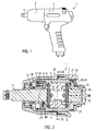
- Fig. 1 shows a side view of a pulse tool 1 with at least one drive unit 2 and a pulse unit 3. From the pulse unit 3 is a drive spindle 11, at a corresponding tool, for example, for a screw connection can be attached, such as a socket or the like.
- such a pulse tool is equipped with a pneumatic motor as a drive unit and can usually be operated both for tightening as well as for loosening a screw with clockwise and counterclockwise rotation.
- the pulse unit 3 of FIG. 1 is shown in a longitudinal section.
- the pulse unit 3 is arranged in a possibly multi-part housing 35.
- the pulse unit 3 has a rotor 4 which is drive-connected to the drive unit 2.
- slats 5, 6, 7 and 8 are mounted radially adjustable, see also Fig. 3.
- two diametrically opposite slats 5, 6 and 7, 8 are acted upon radially outwardly by corresponding compression springs 36.
- the free ends of the slats 5, 6, 7, 8 are in the region of sealing webs 37, see also Fig. 3, on an inner contour of a hydraulic cylinder 9, separating high and low pressure chambers 14, 15 from each other.
- Rotor, vanes, seal lands, and hydraulic rams cooperate in a conventional manner to produce pulse bursts at a particular pulse frequency.
- a pulse frequency is 20 to 30 Hz, as at such a pulse frequency economic screwing is guaranteed.
- the pulse unit 3 has at its left in Fig. 2 end a front plate 10 and a front cover 12.
- the front plate 10 is disposed between substantially rotor 4 and fins 5, 6, 7, 8 and the front cover 12.
- a Hydraulikfluidbehell sensible 13 is arranged in the front cover 12. This comprises at least one filling opening 24, which can be closed by a closing ball and a screw-in sealing pin or piston 38 and 39 after filling the pulse unit 3 with hydraulic fluid.
- the pulse unit is sealed on the side of the drive spindle 11, so that hydraulic fluid via sealing gaps between the front plate 10, front cover 12 and rotor 4 or fins 5, 6, 7, 8 is interchangeable between high pressure and low pressure chamber.
- the drive spindle 11 passes through both the front plate 10 and the front cover 12 and is for the arrangement of a corresponding tool from the pulse tool 1 before.
- the pulse unit 3 At its end facing the drive spindle 11 end 25, the pulse unit 3 has a fluid opening 27 in the hydraulic cylinder. Through these are the chambers 14, 15, see also Fig. 3, in the interior of the pulse unit 3 with a compensation chamber 26 with a corresponding equalization volume 28 in connection. This compensation chamber 26 is delimited by the hydraulic cylinder 9 and a compensating piston 29 which can be adjusted in the longitudinal direction 30 by turning.
- the balance piston 29 can be adjusted relative to the hydraulic cylinder 9 in Fig. 2 to the right, whereby the compensation chamber 26 receives a larger compensating volume 28.
- Certain rotational positions of the compensating piston 29 can be fixed by a pin as a fixing device 31, wherein, for example, four, six or more rotational positions in a revolution of the balance piston 29 are fixed accordingly.
- Fig. 3 is a section along the line III-III of Fig. 2 is shown.
- the arrangement of the high-pressure chambers 14 and low-pressure chambers 15 between two slats 5, 6, 7 and 8 can be seen here. These are mounted radially adjustable in the rotor 4 to the outside and pressurized spring.
- two high-pressure chambers 14 and two low-pressure chambers 15 are diametrically opposite each other, with the corresponding blades 5, 6, 7, 8 just in sealing contact with corresponding sealing webs 37.
- the direction of rotation of Fig. 3 is indicated by the reference numeral 34, wherein in this context, a clockwise rotation of the rotor or according to the drive spindle 11, see also Fig. 2, takes place.
- FIG. 4 shows a detailed representation of the pulse unit 3, in particular for the front panel 10 and the front cover 12. Visible are in the front plate bypass openings 16 and closing body 19 in the form of closing balls that close these bypass openings.
- the closing balls 19 are held between the front plate 10 and the front cover 12.
- the bypass openings are in communication with the corresponding chambers in the interior of the pulse unit 3.
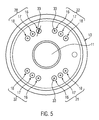
- Each bypass opening 16, 17, 18, see also Fig. 5, in the direction of the front cover 12 has a receiving seat 33 for the arrangement of the corresponding closing ball 19.
- the receiving seats 33 have the same cross-section for all bypass openings, so that each of the bypass openings 16, 17, 18 can be closed by a closing ball 19 with the same diameter.
- Each receiving seat 33 has, as a cross-section, substantially a conical part extending from a corresponding opening diameter 23 of the bypass openings and an adjoining substantially cylindrical part. With the conical part, the closing ball 19 is in sealing contact.
- the opening diameters 23 of the various bypass openings 16, 17, 18 are different, see in particular FIG. 5.
- bypass openings 16, 17, 18 are summarized in FIG. 5 to bypass opening groups 20, 32, 22 and 32.
- the bypass opening groups 20 and 21 communicate with the corresponding high-pressure chambers 14 of Fig. 3, with an analogous connection through the bypass opening groups 22 and 32 to high-pressure chambers in a reverse run, i. Anti-clockwise rotation of FIG. 3 takes place.
- each bypass opening group has three bypass openings 16, 17, 18.
- the arrangement of the bypass openings 16, 17, 18 takes place for the bypass opening groups 20 and 21 in the same and for the bypass opening groups 22 and 32 in the reverse direction.
- the various bypass openings 16, 17, 18 have decreasing opening diameters 23 in this order. That is, the two bypass port 16 has the largest and the bypass port 18 has the smallest opening diameter.
- bypass opening groups 20, 21 and 22, 32 are arranged diametrically opposite one another and assigned to the respective high-pressure chambers.
- unlocked bypass openings 16, 17, 18 penetrates hydraulic fluid into the low pressure chambers and flows primarily through center 40 of the front plate to the left side corresponding to Fig. 4 from the direction of the high pressure chambers, so that a hydraulic fluid exchange in this way takes place between the chambers and thus a faster driving over the sealing webs of the hydraulic cylinder is connected by the fins and thus a pulse frequency increase.
- a larger or smaller hydraulic fluid exchange takes place.
- a pulse frequency for setting a corresponding basic pulse frequency eight times by certain amounts can be varied.
- the corresponding basic pulse frequency is set before delivery of the pulse tool, in particular in the range of 20 Hz to 30 Hz.
- the corresponding opening diameters of the bypass openings 16, 17, 18 may be in the range of a few tenths of a millimeter. It is also possible to arrange fewer or more bypass openings for each bypass opening group, thereby resulting in correspondingly fewer or more adjustment possibilities for the basic pulse frequency.
- bypass openings and / or bypass opening groups for clockwise and counterclockwise rotation in order, for example, to design one impact direction more strongly than the other with other frequency capabilities.
- the arrangement of the closing body 19 in the corresponding receiving seats 33 takes place through the filling opening 24, wherein the front cover 12 according to the assignment of the filling opening 24 to each of the bypass openings 16, 17, 18 is rotatable.
- a corresponding front plate 10 can also be retrofitted for pulse tools already in use as a rule, see in particular FIGS. 2 and 4, wherein only an exchange of a corresponding previously used front plate with the front plate has to be made according to the invention.
Landscapes
- Engineering & Computer Science (AREA)
- Mechanical Engineering (AREA)
- Fluid-Pressure Circuits (AREA)
- Electrophonic Musical Instruments (AREA)
- Portable Nailing Machines And Staplers (AREA)
- Massaging Devices (AREA)
- Percussive Tools And Related Accessories (AREA)
- Shearing Machines (AREA)
- Valve Device For Special Equipments (AREA)
Priority Applications (5)
| Application Number | Priority Date | Filing Date | Title |
|---|---|---|---|
| EP06023567A EP1920888B1 (fr) | 2006-11-13 | 2006-11-13 | Outil rotatif à chocs et plaque antérieure pour celui ci |
| AT06023567T ATE506143T1 (de) | 2006-11-13 | 2006-11-13 | Impulswerkzeug und zugehörige vorderplatte |
| ES06023567T ES2365404T3 (es) | 2006-11-13 | 2006-11-13 | Herramienta de impulso y placa delantera correspondiente. |
| DE502006009359T DE502006009359D1 (de) | 2006-11-13 | 2006-11-13 | Impulswerkzeug und zugehörige Vorderplatte |
| US11/939,274 US7703546B2 (en) | 2006-11-13 | 2007-11-13 | Pulse tool and associated front plate |
Applications Claiming Priority (1)
| Application Number | Priority Date | Filing Date | Title |
|---|---|---|---|
| EP06023567A EP1920888B1 (fr) | 2006-11-13 | 2006-11-13 | Outil rotatif à chocs et plaque antérieure pour celui ci |
Publications (2)
| Publication Number | Publication Date |
|---|---|
| EP1920888A1 true EP1920888A1 (fr) | 2008-05-14 |
| EP1920888B1 EP1920888B1 (fr) | 2011-04-20 |
Family
ID=37852308
Family Applications (1)
| Application Number | Title | Priority Date | Filing Date |
|---|---|---|---|
| EP06023567A Not-in-force EP1920888B1 (fr) | 2006-11-13 | 2006-11-13 | Outil rotatif à chocs et plaque antérieure pour celui ci |
Country Status (5)
| Country | Link |
|---|---|
| US (1) | US7703546B2 (fr) |
| EP (1) | EP1920888B1 (fr) |
| AT (1) | ATE506143T1 (fr) |
| DE (1) | DE502006009359D1 (fr) |
| ES (1) | ES2365404T3 (fr) |
Cited By (2)
| Publication number | Priority date | Publication date | Assignee | Title |
|---|---|---|---|---|
| WO2011141205A1 (fr) * | 2010-05-12 | 2011-11-17 | Atlas Copco Tools Ab | Clé à choc comportant une unité d'impulsion hydraulique |
| WO2014198679A3 (fr) * | 2013-06-12 | 2015-02-05 | Atlas Copco Industrial Technique Ab | Procédé pour diagnostiquer un générateur d'impulsion de couple |
Families Citing this family (9)
| Publication number | Priority date | Publication date | Assignee | Title |
|---|---|---|---|---|
| EP2036679B1 (fr) * | 2007-09-11 | 2012-07-11 | Uryu Seisaku Ltd. | Dispositif de réglage de couple d'impact d'une clé dynamométrique hydraulique |
| JP5547004B2 (ja) * | 2010-09-07 | 2014-07-09 | 瓜生製作株式会社 | 油圧式トルクレンチの打撃トルク調節装置 |
| US9878435B2 (en) | 2013-06-12 | 2018-01-30 | Makita Corporation | Power rotary tool and impact power tool |
| TWM562747U (zh) | 2016-08-25 | 2018-07-01 | 米沃奇電子工具公司 | 衝擊工具 |
| JP6762572B2 (ja) * | 2017-08-31 | 2020-09-30 | 瓜生製作株式会社 | 油圧式トルクレンチの打撃トルク発生装置 |
| US12325112B2 (en) * | 2020-09-28 | 2025-06-10 | Milwaukee Electric Tool Corporation | Power tool with impulse assembly including a valve |
| SE544912C2 (en) * | 2021-04-28 | 2022-12-27 | Atlas Copco Ind Technique Ab | Pulse mechanism for Power Tool |
| US12447588B2 (en) | 2021-12-17 | 2025-10-21 | Black & Decker Inc. | Impact driver |
| SE2230372A1 (en) * | 2022-11-17 | 2024-01-09 | Atlas Copco Ind Technique Ab | Power tool comprising a hydraulic pulse unit |
Citations (4)
| Publication number | Priority date | Publication date | Assignee | Title |
|---|---|---|---|---|
| EP0187129A2 (fr) * | 1984-12-21 | 1986-07-09 | Atlas Copco Aktiebolag | Outil hydraulique rotatif à chocs |
| EP0465450A2 (fr) * | 1990-07-03 | 1992-01-08 | Atlas Copco Tools Ab, Stockholm | Générateur hydraulique d'impulsion de couple |
| US5611404A (en) | 1995-09-28 | 1997-03-18 | Gpx Corp. | Hydraulic impulse tool with enhanced fluid seal |
| DE20210453U1 (de) | 2002-07-05 | 2003-11-13 | Cooper Power Tools GmbH & Co., 73463 Westhausen | Impulseinheit |
Family Cites Families (13)
| Publication number | Priority date | Publication date | Assignee | Title |
|---|---|---|---|---|
| JPH0223964U (fr) * | 1988-07-29 | 1990-02-16 | ||
| US4836296A (en) * | 1988-08-22 | 1989-06-06 | Dresser Industries, Inc. | Fluid pressure impulse nut runner |
| EP0398655B1 (fr) * | 1989-05-15 | 1995-09-27 | Uryu Seisaku, Ltd. | Moyen de détection de pression pour des clefs à couple contrôlé |
| US6082986A (en) * | 1998-08-19 | 2000-07-04 | Cooper Technologies | Reversible double-throw air motor |
| JP3401544B2 (ja) * | 1998-10-15 | 2003-04-28 | 不二空機株式会社 | 油圧式パルスレンチの締付制御装置 |
| TW417558U (en) * | 1999-03-09 | 2001-01-01 | Best Power Tools Co Ltd | Cylinder device of a pneumatic tool |
| US6241500B1 (en) * | 2000-03-23 | 2001-06-05 | Cooper Brands, Inc. | Double-throw air motor with reverse feature |
| JP3615125B2 (ja) * | 2000-03-30 | 2005-01-26 | 株式会社マキタ | オイルユニット及び電動工具 |
| EP1345737A2 (fr) * | 2000-09-08 | 2003-09-24 | S.P. Air Kabusiki Kaisha | Outil rotatif pneumatique |
| EP1501657B1 (fr) * | 2002-05-09 | 2013-07-10 | Snap-on Incorporated | Mecanisme d'arret automatique d'air destine a un outil d'application de couple pour pneumatique |
| US6863134B2 (en) * | 2003-03-07 | 2005-03-08 | Ingersoll-Rand Company | Rotary tool |
| ES2335911T3 (es) * | 2006-11-13 | 2010-04-06 | COOPER POWER TOOLS GMBH & CO. | Herramienta de impulso. |
| ATE452731T1 (de) * | 2006-11-13 | 2010-01-15 | Cooper Power Tools Gmbh & Co | Werkzeug mit einem hydraulikschlagwerk |
-
2006
- 2006-11-13 ES ES06023567T patent/ES2365404T3/es active Active
- 2006-11-13 DE DE502006009359T patent/DE502006009359D1/de active Active
- 2006-11-13 AT AT06023567T patent/ATE506143T1/de active
- 2006-11-13 EP EP06023567A patent/EP1920888B1/fr not_active Not-in-force
-
2007
- 2007-11-13 US US11/939,274 patent/US7703546B2/en not_active Expired - Fee Related
Patent Citations (4)
| Publication number | Priority date | Publication date | Assignee | Title |
|---|---|---|---|---|
| EP0187129A2 (fr) * | 1984-12-21 | 1986-07-09 | Atlas Copco Aktiebolag | Outil hydraulique rotatif à chocs |
| EP0465450A2 (fr) * | 1990-07-03 | 1992-01-08 | Atlas Copco Tools Ab, Stockholm | Générateur hydraulique d'impulsion de couple |
| US5611404A (en) | 1995-09-28 | 1997-03-18 | Gpx Corp. | Hydraulic impulse tool with enhanced fluid seal |
| DE20210453U1 (de) | 2002-07-05 | 2003-11-13 | Cooper Power Tools GmbH & Co., 73463 Westhausen | Impulseinheit |
Cited By (7)
| Publication number | Priority date | Publication date | Assignee | Title |
|---|---|---|---|---|
| WO2011141205A1 (fr) * | 2010-05-12 | 2011-11-17 | Atlas Copco Tools Ab | Clé à choc comportant une unité d'impulsion hydraulique |
| CN102905851A (zh) * | 2010-05-12 | 2013-01-30 | 阿特拉斯·科普柯工业技术公司 | 具有液压脉冲单元的动力扳手 |
| CN102905851B (zh) * | 2010-05-12 | 2015-02-18 | 阿特拉斯·科普柯工业技术公司 | 具有液压脉冲单元的动力扳手 |
| US9259826B2 (en) | 2010-05-12 | 2016-02-16 | Atlas Copco Industrial Technique Ab | Power wrench with hydraulic pulse unit |
| WO2014198679A3 (fr) * | 2013-06-12 | 2015-02-05 | Atlas Copco Industrial Technique Ab | Procédé pour diagnostiquer un générateur d'impulsion de couple |
| CN105682858A (zh) * | 2013-06-12 | 2016-06-15 | 阿特拉斯·科普柯工业技术公司 | 用于诊断转矩脉冲发生器的方法 |
| US9983044B2 (en) | 2013-06-12 | 2018-05-29 | Atlas Copco Industrial Technique Ab | Method for diagnosing a torque impulse generator |
Also Published As
| Publication number | Publication date |
|---|---|
| US7703546B2 (en) | 2010-04-27 |
| EP1920888B1 (fr) | 2011-04-20 |
| ES2365404T3 (es) | 2011-10-04 |
| DE502006009359D1 (de) | 2011-06-01 |
| US20090008117A1 (en) | 2009-01-08 |
| ATE506143T1 (de) | 2011-05-15 |
Similar Documents
| Publication | Publication Date | Title |
|---|---|---|
| DE2503247A1 (de) | Stossdaempfer | |
| EP1920888B1 (fr) | Outil rotatif à chocs et plaque antérieure pour celui ci | |
| DE1815163A1 (de) | Zweistufiger Kompressor | |
| DE102013102031B4 (de) | Aus wenigstens zwei Teilen gebildete Schraubenspindelpumpe | |
| DE69601884T2 (de) | Hydraulischer Drehschlagmechanismus | |
| DE2735677B2 (de) | Drehschieberventil | |
| DE2504892A1 (de) | Integrierte kraftlenkvorrichtung | |
| DE1503100A1 (de) | Impulswerkzeug | |
| EP2103814A2 (fr) | Actionneur rotatif fluidique | |
| DE3872759T2 (de) | Hydraulischer drehmomentimpuls-erzeuger. | |
| DE102014101240A1 (de) | Brecher mit einstellbarem Exzenter | |
| DE4443860A1 (de) | Kraftstoffeinspritzpumpe für Brennkraftmaschinen | |
| DE2721705A1 (de) | Druckausgeglichenes ventil mit druckfuehleinrichtung | |
| DE19631625A1 (de) | Hydraulikventil mit Druckbegrenzungs- und Einspeisefunktion | |
| DE1553059A1 (de) | Hydraulische Rotationspumpe oder -motor | |
| DE1961843U (de) | Ventil, das gleichzeitig als sperr-, regel- und rueckschlagventil fuer fluessigkeiten wirkt. | |
| DE69911386T2 (de) | Einstellbare spiegelplatte für eine hydraulische pumpe oder motor | |
| DE1923759A1 (de) | Steuervorrichtung fuer einen Druckmittelmotor sowie Zufuehrungs- und Steuerventile dafuer | |
| DE4420694C2 (de) | Dosierpumpe | |
| CH680753A5 (fr) | ||
| EP0161237B1 (fr) | Distributeur à commande hydraulique | |
| DE102022118308B4 (de) | Druckregelventil | |
| DE112014001565T5 (de) | Servolenkvorrichtung | |
| DE4018084C1 (fr) | ||
| DE102007053936B4 (de) | Hydraulischer Schwenkmotor |
Legal Events
| Date | Code | Title | Description |
|---|---|---|---|
| PUAI | Public reference made under article 153(3) epc to a published international application that has entered the european phase |
Free format text: ORIGINAL CODE: 0009012 |
|
| AK | Designated contracting states |
Kind code of ref document: A1 Designated state(s): AT BE BG CH CY CZ DE DK EE ES FI FR GB GR HU IE IS IT LI LT LU LV MC NL PL PT RO SE SI SK TR |
|
| AX | Request for extension of the european patent |
Extension state: AL BA HR MK RS |
|
| 17P | Request for examination filed |
Effective date: 20081113 |
|
| 17Q | First examination report despatched |
Effective date: 20081222 |
|
| AKX | Designation fees paid |
Designated state(s): AT BE BG CH CY CZ DE DK EE ES FI FR GB GR HU IE IS IT LI LT LU LV MC NL PL PT RO SE SI SK TR |
|
| GRAP | Despatch of communication of intention to grant a patent |
Free format text: ORIGINAL CODE: EPIDOSNIGR1 |
|
| GRAS | Grant fee paid |
Free format text: ORIGINAL CODE: EPIDOSNIGR3 |
|
| GRAA | (expected) grant |
Free format text: ORIGINAL CODE: 0009210 |
|
| AK | Designated contracting states |
Kind code of ref document: B1 Designated state(s): AT BE BG CH CY CZ DE DK EE ES FI FR GB GR HU IE IS IT LI LT LU LV MC NL PL PT RO SE SI SK TR |
|
| REG | Reference to a national code |
Ref country code: GB Ref legal event code: FG4D Free format text: NOT ENGLISH |
|
| REG | Reference to a national code |
Ref country code: CH Ref legal event code: EP |
|
| REG | Reference to a national code |
Ref country code: IE Ref legal event code: FG4D Free format text: LANGUAGE OF EP DOCUMENT: GERMAN |
|
| REF | Corresponds to: |
Ref document number: 502006009359 Country of ref document: DE Date of ref document: 20110601 Kind code of ref document: P |
|
| REG | Reference to a national code |
Ref country code: DE Ref legal event code: R096 Ref document number: 502006009359 Country of ref document: DE Effective date: 20110601 |
|
| REG | Reference to a national code |
Ref country code: SE Ref legal event code: TRGR |
|
| REG | Reference to a national code |
Ref country code: NL Ref legal event code: VDEP Effective date: 20110420 |
|
| LTIE | Lt: invalidation of european patent or patent extension |
Effective date: 20110420 |
|
| REG | Reference to a national code |
Ref country code: ES Ref legal event code: FG2A Ref document number: 2365404 Country of ref document: ES Kind code of ref document: T3 Effective date: 20111004 |
|
| PG25 | Lapsed in a contracting state [announced via postgrant information from national office to epo] |
Ref country code: PT Free format text: LAPSE BECAUSE OF FAILURE TO SUBMIT A TRANSLATION OF THE DESCRIPTION OR TO PAY THE FEE WITHIN THE PRESCRIBED TIME-LIMIT Effective date: 20110822 Ref country code: LT Free format text: LAPSE BECAUSE OF FAILURE TO SUBMIT A TRANSLATION OF THE DESCRIPTION OR TO PAY THE FEE WITHIN THE PRESCRIBED TIME-LIMIT Effective date: 20110420 |
|
| REG | Reference to a national code |
Ref country code: IE Ref legal event code: FD4D |
|
| REG | Reference to a national code |
Ref country code: HU Ref legal event code: AG4A Ref document number: E011515 Country of ref document: HU |
|
| PG25 | Lapsed in a contracting state [announced via postgrant information from national office to epo] |
Ref country code: GR Free format text: LAPSE BECAUSE OF FAILURE TO SUBMIT A TRANSLATION OF THE DESCRIPTION OR TO PAY THE FEE WITHIN THE PRESCRIBED TIME-LIMIT Effective date: 20110721 Ref country code: FI Free format text: LAPSE BECAUSE OF FAILURE TO SUBMIT A TRANSLATION OF THE DESCRIPTION OR TO PAY THE FEE WITHIN THE PRESCRIBED TIME-LIMIT Effective date: 20110420 Ref country code: LV Free format text: LAPSE BECAUSE OF FAILURE TO SUBMIT A TRANSLATION OF THE DESCRIPTION OR TO PAY THE FEE WITHIN THE PRESCRIBED TIME-LIMIT Effective date: 20110420 Ref country code: CY Free format text: LAPSE BECAUSE OF FAILURE TO SUBMIT A TRANSLATION OF THE DESCRIPTION OR TO PAY THE FEE WITHIN THE PRESCRIBED TIME-LIMIT Effective date: 20110420 Ref country code: IS Free format text: LAPSE BECAUSE OF FAILURE TO SUBMIT A TRANSLATION OF THE DESCRIPTION OR TO PAY THE FEE WITHIN THE PRESCRIBED TIME-LIMIT Effective date: 20110820 Ref country code: SI Free format text: LAPSE BECAUSE OF FAILURE TO SUBMIT A TRANSLATION OF THE DESCRIPTION OR TO PAY THE FEE WITHIN THE PRESCRIBED TIME-LIMIT Effective date: 20110420 |
|
| PG25 | Lapsed in a contracting state [announced via postgrant information from national office to epo] |
Ref country code: NL Free format text: LAPSE BECAUSE OF FAILURE TO SUBMIT A TRANSLATION OF THE DESCRIPTION OR TO PAY THE FEE WITHIN THE PRESCRIBED TIME-LIMIT Effective date: 20110420 |
|
| PG25 | Lapsed in a contracting state [announced via postgrant information from national office to epo] |
Ref country code: EE Free format text: LAPSE BECAUSE OF FAILURE TO SUBMIT A TRANSLATION OF THE DESCRIPTION OR TO PAY THE FEE WITHIN THE PRESCRIBED TIME-LIMIT Effective date: 20110420 Ref country code: IE Free format text: LAPSE BECAUSE OF FAILURE TO SUBMIT A TRANSLATION OF THE DESCRIPTION OR TO PAY THE FEE WITHIN THE PRESCRIBED TIME-LIMIT Effective date: 20110420 Ref country code: CZ Free format text: LAPSE BECAUSE OF FAILURE TO SUBMIT A TRANSLATION OF THE DESCRIPTION OR TO PAY THE FEE WITHIN THE PRESCRIBED TIME-LIMIT Effective date: 20110420 |
|
| PLBE | No opposition filed within time limit |
Free format text: ORIGINAL CODE: 0009261 |
|
| STAA | Information on the status of an ep patent application or granted ep patent |
Free format text: STATUS: NO OPPOSITION FILED WITHIN TIME LIMIT |
|
| PG25 | Lapsed in a contracting state [announced via postgrant information from national office to epo] |
Ref country code: SK Free format text: LAPSE BECAUSE OF FAILURE TO SUBMIT A TRANSLATION OF THE DESCRIPTION OR TO PAY THE FEE WITHIN THE PRESCRIBED TIME-LIMIT Effective date: 20110420 Ref country code: DK Free format text: LAPSE BECAUSE OF FAILURE TO SUBMIT A TRANSLATION OF THE DESCRIPTION OR TO PAY THE FEE WITHIN THE PRESCRIBED TIME-LIMIT Effective date: 20110420 Ref country code: RO Free format text: LAPSE BECAUSE OF FAILURE TO SUBMIT A TRANSLATION OF THE DESCRIPTION OR TO PAY THE FEE WITHIN THE PRESCRIBED TIME-LIMIT Effective date: 20110420 Ref country code: PL Free format text: LAPSE BECAUSE OF FAILURE TO SUBMIT A TRANSLATION OF THE DESCRIPTION OR TO PAY THE FEE WITHIN THE PRESCRIBED TIME-LIMIT Effective date: 20110420 |
|
| 26N | No opposition filed |
Effective date: 20120123 |
|
| REG | Reference to a national code |
Ref country code: DE Ref legal event code: R097 Ref document number: 502006009359 Country of ref document: DE Effective date: 20120123 |
|
| BERE | Be: lapsed |
Owner name: COOPER POWER TOOLS G.M.B.H. & CO. Effective date: 20111130 |
|
| PG25 | Lapsed in a contracting state [announced via postgrant information from national office to epo] |
Ref country code: MC Free format text: LAPSE BECAUSE OF NON-PAYMENT OF DUE FEES Effective date: 20111130 |
|
| REG | Reference to a national code |
Ref country code: CH Ref legal event code: PL |
|
| PG25 | Lapsed in a contracting state [announced via postgrant information from national office to epo] |
Ref country code: CH Free format text: LAPSE BECAUSE OF NON-PAYMENT OF DUE FEES Effective date: 20111130 Ref country code: LI Free format text: LAPSE BECAUSE OF NON-PAYMENT OF DUE FEES Effective date: 20111130 |
|
| PG25 | Lapsed in a contracting state [announced via postgrant information from national office to epo] |
Ref country code: BE Free format text: LAPSE BECAUSE OF NON-PAYMENT OF DUE FEES Effective date: 20111130 |
|
| REG | Reference to a national code |
Ref country code: AT Ref legal event code: MM01 Ref document number: 506143 Country of ref document: AT Kind code of ref document: T Effective date: 20111113 |
|
| PG25 | Lapsed in a contracting state [announced via postgrant information from national office to epo] |
Ref country code: AT Free format text: LAPSE BECAUSE OF NON-PAYMENT OF DUE FEES Effective date: 20111113 |
|
| PGFP | Annual fee paid to national office [announced via postgrant information from national office to epo] |
Ref country code: HU Payment date: 20121026 Year of fee payment: 7 |
|
| PGFP | Annual fee paid to national office [announced via postgrant information from national office to epo] |
Ref country code: GB Payment date: 20121025 Year of fee payment: 7 Ref country code: IT Payment date: 20121120 Year of fee payment: 7 |
|
| PG25 | Lapsed in a contracting state [announced via postgrant information from national office to epo] |
Ref country code: LU Free format text: LAPSE BECAUSE OF NON-PAYMENT OF DUE FEES Effective date: 20111113 |
|
| PG25 | Lapsed in a contracting state [announced via postgrant information from national office to epo] |
Ref country code: BG Free format text: LAPSE BECAUSE OF FAILURE TO SUBMIT A TRANSLATION OF THE DESCRIPTION OR TO PAY THE FEE WITHIN THE PRESCRIBED TIME-LIMIT Effective date: 20110720 |
|
| PG25 | Lapsed in a contracting state [announced via postgrant information from national office to epo] |
Ref country code: TR Free format text: LAPSE BECAUSE OF FAILURE TO SUBMIT A TRANSLATION OF THE DESCRIPTION OR TO PAY THE FEE WITHIN THE PRESCRIBED TIME-LIMIT Effective date: 20110420 |
|
| PGFP | Annual fee paid to national office [announced via postgrant information from national office to epo] |
Ref country code: SE Payment date: 20131120 Year of fee payment: 8 Ref country code: FR Payment date: 20131031 Year of fee payment: 8 Ref country code: DE Payment date: 20131120 Year of fee payment: 8 |
|
| PGFP | Annual fee paid to national office [announced via postgrant information from national office to epo] |
Ref country code: ES Payment date: 20131125 Year of fee payment: 8 |
|
| GBPC | Gb: european patent ceased through non-payment of renewal fee |
Effective date: 20131113 |
|
| PG25 | Lapsed in a contracting state [announced via postgrant information from national office to epo] |
Ref country code: IT Free format text: LAPSE BECAUSE OF NON-PAYMENT OF DUE FEES Effective date: 20131113 |
|
| PG25 | Lapsed in a contracting state [announced via postgrant information from national office to epo] |
Ref country code: HU Free format text: LAPSE BECAUSE OF NON-PAYMENT OF DUE FEES Effective date: 20131114 |
|
| PG25 | Lapsed in a contracting state [announced via postgrant information from national office to epo] |
Ref country code: GB Free format text: LAPSE BECAUSE OF NON-PAYMENT OF DUE FEES Effective date: 20131113 |
|
| REG | Reference to a national code |
Ref country code: DE Ref legal event code: R119 Ref document number: 502006009359 Country of ref document: DE |
|
| REG | Reference to a national code |
Ref country code: SE Ref legal event code: EUG |
|
| PG25 | Lapsed in a contracting state [announced via postgrant information from national office to epo] |
Ref country code: SE Free format text: LAPSE BECAUSE OF NON-PAYMENT OF DUE FEES Effective date: 20141114 |
|
| REG | Reference to a national code |
Ref country code: FR Ref legal event code: ST Effective date: 20150731 |
|
| PG25 | Lapsed in a contracting state [announced via postgrant information from national office to epo] |
Ref country code: DE Free format text: LAPSE BECAUSE OF NON-PAYMENT OF DUE FEES Effective date: 20150602 |
|
| PG25 | Lapsed in a contracting state [announced via postgrant information from national office to epo] |
Ref country code: FR Free format text: LAPSE BECAUSE OF NON-PAYMENT OF DUE FEES Effective date: 20141201 |
|
| REG | Reference to a national code |
Ref country code: ES Ref legal event code: FD2A Effective date: 20151229 |
|
| PG25 | Lapsed in a contracting state [announced via postgrant information from national office to epo] |
Ref country code: ES Free format text: LAPSE BECAUSE OF NON-PAYMENT OF DUE FEES Effective date: 20141114 |