EP1920998B1 - Carrosserie de véhicule automobile et procédé de montage de celle-ci - Google Patents
Carrosserie de véhicule automobile et procédé de montage de celle-ci Download PDFInfo
- Publication number
- EP1920998B1 EP1920998B1 EP07021163A EP07021163A EP1920998B1 EP 1920998 B1 EP1920998 B1 EP 1920998B1 EP 07021163 A EP07021163 A EP 07021163A EP 07021163 A EP07021163 A EP 07021163A EP 1920998 B1 EP1920998 B1 EP 1920998B1
- Authority
- EP
- European Patent Office
- Prior art keywords
- mudguard
- support
- vehicle body
- fender
- motor
- Prior art date
- Legal status (The legal status is an assumption and is not a legal conclusion. Google has not performed a legal analysis and makes no representation as to the accuracy of the status listed.)
- Not-in-force
Links
- 238000000034 method Methods 0.000 title claims abstract description 11
- 239000003973 paint Substances 0.000 claims abstract 5
- 239000000463 material Substances 0.000 claims abstract 4
- 238000010422 painting Methods 0.000 claims description 5
- 238000006073 displacement reaction Methods 0.000 claims description 2
- 239000012815 thermoplastic material Substances 0.000 claims description 2
- FGUUSXIOTUKUDN-IBGZPJMESA-N C1(=CC=CC=C1)N1C2=C(NC([C@H](C1)NC=1OC(=NN=1)C1=CC=CC=C1)=O)C=CC=C2 Chemical compound C1(=CC=CC=C1)N1C2=C(NC([C@H](C1)NC=1OC(=NN=1)C1=CC=CC=C1)=O)C=CC=C2 FGUUSXIOTUKUDN-IBGZPJMESA-N 0.000 claims 2
- 238000003780 insertion Methods 0.000 claims 1
- 230000037431 insertion Effects 0.000 claims 1
- 239000002184 metal Substances 0.000 description 5
- 239000004033 plastic Substances 0.000 description 4
- FGRBYDKOBBBPOI-UHFFFAOYSA-N 10,10-dioxo-2-[4-(N-phenylanilino)phenyl]thioxanthen-9-one Chemical compound O=C1c2ccccc2S(=O)(=O)c2ccc(cc12)-c1ccc(cc1)N(c1ccccc1)c1ccccc1 FGRBYDKOBBBPOI-UHFFFAOYSA-N 0.000 description 2
- 239000004743 Polypropylene Substances 0.000 description 2
- 239000012634 fragment Substances 0.000 description 2
- 238000009434 installation Methods 0.000 description 2
- 238000004519 manufacturing process Methods 0.000 description 2
- 238000007591 painting process Methods 0.000 description 2
- -1 polypropylene Polymers 0.000 description 2
- 229920001155 polypropylene Polymers 0.000 description 2
- 238000010521 absorption reaction Methods 0.000 description 1
- 238000004873 anchoring Methods 0.000 description 1
- 239000000969 carrier Substances 0.000 description 1
- 238000010276 construction Methods 0.000 description 1
- 210000003195 fascia Anatomy 0.000 description 1
- 239000000446 fuel Substances 0.000 description 1
- 238000002347 injection Methods 0.000 description 1
- 239000007924 injection Substances 0.000 description 1
- 230000001681 protective effect Effects 0.000 description 1
- 230000000284 resting effect Effects 0.000 description 1
- 239000002904 solvent Substances 0.000 description 1
Images



Classifications
-
- B—PERFORMING OPERATIONS; TRANSPORTING
- B62—LAND VEHICLES FOR TRAVELLING OTHERWISE THAN ON RAILS
- B62D—MOTOR VEHICLES; TRAILERS
- B62D25/00—Superstructure or monocoque structure sub-units; Parts or details thereof not otherwise provided for
- B62D25/08—Front or rear portions
- B62D25/16—Mud-guards or wings; Wheel cover panels
- B62D25/161—Mud-guards made of non-conventional material, e.g. rubber, plastics
-
- B—PERFORMING OPERATIONS; TRANSPORTING
- B60—VEHICLES IN GENERAL
- B60R—VEHICLES, VEHICLE FITTINGS, OR VEHICLE PARTS, NOT OTHERWISE PROVIDED FOR
- B60R21/00—Arrangements or fittings on vehicles for protecting or preventing injuries to occupants or pedestrians in case of accidents or other traffic risks
- B60R21/34—Protecting non-occupants of a vehicle, e.g. pedestrians
-
- B—PERFORMING OPERATIONS; TRANSPORTING
- B62—LAND VEHICLES FOR TRAVELLING OTHERWISE THAN ON RAILS
- B62D—MOTOR VEHICLES; TRAILERS
- B62D25/00—Superstructure or monocoque structure sub-units; Parts or details thereof not otherwise provided for
- B62D25/08—Front or rear portions
- B62D25/16—Mud-guards or wings; Wheel cover panels
- B62D25/163—Mounting devices
-
- B—PERFORMING OPERATIONS; TRANSPORTING
- B62—LAND VEHICLES FOR TRAVELLING OTHERWISE THAN ON RAILS
- B62D—MOTOR VEHICLES; TRAILERS
- B62D27/00—Connections between superstructure or understructure sub-units
- B62D27/06—Connections between superstructure or understructure sub-units readily releasable
- B62D27/065—Connections between superstructure or understructure sub-units readily releasable using screwthread
-
- B—PERFORMING OPERATIONS; TRANSPORTING
- B60—VEHICLES IN GENERAL
- B60R—VEHICLES, VEHICLE FITTINGS, OR VEHICLE PARTS, NOT OTHERWISE PROVIDED FOR
- B60R21/00—Arrangements or fittings on vehicles for protecting or preventing injuries to occupants or pedestrians in case of accidents or other traffic risks
- B60R21/34—Protecting non-occupants of a vehicle, e.g. pedestrians
- B60R2021/343—Protecting non-occupants of a vehicle, e.g. pedestrians using deformable body panel, bodywork or components
Definitions
- the present invention relates to a motor vehicle body and a method of assembling the same.
- the load-bearing parts of the shell and the parts of the outer skin such as front and tailgate, doors, fenders are made of metal and are assembled before the body is painted as a whole.
- the outer skin made of plastic In order to reduce the weight of a vehicle and thus its fuel consumption, it is interesting in itself to manufacture parts of the outer skin made of plastic.
- the problem arises that made of inexpensive plastic outer skin parts are usually not suitable to be painted together with the metal parts of the body in one operation, either because they are not against the occurring in the painting process high temperatures in the order of 200 ° C are resistant because they are incompatible with solvents used, or for other reasons.
- Out FR 2 815 090 A1 is a motor vehicle body with a Lackierbe treatingn shell and at least one fender, which is held on the shell by a fender carrier and fastened to the fender carrier known.
- WO 98/18670 A1 discloses a motor vehicle body composed of a plurality of separately painted components.
- EP 1 403 175 A2 teaches a fender assembly on motor vehicles, in which a fender bank is firmly connected on the one hand with a supporting part of the body and on the other hand with a fender.
- EP 1 398 249 A1 describes the construction of a motor vehicle body with a frame, a fender and a carrier connecting the frame and the fender, whose position on the frame by means of in Oversized holes of the carrier engaging screws is customizable.
- the object of the present invention is to provide a motor vehicle body and a mounting method therefor, which make it possible in an economical way to obstruct fenders, which are not suitable for painting together with the body shell of the body.
- the object is achieved by a motor vehicle body having the features of claim 1 and by a method having the features of claim 11.
- the fender carrier expediently comprises a wheelhouse of the vehicle bridging strap and two extending from the bracket from both sides of the wheel arch downwards extending arms.
- the body according to the invention enables a mounting method in which the fender carrier is first aligned and fastened to the provided shell and, after the shell has been painted together with the fender carrier, the fender is mounted on a defined by the fender carrier body.
- the assembly of the mudguard carrier as conventionally that of the mudguard itself can be such that a desired gap width between the not yet mounted, but defined in its position by the fender carrier fender and adjacent parts of the outer skin is ensured.
- a hood can be correctly mounted and adjusted, which is flanked later by the fenders worn by the fender carriers.
- fenders and fender carrier are designed so that the fender can be fastened to the fender carrier only in a single position.
- this single position can be easily found, the fender carrier and the fender preferably on cooperating guide surfaces, which in contact with each other, a movement of the still unfastened fender against the fender carrier in two degrees of freedom, said by said movement said single position is reachable.
- one of the guide surfaces is conveniently a flat surface that intersects a second planar surface.
- the line in which the two flat surfaces intersect forms on the one hand an easy-to-find fiducial for the positioning of the fender and, on the other hand, provides a preferred direction of movement in which the fender can be moved to the single position.
- the fender carrier and the fender preferably have at least one opening and the other has a projection which is positively inserted into the opening in the fully assembled vehicle body.
- the fender carrier is preferably attached to the shell by screws, which prevail extending substantially in the longitudinal direction of the body extending slots of the fender carrier. These slots create a play of the fender carrier in the vehicle longitudinal direction, in particular an orientation of the fender in relation to an adjacent door. Further, by the screws passing through the slots with a play in the transverse direction of the body, the possibility is created to rotate the fuselage support during alignment or to move in the transverse direction.
- a protective measure in the event of a collision with a pedestrian may be provided that an upper portion of the fender is supported on the fender carrier via at least one vertically and / or resilient in the direction of travel buffer element.
- the fender may be part of a fender module held by the fender carrier which further comprises at least one headlight or a headlight socket.
- a headlight or a headlight socket can be integrated into the fender carrier itself.
- the fender may be made of a thermoplastic material, in particular of polypropylene.
- fender carrier 1 comprises an elongated bracket 2, from the ends of each arm 3 and 4 protrudes.
- the downwardly curved arms 3, 4 each extend into an angled flap 5.
- Long holes 6 are distributed over the length of the bracket 2, which are used for fastening the fender carrier 1 on a fender bank 7 of a body shell by means of screws 8.
- parallel slots 6 are formed in the tabs 5, to attach them to the shell, for example, adjacent to the front end of a longitudinal member 9 or on a sill 10.
- the bracket 2 and the arms 3, 4 are injection molded here in one piece from a heat-resistant plastic. To stiffen the bracket 2 and the arms 3 are reinforced at their edges by circumferential ribs 11. Alternatively, the bracket 2 and the arms 3, 4 could also be made of metal.
- the bracket 2 carries on its upper side in each case a buffer element 12, here in the form of a sleeve of hexagonal cross-section with an upper side 13, which is provided in the Fig. 1, 2
- the strength of the buffer elements 12 is dimensioned so that they are substantially dimensionally stable under the loads occurring during normal use of a motor vehicle, but that they are flattened with energy absorption, if in a crash, a pedestrian strikes the fender from above , Since the longitudinal axis of the sleeves 12 is oriented substantially in the transverse direction of the vehicle body, the sleeves 12 are also able to yield to a force acting in a collision from the front while absorbing energy.
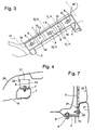
- Fig. 3 shows a plan view of the fender carrier 1 and the fender bank 7, where it is anchored by the screws 8.
- On the upper sides 13 of the buffer elements 12 are each two openings, an elongated opening 14 and a round opening 15 can be seen. These openings define the position of the fender with respect to the fender carrier 1 in a manner to be described in more detail later. Since the fender carrier 1 unambiguously defines the position of the fender, it can be ensured by aligning the fender carrier 1 with respect to adjacent body parts that the fender carrier 1 when mounted later, it will be correctly positioned with respect to these body panels.
- the fender carrier 1 is aligned so that there is a desired gap width between this and the door during the later assembly of the fender. Since the screws 8 enforce the slots 6 with a game in the transverse direction, it is possible to move the fender carrier 1 in dimensions transversely and to rotate about a vertical axis.
- a Fig. 3 partly as dot-dashed Outline indicated hoods 17 are two opposing fender carrier 1 aligned so that in Fig. 3 With 18 designated corners of their bracket 2 form exactly a symmetrical trapezoidal of the hood gauge 17 predetermined shape. The fixed in the position thus obtained fender carrier 1 then serve as a reference for the assembly of a hood, not shown.
- Fig. 4 shows a schematic partial section through the fully assembled body along in Fig. 3 with IV designated level.
- the section extends through a slot 6 and shows the screw 8 received therein, which fixes the bracket 2 to the fender bank 7.
- Below the fender bank 7, a wall 19 of a wheel well can be seen.
- the polypropylene molded fender 20 has a horizontal edge strip 21 resting on the buffer members 12.
- the edge strip 21 is bounded by a vertical stop edge 22. This stop edge 22 may extend in sections or preferably continuously along the entire edge strip 21.
- the edge strip 21 obscures the view of a fitter on the fender carrier 1, which in itself makes the exact placement of the fender 20 difficult.
- Fig. 5 illustrates that one too Fig. 4 parallel section along the in Fig. 3 with V designated level shows.
- Fig. 7 shows a section through the lower end of the front arm 3 of the fender carrier 1 and its surroundings on the fully assembled vehicle body.
- a screw 8 which passes through the slot 6 of the tab 5, fixes the lower end of the arm 3 to a wall of the wheel arch XX or other suitable part of the body shell.
- a lower edge region of the fender 20 lies, hidden by a bumper cover 27, at the lower end of the arm 3. Like the edge strip 21, this lower edge region carries a latching projection 24 which engages in a corresponding opening of the arm 3 and thereby defines a position of the fender 20 in which an adjacent opening 15 of the arm 3 is aligned with an opening of the fender 20. so that the fender can be fastened by a clip 26 inserted through both openings.
- Fig. 8 shows in one too Fig. 7 a screw 8, which passes through the slot 6 of the tab 5, fixes the lower end of the arm 4 to a wall of the sill 10 (this item number is missing in the picture) or another suitable part of the body shell ,
- the fender 20 is angled at its lower edge and extends over the tab 5. It is invisible to a viewer standing next to the vehicle by a clip 26 which is inserted from below into aligned openings of the edge region and the flap 5.
- the fender carrier 1 is for the sole purpose of attaching the plate-like fender 20 to the vehicle body.
- a fender may also be pre-assembled with other components of the vehicle, such as in particular a headlight or a headlight socket, to a module which is placed and fastened as a unit to the fender carrier.
- other components of the vehicle such as in particular a headlight or a headlight socket
- Fig. 9 one too Fig. 2 analogous view, in which a socket 28 is integrated for a headlight in the fender carrier 1.
Landscapes
- Engineering & Computer Science (AREA)
- Mechanical Engineering (AREA)
- Chemical & Material Sciences (AREA)
- Combustion & Propulsion (AREA)
- Transportation (AREA)
- Body Structure For Vehicles (AREA)
- Automobile Manufacture Line, Endless Track Vehicle, Trailer (AREA)
Claims (15)
- Carrosserie de véhicule à moteur avec une caisse brute résistante à la peinture et au moins une aile (20) faite d'un matériau ne pouvant pas être peint en même temps que la caisse brute, qui est retenu sur la caisse brute par un support d'aile (1) fait d'un matériau résistant à la peinture et orientable par rapport à la caisse brute et qui peut être fixé dans une seule position sur le support d'aile (1), dans laquelle le support d'aile (1) comporte un étrier (2) surmontant un logement de roue (19) et deux bras (3, 4) s'écartant de l'étrier (2) vers le bas de part et d'autre du logement de roue (19).
- Carrosserie de véhicule à moteur selon la revendication 1, caractérisée en ce que le support d'aile (1) et l'aile (20) présentent des surfaces de guidage (13 ; 21, 22) coopérant entre elles qui guident, en contact l'une avec l'autre, un mouvement de l'aile (20) non fixée vers le support d'aile (1) dans deux degrés de liberté qui permettent d'atteindre la position unique.
- Carrosserie de véhicule à moteur selon la revendication 2, caractérisée en ce que l'une des surfaces de guidage (21 ; 22) est une surface plane qui croise une deuxième surface plane (22 ; 21).
- Carrosserie de véhicule à moteur selon l'une des revendications précédentes, caractérisée en ce que soit le support d'aile (1), soit l'aile (20) comporte au moins une ouverture (14) et l'autre une saillie (24) introduite en correspondance de forme dans l'ouverture (14).
- Carrosserie de véhicule à moteur selon l'une des revendications précédentes, caractérisée en ce que le support d'aile (1) est fixé à la caisse brute par des vis (8) qui traversent des trous oblongs (6) du support d'aile (1) s'étendant sensiblement dans le sens longitudinal de la carrosserie.
- Carrosserie de véhicule à moteur selon la revendication 5, caractérisée en ce que les vis (8) traversent les trous oblongs (6) avec un jeu dans le sens transversal de la carrosserie.
- Carrosserie de véhicule à moteur selon l'une des revendications précédentes, caractérisée en ce que l'aile (20) s'appuie sur l'étrier (2) par l'intermédiaire d'au moins un élément de tampon (12) flexible verticalement et/ou dans le sens de la marche.
- Carrosserie de véhicule à moteur selon l'une des revendications précédentes, caractérisée en ce que l'aile fait partie d'un module d'aile retenu par le support d'aile, qui comprend en outre au moins un phare ou une monture de phare.
- Carrosserie de véhicule à moteur selon l'une des revendications 1 à 7, caractérisée en ce qu'au moins un phare ou une monture de phare (28) est intégré dans le support d'aile (1).
- Carrosserie de véhicule à moteur selon l'une des revendications précédentes, caractérisée en ce que l'aile (20) est faite d'une matière thermoplastique.
- Procédé pour le montage d'une carrosserie de véhicule à moteur, en particulier d'une carrosserie de véhicule à moteur selon l'une des revendications précédentes, comprenant les étapes de :a) préparation d'une caisse brute ;b) ajustement puis fixation d'un support d'aile (1) sur la caisse brute ;e) peinture de la caisse brute en même temps que du support d'aile (1) ;f) montage d'une aile (20) à un endroit défini par le support d'aile (1).
- Procédé selon la revendication 11, caractérisé en ce que l'ajustement dans l'étape b) comprend les étapes suivantes :b1) ajustement du support d'aile (1) par rapport à une porte ;b2) ajustement du support d'aile (1) par rapport à un gabarit de capot (17).
- Procédé selon la revendication 11 ou 12, caractérisé en ce qu'il comprend en outre les revendications de :c) placement d'un gabarit sur le support d'aile (1) ajusté et fixé ;d) ajustement et fixation d'un capot à l'aide du gabarit mis en place dans l'étape c).
- Procédé selon l'une des revendications 11 à 13, caractérisé en ce que lorsque le support d'aile (1) et l'aile (20) présentent des surfaces de guidage (13 ; 21, 22) coopérant entre elles, qui guident, en contact l'une avec l'autre, un déplacement de l'aile (20) non fixée vers le support d'aile (1) dans deux degrés de liberté, l'étape f) comprend la translation de l'aile (20) vers le support d'aile (1) lorsque les surfaces de guidage (13 ; 21, 22) se touchent, jusqu'à un endroit défini.
- Procédé selon l'une des revendications 11 à 14, caractérisé en ce que lorsque soit le support d'aile (1), soit l'aile (20) comprend au moins une ouverture (14) et l'autre une saillie (24) pouvant être introduite en correspondance de forme dans l'ouverture (14), l'étape f) comprend l'introduction de la saillie (24) dans l'ouverture (14).
Applications Claiming Priority (1)
| Application Number | Priority Date | Filing Date | Title |
|---|---|---|---|
| DE102006053015A DE102006053015A1 (de) | 2006-11-10 | 2006-11-10 | Kraftfahrzeugkarosserie und Montageverfahren dafür |
Publications (2)
| Publication Number | Publication Date |
|---|---|
| EP1920998A1 EP1920998A1 (fr) | 2008-05-14 |
| EP1920998B1 true EP1920998B1 (fr) | 2010-12-01 |
Family
ID=39032389
Family Applications (1)
| Application Number | Title | Priority Date | Filing Date |
|---|---|---|---|
| EP07021163A Not-in-force EP1920998B1 (fr) | 2006-11-10 | 2007-10-30 | Carrosserie de véhicule automobile et procédé de montage de celle-ci |
Country Status (3)
| Country | Link |
|---|---|
| EP (1) | EP1920998B1 (fr) |
| AT (1) | ATE490155T1 (fr) |
| DE (2) | DE102006053015A1 (fr) |
Families Citing this family (11)
| Publication number | Priority date | Publication date | Assignee | Title |
|---|---|---|---|---|
| FR2929583B1 (fr) * | 2008-04-08 | 2010-10-15 | Renault Sas | Agencement pour la fixation d'une aile d'un vehicule automobile |
| EP2436565A1 (fr) * | 2010-10-01 | 2012-04-04 | Volvo Car Corporation | Support de contrôle de déformation |
| DE102010060800A1 (de) * | 2010-11-25 | 2012-05-31 | Dr. Ing. H.C. F. Porsche Aktiengesellschaft | Kotflügelanordnung |
| DE102011106951A1 (de) * | 2011-07-08 | 2013-01-10 | GM Global Technology Operations LLC (n. d. Gesetzen des Staates Delaware) | Kraftfahrzeugkarosserie |
| KR101361372B1 (ko) | 2012-06-18 | 2014-02-10 | 기아자동차주식회사 | 자동차용 펜더패널 조립 장치 |
| DE102013014723A1 (de) * | 2013-09-05 | 2015-03-05 | GM Global Technology Operations LLC (n. d. Ges. d. Staates Delaware) | Kotflügelhalteanordnung einer Kraftfahrzeugkarosserie |
| FR3086918B1 (fr) | 2018-10-03 | 2022-05-27 | Psa Automobiles Sa | Vehicule presentant au moins un support inferieur d’aile multifonction |
| FR3097188B1 (fr) * | 2019-06-12 | 2021-06-18 | Psa Automobiles Sa | Moyens de renfort pour une structure avant de véhicule automobile |
| CN115339550B (zh) * | 2022-08-24 | 2023-06-09 | 上汽大众汽车有限公司 | 无框车门检测装置 |
| CN115556693B (zh) * | 2022-10-09 | 2024-05-17 | 阿维塔科技(重庆)有限公司 | 一种前保险杠与翼子板的连接组件及汽车 |
| CN118952082B (zh) * | 2024-08-26 | 2026-05-05 | 奇瑞汽车股份有限公司 | 一种汽车前脸系统匹配定位结构及匹配定位方法 |
Citations (1)
| Publication number | Priority date | Publication date | Assignee | Title |
|---|---|---|---|---|
| EP1398249A1 (fr) * | 2002-09-13 | 2004-03-17 | Renault s.a.s. | Support multifonctions pour le positionnement et la fixation d'éléments de carrosserie de véhicule automobile |
Family Cites Families (9)
| Publication number | Priority date | Publication date | Assignee | Title |
|---|---|---|---|---|
| JPS5853571A (ja) * | 1981-09-28 | 1983-03-30 | Nissan Motor Co Ltd | フロントフエンダパネルの取付方法 |
| JPS63222951A (ja) * | 1987-03-11 | 1988-09-16 | Nissan Motor Co Ltd | 自動車の車体構造 |
| DE59711146D1 (de) | 1996-10-30 | 2004-01-29 | Volkswagen Ag | Cpkd-karosserie |
| KR100417942B1 (ko) * | 2000-03-31 | 2004-02-11 | 도요타지도샤가부시키가이샤 | 차량의 펜더 구조 |
| JP3863715B2 (ja) | 2000-10-06 | 2006-12-27 | 株式会社パイオラックス | 樹脂パネルの固定構造 |
| DE10244455A1 (de) | 2002-09-24 | 2004-05-13 | Volkswagen Ag | Kotflügelaufbau an Kraftfahrzeugen |
| JP4210834B2 (ja) * | 2002-11-22 | 2009-01-21 | トヨタ自動車株式会社 | 樹脂フェンダパネルの位置調整方法及び樹脂フェンダパネルの位置調整構造 |
| US20060157350A1 (en) * | 2004-12-22 | 2006-07-20 | Williamson David T | Toughened polyester compositions |
| DE102005006306A1 (de) * | 2005-02-11 | 2006-08-17 | Rehau Ag + Co | Bausatz für die Montage eines Fahrzeugverkleidungselements |
-
2006
- 2006-11-10 DE DE102006053015A patent/DE102006053015A1/de not_active Withdrawn
-
2007
- 2007-10-30 EP EP07021163A patent/EP1920998B1/fr not_active Not-in-force
- 2007-10-30 DE DE502007005826T patent/DE502007005826D1/de active Active
- 2007-10-30 AT AT07021163T patent/ATE490155T1/de active
Patent Citations (1)
| Publication number | Priority date | Publication date | Assignee | Title |
|---|---|---|---|---|
| EP1398249A1 (fr) * | 2002-09-13 | 2004-03-17 | Renault s.a.s. | Support multifonctions pour le positionnement et la fixation d'éléments de carrosserie de véhicule automobile |
Also Published As
| Publication number | Publication date |
|---|---|
| EP1920998A1 (fr) | 2008-05-14 |
| DE502007005826D1 (de) | 2011-01-13 |
| DE102006053015A1 (de) | 2008-05-15 |
| ATE490155T1 (de) | 2010-12-15 |
Similar Documents
| Publication | Publication Date | Title |
|---|---|---|
| EP1920998A1 (fr) | Carrosserie de véhicule automobile et procédé de montage de celle-ci | |
| EP1336551B1 (fr) | Dispositif de garde-boue pour un véhicule automobile | |
| DE19946804C2 (de) | Fahrzeugdachmodul mit integrierter Schiebedacheinheit | |
| DE69908529T2 (de) | Verfahren zum Herstellen eines Tragwerks für die Frontseite von Kraftfahrzeugen ,und Tragwerk für die Frontseite von Kraftfahrzeugen hergestellt durch dieses Verfahren | |
| EP2789527B2 (fr) | Procédé de fabrication d'un dispositif de guidage d'air pour un bras de suspension et bras de suspension doté d'un dispositif de guidage d'air | |
| DE102012023674A1 (de) | Kraftfahrzeug mit modularer Karrosserie | |
| DE10359768A1 (de) | Fahrzeugkarosserie | |
| DE102011106951A1 (de) | Kraftfahrzeugkarosserie | |
| DE102012022899A1 (de) | Verbindungselement zur Abstützung eines Stoßfängers eines Kraftfahrzeuges gegenüber einem Montageträger, Baueinheit mit einem solchen Verbindungselement sowie Verfahren zur Herstellung eines Verbindungselements | |
| EP2559609B1 (fr) | Cadre de renfort et procédé de mise en place d'un cadre de renfort dans une carrosserie de véhicule | |
| DE102015000463A1 (de) | Befestigungsanordnung zur Montage einer Zierblende und/oder einer Scheibenführung an einer Fahrzeugtür | |
| DE3803136C1 (en) | Device for attaching a motor-vehicle accessory, in particular air-guiding devices, to vehicle bodies | |
| DE102015220978B3 (de) | Dachanordnung | |
| EP1348585B1 (fr) | Panneau déplaçable pour toit de véhicule et module pour toit coulissant | |
| DE3817842C2 (fr) | ||
| DE102009032603A1 (de) | Karosserieteil für ein Kraftfahrzeug | |
| EP1600338B1 (fr) | Véhicule avec un élément déformable absorbeur d'énergie | |
| DE102009007700B4 (de) | Kraftfahrzeug mit einem Kotflügel | |
| DE102015115741A1 (de) | Stoßfängersystem für ein Kraftfahrzeug | |
| DE102015115187B4 (de) | Energieabsorptionsbauteil für ein Fahrzeug sowie Stoßfängerbaugruppe umfassend ein solches Bauteil und einen Stoßfängerquerträger | |
| DE102005021724B4 (de) | Stoßfängervorrichtung für ein Fahrzeug, insbesondere für ein Kraftfahrzeug | |
| EP0332846B1 (fr) | Grille de radiateur pour véhicules à moteur | |
| DE60009465T2 (de) | Vorrichtung zur befestigung einer an einer stossstange integrierten kotflügelverbreiterung | |
| DE102010018470A1 (de) | Heckpartie für eine Kraftfahrzeugkarosserie | |
| DE202009017786U1 (de) | Karosserie für ein Kraftfahrzeug |
Legal Events
| Date | Code | Title | Description |
|---|---|---|---|
| PUAI | Public reference made under article 153(3) epc to a published international application that has entered the european phase |
Free format text: ORIGINAL CODE: 0009012 |
|
| AK | Designated contracting states |
Kind code of ref document: A1 Designated state(s): AT BE BG CH CY CZ DE DK EE ES FI FR GB GR HU IE IS IT LI LT LU LV MC MT NL PL PT RO SE SI SK TR |
|
| AX | Request for extension of the european patent |
Extension state: AL BA HR MK RS |
|
| 17P | Request for examination filed |
Effective date: 20081114 |
|
| AKX | Designation fees paid |
Designated state(s): AT BE BG CH CY CZ DE DK EE ES FI FR GB GR HU IE IS IT LI LT LU LV MC MT NL PL PT RO SE SI SK TR |
|
| 17Q | First examination report despatched |
Effective date: 20090109 |
|
| GRAP | Despatch of communication of intention to grant a patent |
Free format text: ORIGINAL CODE: EPIDOSNIGR1 |
|
| GRAS | Grant fee paid |
Free format text: ORIGINAL CODE: EPIDOSNIGR3 |
|
| GRAA | (expected) grant |
Free format text: ORIGINAL CODE: 0009210 |
|
| AK | Designated contracting states |
Kind code of ref document: B1 Designated state(s): AT BE BG CH CY CZ DE DK EE ES FI FR GB GR HU IE IS IT LI LT LU LV MC MT NL PL PT RO SE SI SK TR |
|
| REG | Reference to a national code |
Ref country code: GB Ref legal event code: FG4D Free format text: NOT ENGLISH |
|
| REG | Reference to a national code |
Ref country code: CH Ref legal event code: EP |
|
| REG | Reference to a national code |
Ref country code: IE Ref legal event code: FG4D |
|
| REF | Corresponds to: |
Ref document number: 502007005826 Country of ref document: DE Date of ref document: 20110113 Kind code of ref document: P |
|
| REG | Reference to a national code |
Ref country code: NL Ref legal event code: VDEP Effective date: 20101201 |
|
| PG25 | Lapsed in a contracting state [announced via postgrant information from national office to epo] |
Ref country code: LT Free format text: LAPSE BECAUSE OF FAILURE TO SUBMIT A TRANSLATION OF THE DESCRIPTION OR TO PAY THE FEE WITHIN THE PRESCRIBED TIME-LIMIT Effective date: 20101201 |
|
| LTIE | Lt: invalidation of european patent or patent extension |
Effective date: 20101201 |
|
| REG | Reference to a national code |
Ref country code: DE Ref legal event code: R081 Ref document number: 502007005826 Country of ref document: DE Owner name: GM GLOBAL TECHNOLOGY OPERATIONS LLC (N. D. GES, US Free format text: FORMER OWNER: GM GLOBAL TECHNOLOGY OPERATIONS, INC., DETROIT, MICH., US Effective date: 20110323 |
|
| PG25 | Lapsed in a contracting state [announced via postgrant information from national office to epo] |
Ref country code: LV Free format text: LAPSE BECAUSE OF FAILURE TO SUBMIT A TRANSLATION OF THE DESCRIPTION OR TO PAY THE FEE WITHIN THE PRESCRIBED TIME-LIMIT Effective date: 20101201 Ref country code: BG Free format text: LAPSE BECAUSE OF FAILURE TO SUBMIT A TRANSLATION OF THE DESCRIPTION OR TO PAY THE FEE WITHIN THE PRESCRIBED TIME-LIMIT Effective date: 20110301 Ref country code: CY Free format text: LAPSE BECAUSE OF FAILURE TO SUBMIT A TRANSLATION OF THE DESCRIPTION OR TO PAY THE FEE WITHIN THE PRESCRIBED TIME-LIMIT Effective date: 20101201 Ref country code: NL Free format text: LAPSE BECAUSE OF FAILURE TO SUBMIT A TRANSLATION OF THE DESCRIPTION OR TO PAY THE FEE WITHIN THE PRESCRIBED TIME-LIMIT Effective date: 20101201 Ref country code: FI Free format text: LAPSE BECAUSE OF FAILURE TO SUBMIT A TRANSLATION OF THE DESCRIPTION OR TO PAY THE FEE WITHIN THE PRESCRIBED TIME-LIMIT Effective date: 20101201 Ref country code: SI Free format text: LAPSE BECAUSE OF FAILURE TO SUBMIT A TRANSLATION OF THE DESCRIPTION OR TO PAY THE FEE WITHIN THE PRESCRIBED TIME-LIMIT Effective date: 20101201 Ref country code: SE Free format text: LAPSE BECAUSE OF FAILURE TO SUBMIT A TRANSLATION OF THE DESCRIPTION OR TO PAY THE FEE WITHIN THE PRESCRIBED TIME-LIMIT Effective date: 20101201 |
|
| REG | Reference to a national code |
Ref country code: IE Ref legal event code: FD4D |
|
| PG25 | Lapsed in a contracting state [announced via postgrant information from national office to epo] |
Ref country code: GR Free format text: LAPSE BECAUSE OF FAILURE TO SUBMIT A TRANSLATION OF THE DESCRIPTION OR TO PAY THE FEE WITHIN THE PRESCRIBED TIME-LIMIT Effective date: 20110302 |
|
| REG | Reference to a national code |
Ref country code: CH Ref legal event code: PFA Owner name: GM GLOBAL TECHNOLOGY OPERATIONS LLC Free format text: GM GLOBAL TECHNOLOGY OPERATIONS, INC.#300 RENAISSANCE CENTER#DETROIT, MI 48265-3000 (US) -TRANSFER TO- GM GLOBAL TECHNOLOGY OPERATIONS LLC#300 RENAISSANCE CENTER#DETROIT, MI 48265-3000 (US) |
|
| RAP2 | Party data changed (patent owner data changed or rights of a patent transferred) |
Owner name: GM GLOBAL TECHNOLOGY OPERATIONS LLC |
|
| PG25 | Lapsed in a contracting state [announced via postgrant information from national office to epo] |
Ref country code: IS Free format text: LAPSE BECAUSE OF FAILURE TO SUBMIT A TRANSLATION OF THE DESCRIPTION OR TO PAY THE FEE WITHIN THE PRESCRIBED TIME-LIMIT Effective date: 20110401 Ref country code: EE Free format text: LAPSE BECAUSE OF FAILURE TO SUBMIT A TRANSLATION OF THE DESCRIPTION OR TO PAY THE FEE WITHIN THE PRESCRIBED TIME-LIMIT Effective date: 20101201 Ref country code: ES Free format text: LAPSE BECAUSE OF FAILURE TO SUBMIT A TRANSLATION OF THE DESCRIPTION OR TO PAY THE FEE WITHIN THE PRESCRIBED TIME-LIMIT Effective date: 20110312 Ref country code: CZ Free format text: LAPSE BECAUSE OF FAILURE TO SUBMIT A TRANSLATION OF THE DESCRIPTION OR TO PAY THE FEE WITHIN THE PRESCRIBED TIME-LIMIT Effective date: 20101201 Ref country code: IE Free format text: LAPSE BECAUSE OF FAILURE TO SUBMIT A TRANSLATION OF THE DESCRIPTION OR TO PAY THE FEE WITHIN THE PRESCRIBED TIME-LIMIT Effective date: 20101201 Ref country code: PT Free format text: LAPSE BECAUSE OF FAILURE TO SUBMIT A TRANSLATION OF THE DESCRIPTION OR TO PAY THE FEE WITHIN THE PRESCRIBED TIME-LIMIT Effective date: 20110401 |
|
| PG25 | Lapsed in a contracting state [announced via postgrant information from national office to epo] |
Ref country code: PL Free format text: LAPSE BECAUSE OF FAILURE TO SUBMIT A TRANSLATION OF THE DESCRIPTION OR TO PAY THE FEE WITHIN THE PRESCRIBED TIME-LIMIT Effective date: 20101201 Ref country code: RO Free format text: LAPSE BECAUSE OF FAILURE TO SUBMIT A TRANSLATION OF THE DESCRIPTION OR TO PAY THE FEE WITHIN THE PRESCRIBED TIME-LIMIT Effective date: 20101201 Ref country code: SK Free format text: LAPSE BECAUSE OF FAILURE TO SUBMIT A TRANSLATION OF THE DESCRIPTION OR TO PAY THE FEE WITHIN THE PRESCRIBED TIME-LIMIT Effective date: 20101201 |
|
| PLBE | No opposition filed within time limit |
Free format text: ORIGINAL CODE: 0009261 |
|
| STAA | Information on the status of an ep patent application or granted ep patent |
Free format text: STATUS: NO OPPOSITION FILED WITHIN TIME LIMIT |
|
| PG25 | Lapsed in a contracting state [announced via postgrant information from national office to epo] |
Ref country code: DK Free format text: LAPSE BECAUSE OF FAILURE TO SUBMIT A TRANSLATION OF THE DESCRIPTION OR TO PAY THE FEE WITHIN THE PRESCRIBED TIME-LIMIT Effective date: 20101201 |
|
| 26N | No opposition filed |
Effective date: 20110902 |
|
| REG | Reference to a national code |
Ref country code: DE Ref legal event code: R097 Ref document number: 502007005826 Country of ref document: DE Effective date: 20110902 |
|
| PG25 | Lapsed in a contracting state [announced via postgrant information from national office to epo] |
Ref country code: IT Free format text: LAPSE BECAUSE OF FAILURE TO SUBMIT A TRANSLATION OF THE DESCRIPTION OR TO PAY THE FEE WITHIN THE PRESCRIBED TIME-LIMIT Effective date: 20101201 |
|
| BERE | Be: lapsed |
Owner name: GM GLOBAL TECHNOLOGY OPERATIONS, INC. Effective date: 20111031 |
|
| PG25 | Lapsed in a contracting state [announced via postgrant information from national office to epo] |
Ref country code: MC Free format text: LAPSE BECAUSE OF NON-PAYMENT OF DUE FEES Effective date: 20111031 |
|
| REG | Reference to a national code |
Ref country code: CH Ref legal event code: PL |
|
| PG25 | Lapsed in a contracting state [announced via postgrant information from national office to epo] |
Ref country code: LI Free format text: LAPSE BECAUSE OF NON-PAYMENT OF DUE FEES Effective date: 20111031 Ref country code: CH Free format text: LAPSE BECAUSE OF NON-PAYMENT OF DUE FEES Effective date: 20111031 Ref country code: BE Free format text: LAPSE BECAUSE OF NON-PAYMENT OF DUE FEES Effective date: 20111031 |
|
| PG25 | Lapsed in a contracting state [announced via postgrant information from national office to epo] |
Ref country code: MT Free format text: LAPSE BECAUSE OF FAILURE TO SUBMIT A TRANSLATION OF THE DESCRIPTION OR TO PAY THE FEE WITHIN THE PRESCRIBED TIME-LIMIT Effective date: 20101201 |
|
| PG25 | Lapsed in a contracting state [announced via postgrant information from national office to epo] |
Ref country code: LU Free format text: LAPSE BECAUSE OF NON-PAYMENT OF DUE FEES Effective date: 20111030 |
|
| PG25 | Lapsed in a contracting state [announced via postgrant information from national office to epo] |
Ref country code: TR Free format text: LAPSE BECAUSE OF FAILURE TO SUBMIT A TRANSLATION OF THE DESCRIPTION OR TO PAY THE FEE WITHIN THE PRESCRIBED TIME-LIMIT Effective date: 20101201 |
|
| PG25 | Lapsed in a contracting state [announced via postgrant information from national office to epo] |
Ref country code: HU Free format text: LAPSE BECAUSE OF FAILURE TO SUBMIT A TRANSLATION OF THE DESCRIPTION OR TO PAY THE FEE WITHIN THE PRESCRIBED TIME-LIMIT Effective date: 20101201 |
|
| REG | Reference to a national code |
Ref country code: AT Ref legal event code: MM01 Ref document number: 490155 Country of ref document: AT Kind code of ref document: T Effective date: 20121031 |
|
| PG25 | Lapsed in a contracting state [announced via postgrant information from national office to epo] |
Ref country code: AT Free format text: LAPSE BECAUSE OF NON-PAYMENT OF DUE FEES Effective date: 20121031 |
|
| PGFP | Annual fee paid to national office [announced via postgrant information from national office to epo] |
Ref country code: FR Payment date: 20131009 Year of fee payment: 7 Ref country code: DE Payment date: 20131023 Year of fee payment: 7 Ref country code: GB Payment date: 20131030 Year of fee payment: 7 |
|
| REG | Reference to a national code |
Ref country code: DE Ref legal event code: R119 Ref document number: 502007005826 Country of ref document: DE |
|
| GBPC | Gb: european patent ceased through non-payment of renewal fee |
Effective date: 20141030 |
|
| PG25 | Lapsed in a contracting state [announced via postgrant information from national office to epo] |
Ref country code: GB Free format text: LAPSE BECAUSE OF NON-PAYMENT OF DUE FEES Effective date: 20141030 Ref country code: DE Free format text: LAPSE BECAUSE OF NON-PAYMENT OF DUE FEES Effective date: 20150501 |
|
| REG | Reference to a national code |
Ref country code: FR Ref legal event code: ST Effective date: 20150630 |
|
| PG25 | Lapsed in a contracting state [announced via postgrant information from national office to epo] |
Ref country code: FR Free format text: LAPSE BECAUSE OF NON-PAYMENT OF DUE FEES Effective date: 20141031 |