EP1921179A2 - Installation de revêtement et procédé de revêtement - Google Patents
Installation de revêtement et procédé de revêtement Download PDFInfo
- Publication number
- EP1921179A2 EP1921179A2 EP07021685A EP07021685A EP1921179A2 EP 1921179 A2 EP1921179 A2 EP 1921179A2 EP 07021685 A EP07021685 A EP 07021685A EP 07021685 A EP07021685 A EP 07021685A EP 1921179 A2 EP1921179 A2 EP 1921179A2
- Authority
- EP
- European Patent Office
- Prior art keywords
- gas
- coating
- reaction chamber
- mixing point
- valves
- Prior art date
- Legal status (The legal status is an assumption and is not a legal conclusion. Google has not performed a legal analysis and makes no representation as to the accuracy of the status listed.)
- Granted
Links
Images


Classifications
-
- B—PERFORMING OPERATIONS; TRANSPORTING
- B05—SPRAYING OR ATOMISING IN GENERAL; APPLYING FLUENT MATERIALS TO SURFACES, IN GENERAL
- B05D—PROCESSES FOR APPLYING FLUENT MATERIALS TO SURFACES, IN GENERAL
- B05D3/00—Pretreatment of surfaces to which liquids or other fluent materials are to be applied; After-treatment of applied coatings, e.g. intermediate treating of an applied coating preparatory to subsequent applications of liquids or other fluent materials
- B05D3/14—Pretreatment of surfaces to which liquids or other fluent materials are to be applied; After-treatment of applied coatings, e.g. intermediate treating of an applied coating preparatory to subsequent applications of liquids or other fluent materials by electrical means
-
- C—CHEMISTRY; METALLURGY
- C23—COATING METALLIC MATERIAL; COATING MATERIAL WITH METALLIC MATERIAL; CHEMICAL SURFACE TREATMENT; DIFFUSION TREATMENT OF METALLIC MATERIAL; COATING BY VACUUM EVAPORATION, BY SPUTTERING, BY ION IMPLANTATION OR BY CHEMICAL VAPOUR DEPOSITION, IN GENERAL; INHIBITING CORROSION OF METALLIC MATERIAL OR INCRUSTATION IN GENERAL
- C23C—COATING METALLIC MATERIAL; COATING MATERIAL WITH METALLIC MATERIAL; SURFACE TREATMENT OF METALLIC MATERIAL BY DIFFUSION INTO THE SURFACE, BY CHEMICAL CONVERSION OR SUBSTITUTION; COATING BY VACUUM EVAPORATION, BY SPUTTERING, BY ION IMPLANTATION OR BY CHEMICAL VAPOUR DEPOSITION, IN GENERAL
- C23C16/00—Chemical coating by decomposition of gaseous compounds, without leaving reaction products of surface material in the coating, i.e. chemical vapour deposition [CVD] processes
- C23C16/44—Chemical coating by decomposition of gaseous compounds, without leaving reaction products of surface material in the coating, i.e. chemical vapour deposition [CVD] processes characterised by the method of coating
- C23C16/50—Chemical coating by decomposition of gaseous compounds, without leaving reaction products of surface material in the coating, i.e. chemical vapour deposition [CVD] processes characterised by the method of coating using electric discharges
- C23C16/515—Chemical coating by decomposition of gaseous compounds, without leaving reaction products of surface material in the coating, i.e. chemical vapour deposition [CVD] processes characterised by the method of coating using electric discharges using pulsed discharges
-
- B—PERFORMING OPERATIONS; TRANSPORTING
- B05—SPRAYING OR ATOMISING IN GENERAL; APPLYING FLUENT MATERIALS TO SURFACES, IN GENERAL
- B05B—SPRAYING APPARATUS; ATOMISING APPARATUS; NOZZLES
- B05B12/00—Arrangements for controlling delivery; Arrangements for controlling the spray area
- B05B12/02—Arrangements for controlling delivery; Arrangements for controlling the spray area for controlling time, or sequence, of delivery
-
- C—CHEMISTRY; METALLURGY
- C23—COATING METALLIC MATERIAL; COATING MATERIAL WITH METALLIC MATERIAL; CHEMICAL SURFACE TREATMENT; DIFFUSION TREATMENT OF METALLIC MATERIAL; COATING BY VACUUM EVAPORATION, BY SPUTTERING, BY ION IMPLANTATION OR BY CHEMICAL VAPOUR DEPOSITION, IN GENERAL; INHIBITING CORROSION OF METALLIC MATERIAL OR INCRUSTATION IN GENERAL
- C23C—COATING METALLIC MATERIAL; COATING MATERIAL WITH METALLIC MATERIAL; SURFACE TREATMENT OF METALLIC MATERIAL BY DIFFUSION INTO THE SURFACE, BY CHEMICAL CONVERSION OR SUBSTITUTION; COATING BY VACUUM EVAPORATION, BY SPUTTERING, BY ION IMPLANTATION OR BY CHEMICAL VAPOUR DEPOSITION, IN GENERAL
- C23C16/00—Chemical coating by decomposition of gaseous compounds, without leaving reaction products of surface material in the coating, i.e. chemical vapour deposition [CVD] processes
- C23C16/44—Chemical coating by decomposition of gaseous compounds, without leaving reaction products of surface material in the coating, i.e. chemical vapour deposition [CVD] processes characterised by the method of coating
- C23C16/455—Chemical coating by decomposition of gaseous compounds, without leaving reaction products of surface material in the coating, i.e. chemical vapour deposition [CVD] processes characterised by the method of coating characterised by the method used for introducing gases into reaction chamber or for modifying gas flows in reaction chamber
- C23C16/45512—Premixing before introduction in the reaction chamber
-
- C—CHEMISTRY; METALLURGY
- C23—COATING METALLIC MATERIAL; COATING MATERIAL WITH METALLIC MATERIAL; CHEMICAL SURFACE TREATMENT; DIFFUSION TREATMENT OF METALLIC MATERIAL; COATING BY VACUUM EVAPORATION, BY SPUTTERING, BY ION IMPLANTATION OR BY CHEMICAL VAPOUR DEPOSITION, IN GENERAL; INHIBITING CORROSION OF METALLIC MATERIAL OR INCRUSTATION IN GENERAL
- C23C—COATING METALLIC MATERIAL; COATING MATERIAL WITH METALLIC MATERIAL; SURFACE TREATMENT OF METALLIC MATERIAL BY DIFFUSION INTO THE SURFACE, BY CHEMICAL CONVERSION OR SUBSTITUTION; COATING BY VACUUM EVAPORATION, BY SPUTTERING, BY ION IMPLANTATION OR BY CHEMICAL VAPOUR DEPOSITION, IN GENERAL
- C23C16/00—Chemical coating by decomposition of gaseous compounds, without leaving reaction products of surface material in the coating, i.e. chemical vapour deposition [CVD] processes
- C23C16/44—Chemical coating by decomposition of gaseous compounds, without leaving reaction products of surface material in the coating, i.e. chemical vapour deposition [CVD] processes characterised by the method of coating
- C23C16/455—Chemical coating by decomposition of gaseous compounds, without leaving reaction products of surface material in the coating, i.e. chemical vapour deposition [CVD] processes characterised by the method of coating characterised by the method used for introducing gases into reaction chamber or for modifying gas flows in reaction chamber
- C23C16/45523—Pulsed gas flow or change of composition over time
-
- C—CHEMISTRY; METALLURGY
- C23—COATING METALLIC MATERIAL; COATING MATERIAL WITH METALLIC MATERIAL; CHEMICAL SURFACE TREATMENT; DIFFUSION TREATMENT OF METALLIC MATERIAL; COATING BY VACUUM EVAPORATION, BY SPUTTERING, BY ION IMPLANTATION OR BY CHEMICAL VAPOUR DEPOSITION, IN GENERAL; INHIBITING CORROSION OF METALLIC MATERIAL OR INCRUSTATION IN GENERAL
- C23C—COATING METALLIC MATERIAL; COATING MATERIAL WITH METALLIC MATERIAL; SURFACE TREATMENT OF METALLIC MATERIAL BY DIFFUSION INTO THE SURFACE, BY CHEMICAL CONVERSION OR SUBSTITUTION; COATING BY VACUUM EVAPORATION, BY SPUTTERING, BY ION IMPLANTATION OR BY CHEMICAL VAPOUR DEPOSITION, IN GENERAL
- C23C16/00—Chemical coating by decomposition of gaseous compounds, without leaving reaction products of surface material in the coating, i.e. chemical vapour deposition [CVD] processes
- C23C16/44—Chemical coating by decomposition of gaseous compounds, without leaving reaction products of surface material in the coating, i.e. chemical vapour deposition [CVD] processes characterised by the method of coating
- C23C16/455—Chemical coating by decomposition of gaseous compounds, without leaving reaction products of surface material in the coating, i.e. chemical vapour deposition [CVD] processes characterised by the method of coating characterised by the method used for introducing gases into reaction chamber or for modifying gas flows in reaction chamber
- C23C16/45587—Mechanical means for changing the gas flow
- C23C16/45591—Fixed means, e.g. wings, baffles
Definitions
- the invention relates to a coating system, in particular a CVD coating system, methods for coating and coated articles.
- coating systems can also have a significant impact on the value of a product in everyday life.
- Barrier layers can reduce the permeation of unwanted substances in plastic containers and thus improve the quality and shelf life of the substances stored therein.
- medical drugs or food are in the foreground.
- optically active layers which can influence the reflection and / or spectral absorption behavior, are abrupt, as steep as possible Refractive index change of the applied layers important in order to locally take these changes in the refractive index as well as well defined influence on passing phase fronts of a light wave field can.
- thickness and composition and in particular the density of the applied layers are essential because they define the effective optical path length difference in the multi-layer system and have direct influence on the properties of the final product obtained.
- a system for coating dome-shaped substrates by means of plasma-induced vapor deposition is known.
- several substrates can be coated simultaneously, with a gas distribution device is provided, with the three gases can be mixed together.
- the three gases each have their own gas line is provided, which are merged into a common opening into a gas inlet duct gas line.
- valve lines provided with bypass lines are provided to guide the respectively unused gas via the corresponding bypass line to the pump and thus to keep the gas mass flow constant.
- Another disadvantage of known devices and methods is that contaminants in the layers can arise due to the accumulation of reaction products in the plasma.
- the invention is thus intended to improve the purity of deposited layers and to create a contamination-free, as far as possible temporally and quantitatively precise supply of process gases for the desired layer systems.
- the invention provides a coating system for coating objects, in particular with alternating layers, preferably for simultaneously coating a plurality of objects with alternating layers, which comprises at least one reaction chamber in which objects to be coated can be arranged, or a device for applying an object to be coated Reaction chamber to form.
- the system further comprises a supply for process gases used in the coating, in particular for Precursorgase, a pulsed operable source of electromagnetic energy to a Ignite plasma in the reactor filled with the process gas, and a control device for controlling the source.
- control device is adapted to control the source so that it emits pulses of electromagnetic energy during operation, so that a pulsed plasma is generated in the reactor.
- the lower limit of the pauses between pulses for an optimum layer deposition increases even faster with increasing reactor volume.
- the controller is thus arranged to control the source so that the source outputs pulses spaced in time which generate plasma pulses having a duration of length D and a pause of length P between the pulses, the pulse pause being applied to the plasma pulses P is longer in milliseconds between two temporally adjacent pulses than the above relationship.
- the coating process which can be carried out by means of this coating system with the abovementioned intervals between the individual plasma pulses, permits a complete gas exchange in the reactor volume during the pulse pause.
- the length of the pulses of electromagnetic energy is substantially equal to the length of the plasma pulses generated therewith, so that in these cases the controller can control the source so that the source emits pulses of electromagnetic energy that are temporally spaced according to the above relationship.
- the control means will control the source so that the pauses between electromagnetic pulses are correspondingly shorter so as to give the desired pause between the plasma pulses.
- the adaptation of the pulse pause to the reactor volume has a further particular advantage. If the reactor volume is only partially emptied before the next plasma pulse is ignited, an incomplete coating occurs at the next plasma pulse, compared to a plasma pulse after complete gas exchange, since in the first case a lower concentration of precursor gas is present in the reactor volume.
- the adaptation of the minimum pulse pause to the reactor volume thus leads to the fact that an always reproducible amount of layer material is deposited. This can be done a particularly accurate adjustment of the layer thickness of the individual layers. Overall, a particularly high quality is thus achieved in optical interference layer systems.
- a pulsed microwave or radio frequency frequency source is preferred.
- a coating system for coating objects with alternating layers preferably for simultaneous coating of several objects with alternating layers is provided according to the invention, which has at least one reaction chamber in which objects to be coated can be arranged, or a device to a with an object to be coated Reaction chamber to form.
- a feed is provided with which process gases used for coating, in particular precursor gases, can be introduced into the reaction chamber through a gas exchange device.
- the gas exchange device comprises at least one gas mixing point, in which two valves provided with valves for different precursor gases, and at least one supply line for another gas to mix this in the gas mixing point with a gas introduced by one of the valves for generating different process gas mixtures , as well as a derivative lead to the reaction chamber.
- the supply line for another gas and the discharge to the reaction chamber are connected in the connection between the two valves.
- bypass line is provided, wherein in the bypass lines in each case a further valve is connected.
- a control device which for a change the process gas mixture controls the valves in the bypass lines and the valves of the supply lines for different precursor gases so that simultaneously closes the valve in the feed line of a Precursorgases, and the valve is opened in the bypass line for this Precursorgas, said after Conversely, closing the valve in the feed line of a precursor gas opens the valve in the feed line of the other precursor gas and simultaneously closes the valve in the bypass line for this precursor gas. There may be a pause between the closing of the valve in the supply line for one precursor gas and the opening of the other valve in the supply line for the further precursor gas. This is kept as short as possible, or even completely omitted. In the latter case, the four valves mentioned above switch simultaneously.
- a coating system and a method for coating objects with alternating layers is provided according to the invention, wherein the system comprises at least one reaction chamber in which objects to be coated can be arranged, or a device for forming a reaction chamber with an object to be coated.
- a pulsed electromagnetic energy source is provided to ignite a pulsed plasma in the reactor.
- the gas exchange device comprises at least one gas mixing point, in which at least two supply lines provided with valves for different precursor gases, and at least one supply line for a further gas to mix this in the gas mixing point with a gas introduced by one of the valves to produce different process gas mixtures , as well as a derivative lead to the reaction chamber.
- the supply line for another gas and the discharge to the reaction chamber in the connection between the two valves is connected to each of the supply lines for different precursor gases in each case one provided with a pumping device bypass line is provided, in the bypass -Leititch each another valve is connected.
- a control device for the valves and the source which, for a change of the process gas mixture, the valves in the bypass lines and controls the valves of the supply lines for different precursor gases so that at the same time the valve in the supply line of a Precursorgases closed, and the valve in the bypass line for this Precursorgas is opened, and vice versa, the valve in the supply line of the other Precursorgases opened and Valve in the bypass line for this Precursorgas is closed simultaneously.
- the control means also sets the time of the start of a pulse series for the deposition of a layer of the alternating layer system in dependence on the switching time of the valves, where the control means between the pulse series a break with a duration of at least 0 8 ⁇
- This embodiment of the invention is not necessarily limited to the particular arrangement of valves with bypass lines.
- the source is controlled by the control device so that a pulse train for depositing a layer of the alternating layer system is started at a time is, by a duration T at the switching time of the associated valves for the respective process gas mixture in the supply line for depositing a layer of the alternating layer system is delayed.
- the duration T is in a range of at least 0.8 ⁇ t supply until, depending on the length of the supply line, at most 500 ⁇ t supply , preferably up to at most 50 ⁇ t supply .
- a sealing device is particularly suitable with which a region of the surface of the object to be coated can be separated from the environment, so that the area thus separated from the surface of the Subject is limited, can serve as a reaction chamber.
- This area can be evacuated, the process gas admitted and a plasma ignited in this area.
- An example of this is an inner coating of calottes, such as headlight caps.
- the inside of the dome can be separated by sealing at the edge of the environment, the thus formed, bounded by the inside of the dome area then forms the reaction chamber.
- electromagnetic energy can be conducted into the coating area, so that a plasma is ignited.
- the reaction products forming in the plasma of the process gas mixture thereby deposit on the surface of the object to be coated.
- a precursor gas in the context of the invention is in particular a compound of a layer-forming element.
- various metal or semiconductor compounds are used here, such as silicon compounds, for example HMDSO (hexamethyldisiloxane) or compounds of metals whose oxides form high-index layers. Called here such as titanium chloride or niobium chloride for the deposition of titanium oxide, or niobium oxide layers. These can then, for example, in alternation with silicon oxide layers, which are deposited from a silicon-containing precursor, be combined to form an interference alternating layer system.
- oxygen As another gas, which is mixed with the precursor gases or in the mixing point, in particular oxygen or a gas mixture can be used with oxygen.
- the oxygen then reacts in the plasma with the precursors or their reaction products, so that oxide layers are deposited with the metals bound in the precursor gases.
- the corresponding process which can be carried out with the coating installation, for coating objects with alternating layers, preferably for simultaneously coating a plurality of objects with alternating layers, is based on arranging an object to be coated in at least one reaction chamber, or forming a reaction chamber with an object to be coated, at least the coating area of the reaction chamber is evacuated, and successively different process gases are conducted into the coating area and a plasma for deposition is ignited, whereby a layer system with layers of different composition is deposited on the object, wherein the introduction of the process gases into the reaction chamber by means of a gas exchange device, wherein the Gas exchange device comprises at least one gas mixing point, in which two provided with valves supply lines for different precursor gases, and at least one supply line for a white teres gas, with this additional gas in the gas mixing point with one each the gases introduced by one of the valves are mixed and discharged through a discharge line to the reaction chamber, the supply line for another gas and the discharge to the reaction chamber being connected in the connection between the two valves, and wherein for each
- the optimum pulse interval between the plasma pulses can also be dependent on the coated substrate and the required layer structure of the layers and, for optimum results, can also be chosen to be significantly longer than the minimum duration stated above.
- the pressures in the bypass lines In order to obtain the lowest possible effects of the switching process on the gas flow when switching between the different process gas mixtures, it is provided to adapt the pressures in the bypass lines to the pressure in the gas mixing point. This can be done in particular with a control device.
- the most accurate pressure adjustment is desirable, but preferably the pressure in the bypass lines should be adapted to the pressure in the gas mixing point to a pressure difference which is less than 20% of the pressure in the gas mixing point.
- a control device is provided with which a pressure drop along the supply lines when feeding the gases into the gas mixing point is maintained or adjusted by more than a factor of two. This pressure drop can be done on a needle valve, such as a needle valve of a mass flow controller, or for example on a panel.
- a coating system for coating articles with alternating layers which comprises at least one reaction chamber, in which objects to be coated can be arranged, with a supply for in the Coating used process gases, in particular for Precursorgase which are introduced by a gas exchange device in the reaction chamber, wherein the gas exchange device comprises at least one gas mixing point, wherein the gas mixing point is part of a mixing point valve unit comprising two valves connected to two supply lines for different precursor gases a process gas mixture are connected, and at least one supply line for a further gas to mix this in the gas mixing point with a gas introduced through one of the valves, and a Ableitun g to the reaction chamber, wherein the supply line for another gas and the discharge to the reaction chamber are connected in the connection between the two valves.
- the mixing point valve unit By means of the mixing point valve unit, the distances between the two valves for the precursor gases are minimized. In this way, an improved removal of the gas from the mixing point in the pulse pauses, or when changing the process gas for the deposition of a alternating layer system is achieved.
- the valve seats of the two valves can be combined in particular in a common valve block.
- the method employable for this embodiment of the invention for coating articles with alternating layers, preferably for simultaneously coating multiple articles with alternating layers, is accordingly based on arranging articles to be coated in at least one reaction chamber, evacuating at least the coating region of the reaction chamber, and successively different process gases into the coating region to direct and ignite a plasma for deposition, whereby a layer system with layers of different composition is deposited on the object, wherein the introduction of the process gases into the reaction chamber by means of a gas exchange device, and wherein the gas exchange device comprises at least one gas mixing point, which as a mixing point valve unit , is preferably formed with valve seats joined together in a valve seat, which comprises two valves connected to two supply lines for different Precu Rsor gases of a process gas mixture are connected, and at least one supply line for another gas, and a derivative to the reaction chamber, wherein the supply line for another gas and the discharge to the reaction chamber in the connection between the two valves are connected, wherein the further gas in Gas mixing point with one through one of the valves mixed gases and is
- the mixing point valve unit dead spaces in the form of only one-sided open volumes, which are formed in the mixing point area by supply lines to closed valves to be reduced to a minimum. In any case, these supply areas should be as short as possible in comparison to the discharge to the reaction chamber. In a further development of the invention it is provided that the connection between the valve seats of the two valves to the center of the gas mixing point is smaller than 1/10 of the length of the discharge from the gas mixing point to the reaction chamber.
- a coating apparatus for coating articles with alternating layers comprising at least one reaction chamber in which objects to be coated can be arranged or means for contacting an object to be coated Reaction chamber too form, and a supply for used in the coating process gases, in particular precursor gases, which are introduced by a gas exchange device in the reaction chamber, wherein the gas exchange device comprises at least one gas mixing point, in which two supply lines for different precursor gases, and at least one supply line open for another gas to mix this in the gas mixing point with a gas introduced by one of the supply lines to produce different process gas mixtures, wherein a derivative to the reaction chamber emanating from the gas mixing point.
- this discharge to the reaction chamber now comprises a bypass line, which runs with several deflections to the reaction chamber, so that a turbulent mixing of the gases brought into contact with one another in the gas mixing point takes place.
- the detour line can be designed in a simple manner as a pipe with several deflections or kinks. Alternatively or additionally, obstacles can be installed in the line, which lead to turbulence of the gas flow.
- a coating apparatus for simultaneously coating multiple articles with alternating layers by means of plasma enhanced chemical Vapor deposition with multiple reaction chambers or means to form with objects to be coated reaction chambers provided in which objects to be coated can be arranged, a gas supply device with a derivative to the reaction chambers and means for irradiation of electromagnetic energy to a plasma in the process gas filled area to ignite in the reaction chambers.
- branch lines is split and the supply lines to each chamber are divided equally often. Therefore, such a pipeline system is somewhat similar to a tree, the main line being divided into two branches and each branch again being split into two further branches. For n> 2 and a corresponding number of reaction chambers, this manner of doubling the supply line is repeated accordingly.
- this manner of dividing the gas streams has proven to be superior to a division in which the gas stream at the same point is divided into more than two, for example four, partial streams. This is true even with respect to a gas distribution, in which, for example, a symmetrical arrangement of four outlets starting at a point of the discharge is realized.
- the uniformity of the distribution of the gas flow can be further improved by branching off the branch lines in a plane from the discharge.
- a modular design of the coating system can be realized, in which a plurality of gas mixing points are provided, which are arranged along a direction transverse to the plane in which the branches lie, preferably perpendicular to this plane.
- the units associated with a gas mixing point can then be constructed with reaction chambers as modules, which can be strung together in any desired number.
- the deposition of the layers can furthermore be advantageously carried out using a spectrometer arrangement for the time-resolved detection of emission lines and / or spectra, which are at the coating within the reaction chamber arise, be monitored.
- a spectrometer arrangement for the time-resolved detection of emission lines and / or spectra, which are at the coating within the reaction chamber arise, be monitored.
- the time control of the valves, mass flow controllers and / or the pressure control can also be readjusted.
- a faster, cleaner gas exchange for a CVD process preferably a PECVD or PICVD process with two or more reaction gases is to be made possible, in particular for CVD high-rate processes and for large CVD plants with several modules, in which large amounts of gas must be made available in a relatively rapid change (for alternating layers) and these quantities of gas must be precisely, ie evenly, distributed to all modules. Uniform distribution is very important because the amount of gas provided is directly related to the actual coating rate at the respective coating station.
- Important aspects of the invention include in particular the switching of the valves of the supply lines to the gas mixing point, a gas mixing point with dead space minimization of the gas supply, as well as a bypass line, which is designed as a mixing line and a manifold, which is constructed as a double tube and a respective station distribution, preferably in modular construction.
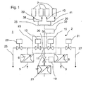
- the gas exchange device 2 comprises two supply lines 3, 5 for different precursor gases. For example, it is possible to supply a silicon precursor gas via one of the lines 3, 5 and a titanium precursor gas via the other of the lines 3, 5.
- the control of the gas flows of the precursor gases is carried out with mass flow controllers 6, 8.
- the leads 3, 5 openable by means of the valves 13, 15 in a gas mixing point 11. Also opens in this gas mixing point 11, which is arranged in the connection between the two valves , a supply line 17 for a further gas, which is mixed with the or each connected precursor gases in the gas mixing point 11.
- the supply line 17 is shut off by means of a valve 19 and the gas flow through this line 17 is controlled by a mass flow controller 21.
- the gas exchange device 2 also comprises two bypass lines 25, 27 which branch off from the supply lines 3, 5 in each case in front of the valves 13, 15 and which can each be shut off with a valve 29 or 31. These bypass lines are connected to one or more pumps.
- the deposition of multilayer coating systems requires the change between different precursor gases for the individual layer materials.
- the interface areas between the individual layers as fast as possible but at the same time possible mixing-free gas exchange is required.
- This stationary flow of a Precusorgases if just the corresponding layer material is deposited, passed into the gas mixing point 11, wherein in the supply line, the valve 13 or 15, depending on the required precursor gas open and the valve 29, or 31 in the bypass line closed is.
- the gas flow flows into the bypass line 25, or 27, wherein the respective valve 13, or 15 is closed.
- the decisive advantage of this principle is that no transient process of the gas flow, in particular no acceleration of an initially stationary gas column is required, until a stationary flow state is reached.
- the change from one precursor gas to another can therefore take place almost synchronously.
- the pressure in the bypass lines of the Precursorgase is identical to the pressure set in the gas mixing point so that regardless of whether the precursor gas is passed with the valves in the mixing point 11 or in the respective bypass line 25, or 27, prevail as identical pressure conditions ,
- the bypass lines 25, 27 effectively reflect the gas mixing point 11 in the event that the corresponding precursor gas is not needed in the process.
- the gas supply with precursor substances is thus realized by combining two valves 13, 29, or 15, 31 for each gas supply line 3, 5.
- the gas is then added either mixed with oxygen from the line 17 directly into the reaction chambers 7 or unused via the bypass line 25, or 27 discharged directly to the pump.
- a particularly preferred embodiment further comprises a gas mixing point with a dead space minimization, in particular in a mixing point valve.
- This mixing point valve is characterized in that it absolutely minimizes the dead space between the two gas supply lines 3, 5.
- the two valves 13, 15 of the two gas supply lines 3, 5 are brought as close as possible with their valve seats together.
- the sections 30, 50 of the supply lines 3, 5 between the valves 13, 15 and the gas mixing point 11 are kept as short as possible in order to achieve the fastest possible removal of the gas present in these sections in the event of a process gas change when the valves 13, 15 are shut off.
- the valve seats of the valves 13, 15 are integrated with the gas mixing point 11 in a mixing point valve unit in the form of a valve block 23, i. the two valve seats are themselves part of the valve block.
- the two gas supply lines 30, 50 in the vicinity of the gas mixing point 11 according to the invention should therefore preferably be designed so that the conduction path between the two valves 13, 15 is as short as possible.
- the gas needed for this coating can penetrate into the gas line of the other gas up to its valve. If the gas is changed, which is the case in optical switching layers in general every time switching from one coating material to the next, after the synchronous switching of the valves still some of the gas from the previous coating step with the new gas of the now desired coating is first mixed transported the CVD chamber and deposited there as a coating. Thus, at the first moment of each coating step, the gas composition is not well defined, and thus no precise, cleanly separated thin individual layers can be deposited in alternating layer systems for optical applications.
- the mass flow control of the gas supply system is realized by the installation of a needle valve or a very small aperture with a fixed fixed diameter in each of the supply lines, so in the pressure-controlled supply line 3, or 5 each precursor gas and in the pressure-controlled supply line 17 for oxygen.
- the bypass lines 25, 29 are also pressure-controlled.
- the execution of the needle valves or orifices and the adjustment of the pressures in the approaching lines is chosen such that at the location of the needle valves or diaphragms a greatly accelerated and substantially freed from reactions flow occurs. For the pressure conditions, this presupposes that the pressures in the respective distributor lines, ie the pre-pressures on the needle valves or diaphragms, are more than twice the back pressure.
- the back pressure corresponds to the pressure in the gas mixing point 11, in which the various process gases are brought together.
- the strong acceleration of the flow prevents the return transport of gas molecules by diffusion or flow from the gas mixing point 11 into the supply lines. A retroactive mixing of the different precursor gases is thus excluded.
- the strong acceleration of the flow in the case of flame formation at the gas mixing point or behind (in the direction the reaction chambers 7) a rear penetration of the flame front in the direction of the gas generating source. This creates a flashback lock.
- the pressure in the gas mixing point 11 depends on the amount of oxygen introduced, on the geometry of the gas mixing point and the line to the CVD reactor chamber and on the pressure in the CVD reactor chamber.
- the amount of Precursorgase is negligible compared to preferred modes in which more than 70% of oxygen in the process gas mixture are included, negligible.
- a typical value for the pressure at the gas mixing point is e.g. 10 mbar.
- the pressures in the feed lines 3, 5, 17 moving to the gas mixing point in front of the mass flow controllers 6, 8, 21 are set to at least 20 mbar, thus ensuring the strong acceleration of the gas. If the coating of certain substrates requires a significant increase in the oxygen flow, this results in an increase in the pressure in the gas mixing point 11. In this case, the pressures in the distribution lines may also be increased in order to guarantee the strong acceleration in the flow conditions.
- the gas supply to the gas supply to a CVD system with pressure-regulated supply lines and such discharges additionally equipped with needle valves in the gas supply lines and adjusted so that the needle valves the state of strong acceleration of the flow prevails in the flow direction of the gas supply, so the gas control can much more accurately and almost completely without feedback make than if the needle valves not would be included in the gas delivery system or not adjusted so that the physical state of that acceleration would prevail.
- This reaction would lead to a linear dependence (increase or decrease in the mass flow of the respective precursor gas), if the pressure would be far from the state of this strong acceleration of the flow in the flow direction (ie the pressure at the gas mixing point is not smaller by at least a factor of 2) would be the pressure in the pressure-controlled supply line).
- this acceleration also serves as a flame retardant and should in the case of flame formation at the gas mixing point or behind it (in the direction of the CVD reactors or reaction chambers) avoid a rear penetration of the flame front toward the gas generating source (large quantities of flammable and / or explosive reaction chemicals in large reservoirs) (flame back lock).
- the acceleration on the gas generator side must be at least twice as high as on the other side facing the valve block.
- a particularly preferred embodiment of the invention further comprises a bypass line 33 as part of the discharge from the gas mixing point 11 to the reaction chambers 7.
- the two gases combined in the gas mixing point are continued to the reaction chambers 7.
- the two combined gases must mix thoroughly. Since the two gases in the gas mixing point from the two supply lines from two sides flow into the common derivative, they will not mix by themselves at the prevailing pressures and only insufficiently (no turbulent flow).
- a preferred measure according to the invention is, as shown in Fig. 1, the laying of the line to the reactor in the form of detour lines with loops, S-curves, meandering, etc., wherein in each case a turbulent mixing of the at least two types of gas takes place in the sheets.
- the manifold used in the preferred embodiments is of great importance, because the manifold has the Aukebe to direct the incoming gas mixture as evenly as possible to the individual coating stations.
- the structural feature that the distributor tube is constructed as a double tube is advantageous for the uniform distribution of the gas flow over the plurality of branches to the individual coating stations.
- the central supply pipe runs with the distribution of the gas flow on the individual discharges to the coating stations, while in another plane, e.g. Below this level, one or more discharge line (s) are arranged to the pump.
- each of 5 supply lines are included: each one inlet and one outlet, or bypass for each of the two types of gas and a supply of oxygen. It is advantageous if each of these distribution lines is designed according to the construction principle according to the invention, in order to achieve as uniform a gas flow as possible.
- a station distribution in modular construction is particularly preferably carried out.
- each reaction chamber 7 a single gas mixing point 11 with circuit of the associated valves 13, 15, 29, 31 to build a valve block 23, as stated above, but it is particularly advantageous from a gas mixing point 11 instead behind the subsequent mixing line, or detour line 33 for the purpose of generating turbulence splitting a branch line into a plurality of individual separate individual lines, each leading into a coating station.
- the branch line coming from the gas mixing point 11 is first divided symmetrically into two lines 35, 36. These two lines can then in each case be split symmetrically, as shown in FIG. 1, again into two further lines 38, 39, or 40, 41, etc., so that from a gas mixing point of 2, 4, 8, 16 .. ., Individual CVD coating reactors, or reaction chambers 7 can be supplied with a uniform mass flow of gas.
- FIG. 2 A schematic representation of such a development of the invention is shown in FIG. 2 in a schematic perspective view.
- the coating installation 1 comprises a plurality of modules 45, 46, 47, each with a plurality of reaction chambers 7.
- the reaction chambers 7 are each connected in the modules 45, 46, 47 to a gas supply system 48 which, as described above, distributes the gas mixture 11 of the gas mixture Module has outgoing derivative in 2n branches, wherein from each branch point exactly two branches go out and the branches opening into the reaction chambers 7 branches are divided equally often.
- the lines of the gas supply systems 48 are in each module in each case in parallel planes 50, wherein the gas mixing points 11 are lined up along a direction 51 perpendicular to these planes 50 direction.
- the switching of the pairs of valves 13, 29 and 15, 31 of the embodiment shown in Fig. 1 for the change of the process gas mixture must not be synchronous, but may be delayed.
- the changeover of the valves 13, 29 as well as the switching of the valves 15, 31 is carried out synchronously, but can be maintained by means of a suitable control a pause between the opening of the valve 15 and the closing of the valve 13 and vice versa. This pause causes the gas flow in the form of discrete gas pulses to the Reaction chambers is passed so that the different process gas mixtures of successive gas pulses do not mix with each other.
- FIG. 3 shows a diagram of the time profile of the mass flow in the discharge to the reaction chambers for clarification.
- gas pulses 60 of a first precursor gas mixture and gas pulses 61 of a second precursor gas mixture are conducted from the gas mixing point through the discharge line.
- the mass flows of the gas pulses 60, 61 can also be different. This is especially true for their length.
- the layer thickness is higher in the low-index layers.
- the gas pulses for the low-index layers are set correspondingly longer.
- the longer gas pulses 60 gas pulses of a gas mixture with a silicon precursor for the deposition of SiO 2 layers and the shorter gas pulses 61 gas pulses of a gas mixture with a titanium precursor for the deposition of higher refractive TiO 2 layers be.
- the pauses 62, 63 are as short as possible. Ideally, an operation is sought in which the gas pulses follow each other directly, without mixing the Gas types occurs. Accordingly, the pauses 62, 63 should be as short as possible and may ideally disappear.
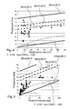
- FIGS. 4 and 5 Practical values of plasma pulse pauses in the deposition of TiO 2 / SiO 2 interference alternating layers as a function of the reactor volume are shown in the diagrams of FIGS. 4 and 5.
- FIG. 4 glass-ceramic reflectors were coated.
- FIG. 5 shows corresponding values for the coating of reflectors made of suprax glass. The values shown proved to be particularly favorable in order to obtain qualitatively very high-quality alternating layers with sharp boundary surfaces.
- pulse pause between temporally adjacent plasma pulses can thus be limited in time to this upper limit, without adverse effects on the formation of the interfaces and the layer purity arise.
- FIGS. 4 and 5 two straight lines are shown, which correspond to the two preceding relationships. It can be seen from FIGS. 4 and 5 that these limit values are well suited both for glass substrates (FIG. 5) and for glass-ceramic substrates (FIG. 4), in particular for larger reactor volumes, preferably greater than 100 milliliters.
- the function P [ms] V * [(1/6) * exp (-V / 300) + (1/20)] is shown in FIGS. 4 and 5 for illustrative purposes. In particular, it can be seen from the values shown in Figure 5 that this function closely approximates the lower limit for optimum coating over a wide volume range.
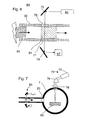
- FIG. 6 shows an exemplary embodiment of an optical arrangement 64 with which the temporal density profile or the temporal course of the mass flows of the gas pulses can be detected.
- windows 70, 71 are provided, so that the light beam of a light source 65 is passed through the line 33 and the outgoing light beam can be detected with a spectrometer 67.
- the light beam is also deflected by two mirrors 73, 74.
- the mirrors can themselves be part of the spectrometer.
- the mirror 74 may be dichroic and reflect only excited fluorescent light and transmit the light from the light source.
- the mirror 74 may be a grating to achieve spectral splitting.
- fluorescence or absorption lines of the gas mixture of the transmitted pulses 60, 61 can be detected, and the duration of the pulses 60, 61 can be monitored on the basis of their intensity.
- the optical assembly 64 for controlling the gas supply, in particular the gas exchange device serve. Namely, with the arrangement, a measure of the actual amount of gas passed can be obtained.
- a controller could be such that the valves of the respective precursor gas are switched over when the gas quantity determined on the basis of the measured values is passed through. The switching of the valves for the additional precursor gas then takes place after the predetermined pulse pause.
- detection of one or more emission lines of the plasma may similarly occur.
- the optical assembly is placed in or out of the reaction chamber. Since the plasma itself is lit, the light source 65 can be omitted in this case. Also, a record of the intensity of a particular emission line can be used to control the pulse length of the gas pulses.
- a CVD reactor having such an exemplary optical arrangement 75 is shown schematically in FIG.
- an optical arrangement according to FIG. 6 is also connected.
- an object 80 to be coated is arranged and the reaction chamber is evacuated.
- a detour line 33 gas pulses are introduced and ignited by means not shown for irradiating electromagnetic energy in the filled with the process gas mixture reactor volume a plasma.
- a microwave source can be used as a means for irradiating electromagnetic energy.
- a window 78 in the wall of the reaction chamber 7 light, which is formed in the plasma, passes to the outside.
- the light is decomposed into its spectral components and recorded with a camera 77 or other detection device.
- the Intensity of a certain emission line of the precursor gas can thus be detected time-resolved in order to obtain an accurate measure of the amount of deposited material.
- This arrangement like the optical arrangement 64, can accordingly be used to control the pulse length of the gas pulses via the gas exchange device.
- the term "article” includes both planar and non-planar three-dimensionally shaped substrates or products, such as optical components, reflectors, lenses, ophthalmic glasses, or plastics, such as for use in eyeglasses, display glasses, automotive parts such as instrument, illuminant covers or discs, lamps or bulbs, such as flasher bulbs, halogen, in particular H3 and H4 bulbs or high-pressure bulbs.
- the coating described above may serve for the spectral influence and / or the change of the reflection and / or the absorption capacity.
- barrier or defined migration layers Due to the particularly precise control of the density, the composition and the thickness of the layer, it is also possible to produce barrier or defined migration layers with the invention.
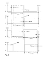
- Figs. 8A to 8C show a schematic of the pulse series used to deposit a alternating layer system.
- different parameters can be used in addition to a different process gas composition, such as, in particular, the pulse height, pulse duration, pulse pause and possibly also the pulse shape of the electromagnetic pulses are used.
- the pulse series with these parameters are also referred to as "tracks" in the following.
- tracks In the timing diagram of FIG. 8A, such a track 85 designated as track 1 is shown.
- the source in this case a microwave source, is pulsed, so that during this time a pulse train of plasma pulses is generated.
- the source in this case a microwave source
- Fig. 8B the light signal of the plasma is shown as a function of time.
- Fig. 8C shows a time-stretched portion of the diagram of Fig. 8B.
- the plasma pulses 90 have a length of duration 91 and are spaced in time by pauses 92, wherein in the example shown the pauses 92 are selected to be longer than the pulse durations 91.
- the plasma pulses of the pulse series manifest themselves as flashes of light, wherein, as shown by the example of FIG. 8B, the light flashes of different tracks can also have different intensities. Also, the pauses in the pulses are different in the example of the tracks 85, 86 shown in Fig. 8B.
- microwave pulses between the two tracks 85, 86 are interrupted.
- the duration "MW off” of this interruption ie the duration between the times “MW track 2 off” and “MW track 1 on”, or “MW track 1 off” and “MW track 2 on”, is generally longer than that Pulse break between the individual plasma pulses within the tracks, or pulse series.
- the pulse duration 91 (ie the MW energy is "on") generally has values between 0.6 and 1.2 ms, in exceptional cases also less or more.
- the pulse interval 92 between the individual pulses (ie the MW energy is "off", but the gas flows continuously) is according to the invention at least so long that a complete gas exchange in the reactor volume can take place, otherwise the reflector will only be at the next MW pulse partly coated. This pulse pause is plotted in FIGS. 4 and 5 as ordinate.
- the pause of the pulse can also be selected significantly longer than the minimum time required for a complete gas exchange. Longer intervals between pulses 92 have proven to be favorable, in particular, in coating processes on glass-ceramic substrates.
- a gas exchange is to be understood as a change between two precursor gases, such as a change between HMDSO + O 2 and TiCl 4 + O 2 .
- FIG. 9 shows four timing diagrams.
- the top time diagram (“valve 1") shows the time-dependent switching state of one of the valves 13, 15 of the arrangement shown in Fig. 1, the diagram "valve 2" the switching state of the other of the two valves.
- the other two diagrams show the switching states of the two tracks, or Pulseerien 85, 86.
- the valve 1, the track 85 and the valve 2, the track 86 is assigned. This means that with the process gas introduced through valve 1, a layer is deposited by means of the process parameters of lane 85 and with the process gas introduced through valve 2 by means of the process parameters of lane 86.
- the time required for the gas from the valve 1 to the reaction volume, such as the volume of the concave inner portion of a reflector, is the lead time t lead .
- the valve is opened, after the lead time the corresponding microwave track is switched on.
- the lead time or follow-up time is essentially dependent on the geometry of the coating system.
- the lead time is ideally equal to the lag time.
- the source such as for example a microwave
- the source could theoretically be activated throughout the entire time, ie, couple power into the reactor volume continuously during pulsed operation. It would only be switched at certain times, the power of the source of the settings for the one track to that for the other track.
- this period of time should be kept as short as possible in order to maximize the coating performance of the system.
Landscapes
- Chemical & Material Sciences (AREA)
- Engineering & Computer Science (AREA)
- Materials Engineering (AREA)
- General Chemical & Material Sciences (AREA)
- Chemical Kinetics & Catalysis (AREA)
- Mechanical Engineering (AREA)
- Metallurgy (AREA)
- Organic Chemistry (AREA)
- Plasma & Fusion (AREA)
- Physics & Mathematics (AREA)
- Chemical Vapour Deposition (AREA)
- Application Of Or Painting With Fluid Materials (AREA)
- Nozzles (AREA)
- Physical Vapour Deposition (AREA)
Applications Claiming Priority (2)
| Application Number | Priority Date | Filing Date | Title |
|---|---|---|---|
| DE102006053365 | 2006-11-10 | ||
| DE102007037527A DE102007037527B4 (de) | 2006-11-10 | 2007-08-09 | Verfahren zum Beschichten von Gegenständen mit Wechselschichten |
Publications (3)
| Publication Number | Publication Date |
|---|---|
| EP1921179A2 true EP1921179A2 (fr) | 2008-05-14 |
| EP1921179A3 EP1921179A3 (fr) | 2008-06-25 |
| EP1921179B1 EP1921179B1 (fr) | 2012-01-11 |
Family
ID=39048833
Family Applications (1)
| Application Number | Title | Priority Date | Filing Date |
|---|---|---|---|
| EP07021685A Active EP1921179B1 (fr) | 2006-11-10 | 2007-11-08 | Installation de revêtement et procédé de revêtement |
Country Status (8)
| Country | Link |
|---|---|
| US (1) | US8268410B2 (fr) |
| EP (1) | EP1921179B1 (fr) |
| JP (1) | JP5026229B2 (fr) |
| KR (1) | KR101411632B1 (fr) |
| CN (1) | CN101225514B (fr) |
| AT (1) | ATE541066T1 (fr) |
| DE (1) | DE102007037527B4 (fr) |
| TW (1) | TWI401335B (fr) |
Cited By (1)
| Publication number | Priority date | Publication date | Assignee | Title |
|---|---|---|---|---|
| WO2012051975A1 (fr) * | 2010-10-18 | 2012-04-26 | Khs Corpoplast Gmbh & Co Kg | Procédé et dispositif de traitement au plasma de pièces |
Families Citing this family (29)
| Publication number | Priority date | Publication date | Assignee | Title |
|---|---|---|---|---|
| WO2006098450A1 (fr) * | 2005-03-18 | 2006-09-21 | Mitsubishi Chemical Corporation | Dispositif luminescent, dispositif luminescent blanc, dispositif d’éclairage et affichage d’image |
| EP2251455B1 (fr) | 2009-05-13 | 2017-09-06 | SiO2 Medical Products, Inc. | Revêtement PECVD utilisant un précurseur organosilicié |
| US9458536B2 (en) | 2009-07-02 | 2016-10-04 | Sio2 Medical Products, Inc. | PECVD coating methods for capped syringes, cartridges and other articles |
| US11624115B2 (en) | 2010-05-12 | 2023-04-11 | Sio2 Medical Products, Inc. | Syringe with PECVD lubrication |
| US9878101B2 (en) | 2010-11-12 | 2018-01-30 | Sio2 Medical Products, Inc. | Cyclic olefin polymer vessels and vessel coating methods |
| US9272095B2 (en) | 2011-04-01 | 2016-03-01 | Sio2 Medical Products, Inc. | Vessels, contact surfaces, and coating and inspection apparatus and methods |
| US11116695B2 (en) | 2011-11-11 | 2021-09-14 | Sio2 Medical Products, Inc. | Blood sample collection tube |
| CN103930595A (zh) | 2011-11-11 | 2014-07-16 | Sio2医药产品公司 | 用于药物包装的钝化、pH保护性或润滑性涂层、涂布方法以及设备 |
| CA2887352A1 (fr) | 2012-05-09 | 2013-11-14 | Sio2 Medical Products, Inc. | Enrobage protecteur en saccharide pour conditionnement pharmaceutique |
| US20150297800A1 (en) | 2012-07-03 | 2015-10-22 | Sio2 Medical Products, Inc. | SiOx BARRIER FOR PHARMACEUTICAL PACKAGE AND COATING PROCESS |
| JP6509734B2 (ja) | 2012-11-01 | 2019-05-08 | エスアイオーツー・メディカル・プロダクツ・インコーポレイテッド | 皮膜検査方法 |
| US9903782B2 (en) | 2012-11-16 | 2018-02-27 | Sio2 Medical Products, Inc. | Method and apparatus for detecting rapid barrier coating integrity characteristics |
| US9764093B2 (en) | 2012-11-30 | 2017-09-19 | Sio2 Medical Products, Inc. | Controlling the uniformity of PECVD deposition |
| WO2014085348A2 (fr) | 2012-11-30 | 2014-06-05 | Sio2 Medical Products, Inc. | Contrôle de l'uniformité de dépôt chimique en phase vapeur activé par plasma (pecvd) sur des seringues médicales, des cartouches et analogues |
| EP2961858B1 (fr) | 2013-03-01 | 2022-09-07 | Si02 Medical Products, Inc. | Seringue revetu. |
| US9937099B2 (en) | 2013-03-11 | 2018-04-10 | Sio2 Medical Products, Inc. | Trilayer coated pharmaceutical packaging with low oxygen transmission rate |
| CN105392916B (zh) | 2013-03-11 | 2019-03-08 | Sio2医药产品公司 | 涂布包装材料 |
| EP2971227B1 (fr) | 2013-03-15 | 2017-11-15 | Si02 Medical Products, Inc. | Procede de revetement. |
| CN103762321B (zh) * | 2013-12-31 | 2017-06-09 | 中山市贝利斯特包装制品有限公司 | 一种有机器件薄膜封装方法及装置 |
| CN103757607A (zh) * | 2013-12-31 | 2014-04-30 | 刘键 | 一种有机器件封装方法及装置 |
| US11066745B2 (en) | 2014-03-28 | 2021-07-20 | Sio2 Medical Products, Inc. | Antistatic coatings for plastic vessels |
| CN105590825A (zh) * | 2014-11-03 | 2016-05-18 | 中微半导体设备(上海)有限公司 | 气体输送装置及等离子体处理装置 |
| US11077233B2 (en) | 2015-08-18 | 2021-08-03 | Sio2 Medical Products, Inc. | Pharmaceutical and other packaging with low oxygen transmission rate |
| KR101975868B1 (ko) * | 2018-03-21 | 2019-05-07 | 유림에코 주식회사 | 부표 코팅 조성물을 이용한 부표 |
| KR101975872B1 (ko) * | 2018-03-21 | 2019-09-10 | 유림에코 주식회사 | 부표 코팅 조성물을 이용한 부표 |
| KR102086574B1 (ko) * | 2018-04-03 | 2020-03-09 | 전남대학교산학협력단 | 분말 입자를 코팅할 수 있는 증착장치 및 분말 입자의 코팅 방법 |
| DE102018132700A1 (de) * | 2018-12-18 | 2020-06-18 | Krones Ag | Vorrichtung und Verfahren zum Beschichten und insbesondere Plasmabeschichten von Behältnissen |
| DE102023123027A1 (de) * | 2023-08-28 | 2025-03-06 | Khs Gmbh | Beschichtungsstation für die gleichzeitige Beschichtung von mehreren Behältern in einem auf der Beschichtungsstation ablaufenden Beschichtungsverfahren |
| CN117612920B (zh) * | 2024-01-23 | 2024-04-05 | 上海邦芯半导体科技有限公司 | 反应气体切换系统及等离子体处理装置 |
Citations (1)
| Publication number | Priority date | Publication date | Assignee | Title |
|---|---|---|---|---|
| EP0519215B1 (fr) | 1991-06-19 | 1995-08-30 | Schott Glaswerke | Dispositif et installation pour le revêtement de substrats sous la forme de calotte |
Family Cites Families (13)
| Publication number | Priority date | Publication date | Assignee | Title |
|---|---|---|---|---|
| US4761269A (en) * | 1986-06-12 | 1988-08-02 | Crystal Specialties, Inc. | Apparatus for depositing material on a substrate |
| US5146869A (en) * | 1990-06-11 | 1992-09-15 | National Semiconductor Corporation | Tube and injector for preheating gases in a chemical vapor deposition reactor |
| JP3172537B2 (ja) | 1994-03-29 | 2001-06-04 | カール−ツァイス−スティフツング | 湾曲した基材のコーティング用pcvd法及び装置 |
| JP3775689B2 (ja) * | 1997-04-21 | 2006-05-17 | トーキョー エレクトロン アリゾナ インコーポレイテッド | 材料をイオン化スパッタリングする方法と装置 |
| US6511539B1 (en) * | 1999-09-08 | 2003-01-28 | Asm America, Inc. | Apparatus and method for growth of a thin film |
| JP4703810B2 (ja) * | 2000-03-07 | 2011-06-15 | 東京エレクトロン株式会社 | Cvd成膜方法 |
| KR100443908B1 (ko) * | 2001-10-25 | 2004-08-09 | 삼성전자주식회사 | 플라즈마 화학기상증착장치 및 이를 이용한나이트라이드막 형성방법 |
| JP4908738B2 (ja) * | 2002-01-17 | 2012-04-04 | サンデュー・テクノロジーズ・エルエルシー | Ald方法 |
| DE10258678B4 (de) | 2002-12-13 | 2004-12-30 | Schott Ag | Schnelles Verfahren zur Herstellung von Multilayer-Barriereschichten |
| AR047196A1 (es) * | 2002-12-04 | 2006-01-11 | Dana Corp | Sistema y metodo de tratamiento de gases de escape de motores y vehiculo movil que contiene al sistema |
| US20050260354A1 (en) * | 2004-05-20 | 2005-11-24 | Varian Semiconductor Equipment Associates, Inc. | In-situ process chamber preparation methods for plasma ion implantation systems |
| DE102004042431B4 (de) * | 2004-08-31 | 2008-07-03 | Schott Ag | Verfahren und Vorrichtung zur Plasmabeschichtung von Werkstücken mit spektraler Auswertung der Prozessparameter und Verwendung der Vorrichtung |
| US7959984B2 (en) * | 2004-12-22 | 2011-06-14 | Lam Research Corporation | Methods and arrangement for the reduction of byproduct deposition in a plasma processing system |
-
2007
- 2007-08-09 DE DE102007037527A patent/DE102007037527B4/de not_active Expired - Fee Related
- 2007-11-07 TW TW096142010A patent/TWI401335B/zh not_active IP Right Cessation
- 2007-11-08 JP JP2007290709A patent/JP5026229B2/ja active Active
- 2007-11-08 US US11/937,279 patent/US8268410B2/en active Active
- 2007-11-08 EP EP07021685A patent/EP1921179B1/fr active Active
- 2007-11-08 AT AT07021685T patent/ATE541066T1/de active
- 2007-11-09 KR KR1020070114462A patent/KR101411632B1/ko not_active Expired - Fee Related
- 2007-11-09 CN CN2007101997826A patent/CN101225514B/zh active Active
Patent Citations (1)
| Publication number | Priority date | Publication date | Assignee | Title |
|---|---|---|---|---|
| EP0519215B1 (fr) | 1991-06-19 | 1995-08-30 | Schott Glaswerke | Dispositif et installation pour le revêtement de substrats sous la forme de calotte |
Cited By (2)
| Publication number | Priority date | Publication date | Assignee | Title |
|---|---|---|---|---|
| WO2012051975A1 (fr) * | 2010-10-18 | 2012-04-26 | Khs Corpoplast Gmbh & Co Kg | Procédé et dispositif de traitement au plasma de pièces |
| US9169559B2 (en) | 2010-10-18 | 2015-10-27 | Khs Corpoplast Gmbh | Method for plasma-treating workpieces |
Also Published As
| Publication number | Publication date |
|---|---|
| KR20080042753A (ko) | 2008-05-15 |
| TWI401335B (zh) | 2013-07-11 |
| US8268410B2 (en) | 2012-09-18 |
| TW200902749A (en) | 2009-01-16 |
| US20080113109A1 (en) | 2008-05-15 |
| CN101225514B (zh) | 2010-12-01 |
| DE102007037527B4 (de) | 2013-05-08 |
| JP2008169471A (ja) | 2008-07-24 |
| EP1921179A3 (fr) | 2008-06-25 |
| CN101225514A (zh) | 2008-07-23 |
| EP1921179B1 (fr) | 2012-01-11 |
| ATE541066T1 (de) | 2012-01-15 |
| DE102007037527A1 (de) | 2008-05-15 |
| JP5026229B2 (ja) | 2012-09-12 |
| KR101411632B1 (ko) | 2014-06-25 |
Similar Documents
| Publication | Publication Date | Title |
|---|---|---|
| EP1921179B1 (fr) | Installation de revêtement et procédé de revêtement | |
| DE3926023C2 (fr) | ||
| EP1921656B1 (fr) | Procédé et dispositif de dépôt chimique en phase vapeur assisté de plasma | |
| DE68917563T2 (de) | Verfahren zur Herstellung von Pigmentschuppen. | |
| DE3830249C2 (fr) | ||
| DE3610298C2 (fr) | ||
| DE19629877C1 (de) | CVD-Verfahren und Vorrichtung zur Innenbeschichtung von Hohlkörpern | |
| DE3610295C2 (de) | Verfahren und Vorrichtung zur Umsetzung von Rohmaterialien | |
| EP2521804B1 (fr) | Installation de revêtement en ligne | |
| EP1415321A1 (fr) | Dispositif pour munir des objets d'un revetement | |
| EP0501016A1 (fr) | Méthode de réglage d'un procédé de pulvérisation cathodique réactive et dispositif pour réaliser la méthode | |
| DE19912737A1 (de) | Verfahren zur Herstellung von porösen SiO¶x¶-Schichten und poröse SiO¶x¶-Schichten | |
| EP1394283A1 (fr) | Procédé et dispositif pour le revêtement de substrats de grande surface à pression atmospherique | |
| DE10347521A1 (de) | Verfahren zur Herstellung Multilayerschicht und Vorrichtung zur Durchführung des Verfahrens | |
| EP0595159B1 (fr) | Procédé et appareillage pour revêtir par CVD l'intérieur des substrats fortement courbés sous la forme de calotte | |
| CH689595A5 (de) | Verfahren und Vorrichtung zum Beschichten von optischen Linsen mit Schutzschichten und mit optischen Schichten im Vakuum. | |
| EP3810826A1 (fr) | Dispositif destiné à recouvrir des récipients d'une couche de barrière et procédé de chauffage d'un récipient | |
| DE10143145C1 (de) | Verfahren und Einrichtung zur Herstellung von Schichtsystemen für optische Präzisionselemente | |
| DE69402742T2 (de) | Vorrichtung zur Verteilung von pulverförmigen Feststoffen auf ein Substrat zum Zweck seiner Beschichtung | |
| DE3610296C2 (fr) | ||
| DE3610294C2 (fr) | ||
| EP4488407A1 (fr) | Dispositif d'alimentation d'une installation de revêtement en gaz de processus requis et procédé de fonctionnement d'un tel dispositif d'alimentation en gaz | |
| EP4417730A1 (fr) | Dispositif et procédé d'alimentation d'une installation de revêtement de pièces avec des gaz de processus nécessaires au processus de revêtement | |
| EP4147264B1 (fr) | Dispositif et procédé pour revêtement de récipients | |
| DE10102611A1 (de) | Verfahren zur Herstellung eines SiO¶2¶-Rohlings |
Legal Events
| Date | Code | Title | Description |
|---|---|---|---|
| PUAI | Public reference made under article 153(3) epc to a published international application that has entered the european phase |
Free format text: ORIGINAL CODE: 0009012 |
|
| 17P | Request for examination filed |
Effective date: 20071130 |
|
| AK | Designated contracting states |
Kind code of ref document: A2 Designated state(s): AT BE BG CH CY CZ DE DK EE ES FI FR GB GR HU IE IS IT LI LT LU LV MC MT NL PL PT RO SE SI SK TR |
|
| AX | Request for extension of the european patent |
Extension state: AL BA HR MK RS |
|
| PUAL | Search report despatched |
Free format text: ORIGINAL CODE: 0009013 |
|
| AK | Designated contracting states |
Kind code of ref document: A3 Designated state(s): AT BE BG CH CY CZ DE DK EE ES FI FR GB GR HU IE IS IT LI LT LU LV MC MT NL PL PT RO SE SI SK TR |
|
| AX | Request for extension of the european patent |
Extension state: AL BA HR MK RS |
|
| 17Q | First examination report despatched |
Effective date: 20080917 |
|
| AKX | Designation fees paid |
Designated state(s): AT BE BG CH CY CZ DE DK EE ES FI FR GB GR HU IE IS IT LI LT LU LV MC MT NL PL PT RO SE SI SK TR |
|
| GRAP | Despatch of communication of intention to grant a patent |
Free format text: ORIGINAL CODE: EPIDOSNIGR1 |
|
| GRAS | Grant fee paid |
Free format text: ORIGINAL CODE: EPIDOSNIGR3 |
|
| GRAA | (expected) grant |
Free format text: ORIGINAL CODE: 0009210 |
|
| AK | Designated contracting states |
Kind code of ref document: B1 Designated state(s): AT BE BG CH CY CZ DE DK EE ES FI FR GB GR HU IE IS IT LI LT LU LV MC MT NL PL PT RO SE SI SK TR |
|
| REG | Reference to a national code |
Ref country code: GB Ref legal event code: FG4D Free format text: NOT ENGLISH |
|
| REG | Reference to a national code |
Ref country code: CH Ref legal event code: NV Representative=s name: BOVARD AG Ref country code: CH Ref legal event code: EP |
|
| REG | Reference to a national code |
Ref country code: AT Ref legal event code: REF Ref document number: 541066 Country of ref document: AT Kind code of ref document: T Effective date: 20120115 |
|
| REG | Reference to a national code |
Ref country code: IE Ref legal event code: FG4D |
|
| REG | Reference to a national code |
Ref country code: DE Ref legal event code: R096 Ref document number: 502007009036 Country of ref document: DE Effective date: 20120315 |
|
| REG | Reference to a national code |
Ref country code: NL Ref legal event code: T3 |
|
| PG25 | Lapsed in a contracting state [announced via postgrant information from national office to epo] |
Ref country code: SI Free format text: LAPSE BECAUSE OF FAILURE TO SUBMIT A TRANSLATION OF THE DESCRIPTION OR TO PAY THE FEE WITHIN THE PRESCRIBED TIME-LIMIT Effective date: 20120111 |
|
| LTIE | Lt: invalidation of european patent or patent extension |
Effective date: 20120111 |
|
| PG25 | Lapsed in a contracting state [announced via postgrant information from national office to epo] |
Ref country code: BG Free format text: LAPSE BECAUSE OF FAILURE TO SUBMIT A TRANSLATION OF THE DESCRIPTION OR TO PAY THE FEE WITHIN THE PRESCRIBED TIME-LIMIT Effective date: 20120411 Ref country code: IS Free format text: LAPSE BECAUSE OF FAILURE TO SUBMIT A TRANSLATION OF THE DESCRIPTION OR TO PAY THE FEE WITHIN THE PRESCRIBED TIME-LIMIT Effective date: 20120511 Ref country code: LT Free format text: LAPSE BECAUSE OF FAILURE TO SUBMIT A TRANSLATION OF THE DESCRIPTION OR TO PAY THE FEE WITHIN THE PRESCRIBED TIME-LIMIT Effective date: 20120111 |
|
| REG | Reference to a national code |
Ref country code: IE Ref legal event code: FD4D |
|
| PG25 | Lapsed in a contracting state [announced via postgrant information from national office to epo] |
Ref country code: PL Free format text: LAPSE BECAUSE OF FAILURE TO SUBMIT A TRANSLATION OF THE DESCRIPTION OR TO PAY THE FEE WITHIN THE PRESCRIBED TIME-LIMIT Effective date: 20120111 Ref country code: FI Free format text: LAPSE BECAUSE OF FAILURE TO SUBMIT A TRANSLATION OF THE DESCRIPTION OR TO PAY THE FEE WITHIN THE PRESCRIBED TIME-LIMIT Effective date: 20120111 Ref country code: PT Free format text: LAPSE BECAUSE OF FAILURE TO SUBMIT A TRANSLATION OF THE DESCRIPTION OR TO PAY THE FEE WITHIN THE PRESCRIBED TIME-LIMIT Effective date: 20120511 Ref country code: LV Free format text: LAPSE BECAUSE OF FAILURE TO SUBMIT A TRANSLATION OF THE DESCRIPTION OR TO PAY THE FEE WITHIN THE PRESCRIBED TIME-LIMIT Effective date: 20120111 Ref country code: GR Free format text: LAPSE BECAUSE OF FAILURE TO SUBMIT A TRANSLATION OF THE DESCRIPTION OR TO PAY THE FEE WITHIN THE PRESCRIBED TIME-LIMIT Effective date: 20120412 |
|
| PG25 | Lapsed in a contracting state [announced via postgrant information from national office to epo] |
Ref country code: CY Free format text: LAPSE BECAUSE OF FAILURE TO SUBMIT A TRANSLATION OF THE DESCRIPTION OR TO PAY THE FEE WITHIN THE PRESCRIBED TIME-LIMIT Effective date: 20120111 |
|
| PG25 | Lapsed in a contracting state [announced via postgrant information from national office to epo] |
Ref country code: CZ Free format text: LAPSE BECAUSE OF FAILURE TO SUBMIT A TRANSLATION OF THE DESCRIPTION OR TO PAY THE FEE WITHIN THE PRESCRIBED TIME-LIMIT Effective date: 20120111 Ref country code: RO Free format text: LAPSE BECAUSE OF FAILURE TO SUBMIT A TRANSLATION OF THE DESCRIPTION OR TO PAY THE FEE WITHIN THE PRESCRIBED TIME-LIMIT Effective date: 20120111 Ref country code: SE Free format text: LAPSE BECAUSE OF FAILURE TO SUBMIT A TRANSLATION OF THE DESCRIPTION OR TO PAY THE FEE WITHIN THE PRESCRIBED TIME-LIMIT Effective date: 20120111 Ref country code: IE Free format text: LAPSE BECAUSE OF FAILURE TO SUBMIT A TRANSLATION OF THE DESCRIPTION OR TO PAY THE FEE WITHIN THE PRESCRIBED TIME-LIMIT Effective date: 20120111 Ref country code: EE Free format text: LAPSE BECAUSE OF FAILURE TO SUBMIT A TRANSLATION OF THE DESCRIPTION OR TO PAY THE FEE WITHIN THE PRESCRIBED TIME-LIMIT Effective date: 20120111 Ref country code: DK Free format text: LAPSE BECAUSE OF FAILURE TO SUBMIT A TRANSLATION OF THE DESCRIPTION OR TO PAY THE FEE WITHIN THE PRESCRIBED TIME-LIMIT Effective date: 20120111 |
|
| PLBE | No opposition filed within time limit |
Free format text: ORIGINAL CODE: 0009261 |
|
| STAA | Information on the status of an ep patent application or granted ep patent |
Free format text: STATUS: NO OPPOSITION FILED WITHIN TIME LIMIT |
|
| PG25 | Lapsed in a contracting state [announced via postgrant information from national office to epo] |
Ref country code: IT Free format text: LAPSE BECAUSE OF FAILURE TO SUBMIT A TRANSLATION OF THE DESCRIPTION OR TO PAY THE FEE WITHIN THE PRESCRIBED TIME-LIMIT Effective date: 20120111 Ref country code: SK Free format text: LAPSE BECAUSE OF FAILURE TO SUBMIT A TRANSLATION OF THE DESCRIPTION OR TO PAY THE FEE WITHIN THE PRESCRIBED TIME-LIMIT Effective date: 20120111 |
|
| 26N | No opposition filed |
Effective date: 20121012 |
|
| REG | Reference to a national code |
Ref country code: DE Ref legal event code: R097 Ref document number: 502007009036 Country of ref document: DE Effective date: 20121012 |
|
| PG25 | Lapsed in a contracting state [announced via postgrant information from national office to epo] |
Ref country code: ES Free format text: LAPSE BECAUSE OF FAILURE TO SUBMIT A TRANSLATION OF THE DESCRIPTION OR TO PAY THE FEE WITHIN THE PRESCRIBED TIME-LIMIT Effective date: 20120422 |
|
| PG25 | Lapsed in a contracting state [announced via postgrant information from national office to epo] |
Ref country code: MT Free format text: LAPSE BECAUSE OF FAILURE TO SUBMIT A TRANSLATION OF THE DESCRIPTION OR TO PAY THE FEE WITHIN THE PRESCRIBED TIME-LIMIT Effective date: 20120111 |
|
| REG | Reference to a national code |
Ref country code: AT Ref legal event code: MM01 Ref document number: 541066 Country of ref document: AT Kind code of ref document: T Effective date: 20121130 |
|
| PG25 | Lapsed in a contracting state [announced via postgrant information from national office to epo] |
Ref country code: AT Free format text: LAPSE BECAUSE OF NON-PAYMENT OF DUE FEES Effective date: 20121130 |
|
| PG25 | Lapsed in a contracting state [announced via postgrant information from national office to epo] |
Ref country code: MC Free format text: LAPSE BECAUSE OF NON-PAYMENT OF DUE FEES Effective date: 20121130 Ref country code: TR Free format text: LAPSE BECAUSE OF FAILURE TO SUBMIT A TRANSLATION OF THE DESCRIPTION OR TO PAY THE FEE WITHIN THE PRESCRIBED TIME-LIMIT Effective date: 20120111 |
|
| PG25 | Lapsed in a contracting state [announced via postgrant information from national office to epo] |
Ref country code: LU Free format text: LAPSE BECAUSE OF NON-PAYMENT OF DUE FEES Effective date: 20121108 |
|
| PG25 | Lapsed in a contracting state [announced via postgrant information from national office to epo] |
Ref country code: HU Free format text: LAPSE BECAUSE OF FAILURE TO SUBMIT A TRANSLATION OF THE DESCRIPTION OR TO PAY THE FEE WITHIN THE PRESCRIBED TIME-LIMIT Effective date: 20071108 |
|
| REG | Reference to a national code |
Ref country code: FR Ref legal event code: PLFP Year of fee payment: 9 |
|
| REG | Reference to a national code |
Ref country code: FR Ref legal event code: PLFP Year of fee payment: 10 |
|
| REG | Reference to a national code |
Ref country code: FR Ref legal event code: PLFP Year of fee payment: 11 |
|
| PGFP | Annual fee paid to national office [announced via postgrant information from national office to epo] |
Ref country code: NL Payment date: 20191120 Year of fee payment: 13 |
|
| PGFP | Annual fee paid to national office [announced via postgrant information from national office to epo] |
Ref country code: BE Payment date: 20191120 Year of fee payment: 13 |
|
| PGFP | Annual fee paid to national office [announced via postgrant information from national office to epo] |
Ref country code: GB Payment date: 20191120 Year of fee payment: 13 |
|
| REG | Reference to a national code |
Ref country code: NL Ref legal event code: MM Effective date: 20201201 |
|
| GBPC | Gb: european patent ceased through non-payment of renewal fee |
Effective date: 20201108 |
|
| REG | Reference to a national code |
Ref country code: BE Ref legal event code: MM Effective date: 20201130 |
|
| PG25 | Lapsed in a contracting state [announced via postgrant information from national office to epo] |
Ref country code: NL Free format text: LAPSE BECAUSE OF NON-PAYMENT OF DUE FEES Effective date: 20201201 |
|
| PG25 | Lapsed in a contracting state [announced via postgrant information from national office to epo] |
Ref country code: GB Free format text: LAPSE BECAUSE OF NON-PAYMENT OF DUE FEES Effective date: 20201108 |
|
| PG25 | Lapsed in a contracting state [announced via postgrant information from national office to epo] |
Ref country code: BE Free format text: LAPSE BECAUSE OF NON-PAYMENT OF DUE FEES Effective date: 20201130 |
|
| P01 | Opt-out of the competence of the unified patent court (upc) registered |
Effective date: 20230516 |
|
| REG | Reference to a national code |
Ref country code: CH Ref legal event code: U11 Free format text: ST27 STATUS EVENT CODE: U-0-0-U10-U11 (AS PROVIDED BY THE NATIONAL OFFICE) Effective date: 20251201 |
|
| PGFP | Annual fee paid to national office [announced via postgrant information from national office to epo] |
Ref country code: DE Payment date: 20251119 Year of fee payment: 19 |
|
| PGFP | Annual fee paid to national office [announced via postgrant information from national office to epo] |
Ref country code: FR Payment date: 20251121 Year of fee payment: 19 |
|
| PGFP | Annual fee paid to national office [announced via postgrant information from national office to epo] |
Ref country code: CH Payment date: 20251201 Year of fee payment: 19 |