EP1921184A2 - Guide-mèche pour un banc d'étirage - Google Patents
Guide-mèche pour un banc d'étirage Download PDFInfo
- Publication number
- EP1921184A2 EP1921184A2 EP07019533A EP07019533A EP1921184A2 EP 1921184 A2 EP1921184 A2 EP 1921184A2 EP 07019533 A EP07019533 A EP 07019533A EP 07019533 A EP07019533 A EP 07019533A EP 1921184 A2 EP1921184 A2 EP 1921184A2
- Authority
- EP
- European Patent Office
- Prior art keywords
- guide
- funnels
- luntenführer
- drafting
- sliver
- Prior art date
- Legal status (The legal status is an assumption and is not a legal conclusion. Google has not performed a legal analysis and makes no representation as to the accuracy of the status listed.)
- Withdrawn
Links
Images

Classifications
-
- D—TEXTILES; PAPER
- D01—NATURAL OR MAN-MADE THREADS OR FIBRES; SPINNING
- D01H—SPINNING OR TWISTING
- D01H5/00—Drafting machines or arrangements ; Threading of roving into drafting machine
- D01H5/005—Arrangements for feeding or conveying the slivers to the drafting machine
Definitions
- the invention relates to a Luntentician for a drafting of a textile machine, with more than two guide funnels for feeding at least one roving to a pair of rollers of the drafting system.
- lint guides are used to feed at least one sliver or at least one sliver to an input pair of the drafting system.
- a textile machine such as a ring spinning machine
- usually a plurality of drafting units are arranged side by side. The distance from drafting system to drafting system is also referred to as "division".
- triple Luntentyp which can be used as a compressor in the drafting zone of the drafting system.
- the known Luntenrise has three adjacent guide funnels, which have an opening at the top, so that the sliver can be inserted transversely to the fiber transport direction in the guide funnel.
- Such a triple-lint leader is mainly used in the production of worsted yarn in the pre-draft field following the pair of infeeds of the drafting system.
- the triple-lint leader has the advantage that it can be used both for the production of false twist and for the production of single yarn.
- a fuse passes through the middle Guide funnel, while the two outer guide funnels remain empty.
- Scheinzwim the two outer guide funnel are used and the middle guide funnel remains empty.
- the textile machine can thereby be used very flexibly, since both flimsy yarn and single yarn can be produced without a large conversion effort.
- the known triple Lunten2020 could not be used even before the input roller pair of the drafting system, if the guide funnels would be completely closed.
- the distance between the two outer guide funnels of the known triple Lunten regardss.ist is too large for textile machines with small pitch. Due to the juxtaposed guide funnel the distance between the two outer guide funnel is not arbitrarily reduced, since the middle guide funnel is otherwise too narrow and loses its funnel shape.
- the invention has for its object to provide a Lunten consider with more than two guide funnels, which can be used in drafting systems with small pitch both for the production of false twist and single yarn.
- the object is achieved in that the guide funnel of Lunten concernss are at least partially at different heights.
- the middle guide funnel can thereby have a sufficiently large inlet opening, which allows a good compression of the fuse.
- the inlet openings of the guide funnels are not in a height, while the outlet openings of the guide funnels are at the same height. This will ensures that the transfer of the sliver from the leader to the idler pair of the drafting system is identical for each guide funnel.
- the arranged at different positions inlet openings of the guide funnels have no adverse effect on the supply of Lunten, since the individual Lunten from the different roving bobbins anyway from slightly different directions enter the Lunten culinary.
- the Lunten comprises on three guide funnels, which are at least partially not in a height.
- the inlet opening of the middle guide hopper is advantageously - based on the stretching field plane - higher than the inlet openings of the other two guide funnel.
- the sliver guide according to the invention also permits a simple and rapid conversion between the production of false twist and the production of single yarn in a textile machine with a small pitch, for example of about 70 mm.
- the middle guide hopper is used, while in the production of false twist the two outer guide hopper are used. It is no longer necessary to replace the punch leaders.
- the position of the Lunten réelleenen with the attached Lunten concernsn can remain in their position. In case of any intended traversing the Lunten transverse to the fiber transport direction, it may only be necessary to adjust the size of the traversing movement. However, the adjustment of the traversing movement takes place at a central point in the textile machine and thus represents no special effort.
- Lunten concerns In order to enable a simple and cost-effective production of Lunten concernss, it is advantageous that the Luntenraising is made with all guide funnels in one piece as an injection molded part.
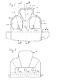
- the sliver guide 1 shown in FIGS. 1 to 5 serves for feeding one or two slivers, rovings or slivers 2, 3 and 4 to a drafting system 5.
- the drafting system 5 consists of several pairs of rolls, wherein in FIG. 1 only the two pairs of rolls 6, 7 and 8, 9 are shown.
- the lower rollers 6, 8 are driven lower rollers 6 and 8 , to each of which a top roller 7 and 9 is pressed.
- the lower rollers 6, 8 are formed as a sub-cylinder passing through in the machine longitudinal direction.
- the Lunten 2, 3, 4 are fed to the drafting 5 in the fiber transport direction A and warped to their desired fineness. It can be provided in a manner not shown, the drafting 5 downstream of a pair of output rollers downstream of a compacting device in which the Lunten 2, 3, 4 compacted in compacting zones and compacted. Following this, the finished warped fiber bundles are fed to a common twist element.
- the sliver guide 1 is fastened with a clamping device 10 on a slotted guide rail 11.
- the Lunten concernssschiene 11 can be moved transversely to the fiber transport direction A in the direction of arrow B back and forth.
- the traversing movement B serves to extend the service life of the upper rollers 7 and 9 provided with elastic covers.
- the essential parts of the sliver guide 1 are three guide funnels 12, 13 and 14.
- Each guide funnel 12, 13 and 14 has an inlet opening 121, 131, 141 and tapers in the fiber transport direction A funnel-shaped up to an outlet opening 122, 132, 142nd
- the advantage of the Lunten concernss 1 with three guide funnels 12, 13 and 14 is that the Lunten researching 1 can be used both for the production of false twist as well as for the production of single yarn.
- the Lunten researching 1 need not be exchanged or adjusted when changing from false twist to single yarn.
- the two guide funnels 12 and 14 are used to simultaneously supply the Lunten 2 and 4 the drafting 5.
- the two Lunten 2 and 4 are the nip 15 of the Input roller pair 6, 7 of the drafting system 5 through the two outlet openings 122 and 142 of the guide funnel 12 and 14 spaced supplied to each other.
- the Lunten 2 and 4 remain spaced when passing through the drafting 5 and are warped separately from each other to the desired fineness.
- the two warped Lunten 2 and 4 are then fed to a common twist element and twisted to a false twist.
- no fuse 3 is supplied, that is, the guide funnel 13 remains unused.
- the slivers 2 and 4 need to be removed from the guide funnels 12 and 14, and a new sliver 3 inserted into the middle guide funnel 13.
- the sliver 3 is fed to the nip 15 centrally through the outlet opening 132. In this case, the guide funnels 12 and 14 remain unused.
- Lunten concernsschiene 11 more Lunten concerns 1 are usually arranged at a distance of the pitch of the textile machine side by side.
- the Luntencetschiene is connected at a central location with a drive which generates the traversing movement B, thereby moving all Lunten concerns 1 synchronously transversely to the fiber transport direction A.
- the space at the adjacent drafting 5 are very cramped. It is therefore not possible to use a known triple-lunts leader.
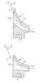
- the sliver guide 1 is therefore designed so that the guide funnels 12, 13, 14 are at least partially at different heights. It is preferably provided that the outlet openings 122, 132, 142 of the guide funnels 12, 13, 14 are at a height, so that in the transfer of the sliver 2, 3, 4 from the leader 1 in the nip 15 of the pair of input rollers 6, 7 are the same Conditions exist.
- the inlet opening 131 of the guide funnel 13 for the central sliver 3 is higher than the inlet openings 121 and 141 with respect to the clamping line 15 or with respect to the stretching field plane.
- the staggered arrangement of the inlet opening 131 allows a more compact construction of the sliver guide 1 with a reduced distance the guide funnel 12 and 14.
- the width of the Lunten concernss 1 transverse to the fiber transport direction A can thereby be chosen so small that the Lunten réelle 1 in textile machines each, in particular, of course small pitch can be used.
- the arrangement of the guide funnels 12, 13, 14 shows an advantageous embodiment.
- the height positions of the guide funnels 12, 13, 14 with respect to the nip 15 can also be chosen differently depending on the requirements.
- the Luntenraising 1 are required in relatively large numbers, it is advantageous for a rational production, when the Luntenraising 1 with all three guide funnels 12, 13, 14 is made in one piece as an injection molded part.
- the clamping device 10 is integrally formed on the Luntennian 1.
Landscapes
- Engineering & Computer Science (AREA)
- Mechanical Engineering (AREA)
- Textile Engineering (AREA)
- Spinning Or Twisting Of Yarns (AREA)
Applications Claiming Priority (1)
| Application Number | Priority Date | Filing Date | Title |
|---|---|---|---|
| DE200610053529 DE102006053529A1 (de) | 2006-11-08 | 2006-11-08 | Luntenführer für ein Streckwerk |
Publications (2)
| Publication Number | Publication Date |
|---|---|
| EP1921184A2 true EP1921184A2 (fr) | 2008-05-14 |
| EP1921184A3 EP1921184A3 (fr) | 2009-06-17 |
Family
ID=39059396
Family Applications (1)
| Application Number | Title | Priority Date | Filing Date |
|---|---|---|---|
| EP07019533A Withdrawn EP1921184A3 (fr) | 2006-11-08 | 2007-10-05 | Guide-mèche pour un banc d'étirage |
Country Status (3)
| Country | Link |
|---|---|
| EP (1) | EP1921184A3 (fr) |
| CN (1) | CN101177809B (fr) |
| DE (1) | DE102006053529A1 (fr) |
Cited By (2)
| Publication number | Priority date | Publication date | Assignee | Title |
|---|---|---|---|---|
| CN105155062A (zh) * | 2015-08-26 | 2015-12-16 | 经纬纺织机械股份有限公司 | 一种环锭细纱机上至少具有三根粗纱的喂入式导引装置 |
| CN113308770A (zh) * | 2021-07-01 | 2021-08-27 | 天津宏大纺织科技有限公司 | 一种粗纱紧密纺集束器 |
Families Citing this family (2)
| Publication number | Priority date | Publication date | Assignee | Title |
|---|---|---|---|---|
| CN102797081A (zh) * | 2012-08-30 | 2012-11-28 | 南通大学 | 双纱喂入隔距可调式喇叭口装置 |
| CN103981598A (zh) * | 2014-05-14 | 2014-08-13 | 浙江华孚色纺有限公司 | 一种赛络纺色纺段彩包芯纱细纱机装置及纺纱工艺 |
Family Cites Families (6)
| Publication number | Priority date | Publication date | Assignee | Title |
|---|---|---|---|---|
| BE372915A (fr) * | 1929-08-23 | |||
| US3020697A (en) * | 1958-11-07 | 1962-02-13 | Callaway Mills Co | Method and apparatus for producing multi-colored single yarn in simulation of ply yarn |
| CS277008B6 (en) * | 1987-06-24 | 1992-11-18 | Schubert & Salzer Maschinen | Apparatus for stable fiber sliver automatic feeding |
| DE59310302D1 (de) * | 1992-07-01 | 2002-10-10 | Rieter Ingolstadt Spinnerei | Vorrichtung zum Offenend-Spinnen |
| DE19717836A1 (de) * | 1997-04-26 | 1998-10-29 | Rieter Ag Maschf | Spinnmaschine mit Einlauftrichtern am Streckwerk |
| CN2761636Y (zh) * | 2004-12-28 | 2006-03-01 | 上海纺织机械总厂 | 一种防止棉条在输送过程中发生翻转的装置 |
-
2006
- 2006-11-08 DE DE200610053529 patent/DE102006053529A1/de not_active Withdrawn
-
2007
- 2007-10-05 EP EP07019533A patent/EP1921184A3/fr not_active Withdrawn
- 2007-11-08 CN CN2007101695101A patent/CN101177809B/zh not_active Expired - Fee Related
Cited By (3)
| Publication number | Priority date | Publication date | Assignee | Title |
|---|---|---|---|---|
| CN105155062A (zh) * | 2015-08-26 | 2015-12-16 | 经纬纺织机械股份有限公司 | 一种环锭细纱机上至少具有三根粗纱的喂入式导引装置 |
| CN105155062B (zh) * | 2015-08-26 | 2023-08-22 | 经纬智能纺织机械有限公司 | 一种环锭细纱机上至少具有三根粗纱的喂入式导引装置 |
| CN113308770A (zh) * | 2021-07-01 | 2021-08-27 | 天津宏大纺织科技有限公司 | 一种粗纱紧密纺集束器 |
Also Published As
| Publication number | Publication date |
|---|---|
| CN101177809B (zh) | 2011-06-08 |
| EP1921184A3 (fr) | 2009-06-17 |
| CN101177809A (zh) | 2008-05-14 |
| DE102006053529A1 (de) | 2008-05-15 |
Similar Documents
| Publication | Publication Date | Title |
|---|---|---|
| DE4447969B4 (de) | Spinnmaschine mit Saugluftleitmitteln zur Faserverband-Kondensation | |
| DE553975C (de) | Kegelfoermiger Bandtrichter fuer Streckwerke | |
| DE10236450A1 (de) | Spinnmaschine mit einem Mehrstufen-Verdichtungs-Streckwerk | |
| DE112008001937B4 (de) | Verzugseinheit für Strickmaschine | |
| EP2813604B1 (fr) | Filière et poste de filage d'un métier à filer à jet d'air en étant équipé | |
| EP1921184A2 (fr) | Guide-mèche pour un banc d'étirage | |
| WO1981003501A1 (fr) | Metier a filer, de preference metier continu a anneau | |
| EP0893519B1 (fr) | Condenseur de mèche dans un dispositif d'étirage d'une machine de filature | |
| DE102004026519A1 (de) | Vorrichtung an einer Spinnmaschine zum Verstrecken und Verdichten eines Stapelfaserverbandes | |
| DE102007003158A1 (de) | Streckwerks-Anordnung | |
| DE102007003525A1 (de) | Saugkanal für eine Faserbündelungseinrichtung | |
| DE102004042830B9 (de) | Vorrichtung zum Herstellen von Scheinzwirn | |
| DE10154127A1 (de) | Vorrichtung an einer Spinnmaschine zum Verdichten eines Faserverbandes | |
| WO2005028720A1 (fr) | Systeme de condensation mecanique d'un ensemble de fibres | |
| EP3688209B1 (fr) | Dispositif condenseur | |
| DE19733614A1 (de) | Absaugeinrichtung am Streckwerk einer Spinnmaschine | |
| DE102007063263A1 (de) | Saugkanal für eine Faserbündelungseinrichtung | |
| CH711154A1 (de) | Variabler Käfig für ein Druckwalzenpaar eines Streckwerks. | |
| EP3741889B1 (fr) | Guide condenseur pour un métier à filer, banc d'étirage pourvu du guide condenseur et procédé de fonctionnement du guide condenseur | |
| DE102004062796A1 (de) | Unterdruckkanal für Faserbündelungseinrichtungen einer Spinnmaschine | |
| DE102019128326A1 (de) | Verdichtungsvorrichtung für ein Streckwerk einer Spinnmaschine sowie Streckwerk für eine Verdichtungsvorrichtung | |
| DE102007006924A1 (de) | Vorrichtung zum Herstellen eines Scheinzwirnes | |
| CH699523A2 (de) | Streckwerk für den Verzug von Vorgarn. | |
| DE102016106207A1 (de) | Saugkörper für eine pneumatisch arbeitende Faserverdichtungseinrichtung sowie damit ausgestattete Spinnereimaschine | |
| EP1848848A1 (fr) | Guidage de courroie inferieure pour banc d'etirage a double courroie |
Legal Events
| Date | Code | Title | Description |
|---|---|---|---|
| PUAI | Public reference made under article 153(3) epc to a published international application that has entered the european phase |
Free format text: ORIGINAL CODE: 0009012 |
|
| AK | Designated contracting states |
Kind code of ref document: A2 Designated state(s): AT BE BG CH CY CZ DE DK EE ES FI FR GB GR HU IE IS IT LI LT LU LV MC MT NL PL PT RO SE SI SK TR |
|
| AX | Request for extension of the european patent |
Extension state: AL BA HR MK RS |
|
| PUAL | Search report despatched |
Free format text: ORIGINAL CODE: 0009013 |
|
| AK | Designated contracting states |
Kind code of ref document: A3 Designated state(s): AT BE BG CH CY CZ DE DK EE ES FI FR GB GR HU IE IS IT LI LT LU LV MC MT NL PL PT RO SE SI SK TR |
|
| AX | Request for extension of the european patent |
Extension state: AL BA HR MK RS |
|
| 17P | Request for examination filed |
Effective date: 20090807 |
|
| AKX | Designation fees paid |
Designated state(s): CH DE ES LI TR |
|
| STAA | Information on the status of an ep patent application or granted ep patent |
Free format text: STATUS: THE APPLICATION IS DEEMED TO BE WITHDRAWN |
|
| 18D | Application deemed to be withdrawn |
Effective date: 20100501 |