EP2813604B1 - Filière et poste de filage d'un métier à filer à jet d'air en étant équipé - Google Patents
Filière et poste de filage d'un métier à filer à jet d'air en étant équipé Download PDFInfo
- Publication number
- EP2813604B1 EP2813604B1 EP14001936.5A EP14001936A EP2813604B1 EP 2813604 B1 EP2813604 B1 EP 2813604B1 EP 14001936 A EP14001936 A EP 14001936A EP 2813604 B1 EP2813604 B1 EP 2813604B1
- Authority
- EP
- European Patent Office
- Prior art keywords
- attachment
- spinning
- roller
- surface section
- transport
- Prior art date
- Legal status (The legal status is an assumption and is not a legal conclusion. Google has not performed a legal analysis and makes no representation as to the accuracy of the status listed.)
- Active
Links
Images




Classifications
-
- D—TEXTILES; PAPER
- D01—NATURAL OR MAN-MADE THREADS OR FIBRES; SPINNING
- D01H—SPINNING OR TWISTING
- D01H4/00—Open-end spinning machines or arrangements for imparting twist to independently moving fibres separated from slivers; Piecing arrangements therefor; Covering endless core threads with fibres by open-end spinning techniques
- D01H4/02—Open-end spinning machines or arrangements for imparting twist to independently moving fibres separated from slivers; Piecing arrangements therefor; Covering endless core threads with fibres by open-end spinning techniques imparting twist by a fluid, e.g. air vortex
-
- D—TEXTILES; PAPER
- D01—NATURAL OR MAN-MADE THREADS OR FIBRES; SPINNING
- D01H—SPINNING OR TWISTING
- D01H1/00—Spinning or twisting machines in which the product is wound-up continuously
- D01H1/11—Spinning by false-twisting
- D01H1/115—Spinning by false-twisting using pneumatic means
-
- D—TEXTILES; PAPER
- D01—NATURAL OR MAN-MADE THREADS OR FIBRES; SPINNING
- D01H—SPINNING OR TWISTING
- D01H7/00—Spinning or twisting arrangements
- D01H7/92—Spinning or twisting arrangements for imparting transient twist, i.e. false twist
Definitions
- the present invention relates to a spinneret for an air spinning machine, which serves to produce a yarn from a fiber structure, wherein the spinneret has a base body with an internal swirl chamber, wherein the spinneret has an inlet opening for the incoming during operation of the air spinning machine in a transport direction in the swirl chamber fiber structure wherein between the inlet opening and the swirl chamber, a fiber guide channel for guiding the entering into the inlet fiber bundle is present, wherein the spinneret has at least partially extending into the vortex chamber Garn avoirselement with an inlet mouth and a subsequent in the transport direction take-off channel for the yarn, and wherein the spinneret has air nozzles directed into the swirl chamber, which open into the swirl chamber in the region of a wall surrounding the swirl chamber.
- a spinning station of an air-spinning machine is proposed.
- Air-jet spinning machines with correspondingly equipped spinnerets or spinning stations are known in the art (see, for example, US Pat DE 40 36 119 C2 ) and serve to produce a yarn from an elongated fiber structure.
- the outer fibers of the fiber composite are wound around the inner core fibers in the area of the aforementioned inlet mouth of the yarn formation element by means of a vortex air flow generated by the air nozzles within the vortex chamber and finally form the binder fibers which determine the desired strength of the yarn.
- This creates a yarn with a true rotation, which finally dissipated via the discharge channel from the vortex chamber and z. B. can be wound on a spool.
- the term yarn generally means a fiber structure in which at least some of the fibers are wound around an inner core.
- a yarn is included in the traditional sense, which can be processed into a fabric, for example with the aid of a weaving machine.
- the invention also relates to air spinning machines, with the help of so-called roving (other name: Lunte) can be produced.
- roving other name: Lunte
- This type of yarn is characterized by the fact that, despite a certain strength, which is sufficient to transport the yarn to a subsequent textile machine, it is still delayable.
- the roving can thus with the help of a defaulting device, z.
- a roving processing textile machine such as a ring spinning machine, are warped before it is finally spun.
- the rotation produced in the region of the yarn formation element does not propagate outwardly beyond the inlet opening in the direction of transport of the yarn or fiber composite. In other words, it should therefore be ensured that the fibers of the fiber composite retain their original orientation prior to contact with the vortex air flow and only receive the corresponding rotation within the vortex chamber. If the rotation were to propagate counter to the transport direction, the associated reverse rotation of the fiber composite would inevitably lead to a reduction in the desired binder fibers or to a reduced resilience of the fiber composite in the region of a distortion device arranged upstream of the vortex chamber.
- the spinneret can usually only for a certain Faser notion type or fibers with certain Length are used, since the distance between the fiber guide element and one of the spinneret upstream delivery roller pair must be tuned to a certain fiber length usually.
- JP 2009 091684 A a likewise designed as an insert fiber guide element, which is characterized in that a the output rollers of the spinneret upstream drafting facing outer surface concavely curved and thus the contour of one of said output rollers is adjusted.
- the object of the present invention is to propose a spinneret or a spinning station equipped therewith for an air-spinning machine which overcomes this disadvantage.
- the spinneret in the region of the inlet opening has a detachably attached to the base attachment, wherein the adjoining the inlet fiber guide channel is at least partially formed by a channel portion of the essay.
- the fiber guide channel is at least not formed exclusively by a rigidly connected to the main body fiber guide element.
- an essay is available, which can be easily replaced depending on the type or length of the fibers to be processed.
- the attachment finally results in a fiber guide channel with correspondingly adapted to the fiber structure length or shape.
- the article preferably has a base body with an opening formed as a fiber guide channel (section), for example in the form of a bore extending from one of the base body
- the spinneret side facing away from the spinneret may extend in the direction of a spinneret facing side.
- the attachment is connected to the main body of the spinneret by means of one or more magnets.
- the magnets can in this case be attached either to the main body or to the attachment, whereby magnets can also be provided on both components.
- the base body also has a channel section which, viewed in the transport direction, adjoins the channel section of the attachment and together with it forms the fiber guide channel.
- the channel section of the main body forms in this case an end portion of the fiber guide channel (seen in the transport direction of the fiber composite), which may be formed either as an opening of the body or by a separate, preferably rigidly connected to the body, fiber guide element may be formed.
- the attachment rests at least partially positively against the base body.
- the attachment may, for example, have a surface facing the base body, which is curved concavely with respect to the base body (in which case the base body should have a correspondingly convexly shaped counter surface on which the attachment comes to rest).
- the attachment has a contact surface for the positive engagement with the base body, which is channel-shaped and, for example, has three planar surface portions, which merge into each other at an obtuse angle.
- the base body has a wedge-shaped surface section (possibly with a flattened tip), which preferably rests flat against the abutment surface of the attachment.
- the attachment comprises a base member and an insert connected to a base member.
- the insert which forms or surrounds the guide channel or at least a part of the same, from a particularly wear-resistant material.
- the insert can be detachably connected to the base element or can also be fixedly connected (eg by gluing).
- the insert is preferably located in a corresponding receiving recess, for example a bore, of the base element, with any magnets present being advantageously connected to the base element.
- the insert is in contact with a fiber guiding element of the main body of the spinneret, wherein the insert and the fiber guiding element together at least partially delimit the fiber guiding channel.
- the fiber guide element forms a base portion of the fiber guide channel, which opens into the swirl chamber.
- the attachment advantageously adjoins the fiber guiding element counter to the direction of transport and, together with the latter, forms the fiber guiding channel whose length and geometry can finally be varied by the choice of the respective attachment depending on the fiber structure.
- the attachment has at least one concave surface section extending perpendicularly to the transport direction.
- this surface section adjoins a first (preferably driven) roller of the delivery roller pair (eg, a drafting device) upstream of the spinneret, a gap results between the attachment and the aforementioned roller.
- this gap can be chosen as small as possible in order to prevent unfavorable air currents in the air To avoid the area of the inlet opening of the spinneret.
- the surface section is concentric with the lateral surface of the first roller.
- the concave surface section is preferably formed following the contour of a cylinder jacket, since the spinneret is usually arranged directly upstream of the already mentioned pair of delivery rollers (in the transport direction). If a roller of the delivery roller pair is now placed as close as possible to the attachment, the result is an annular section-shaped gap, the advantages of which will be discussed in more detail in the following description.
- the insert has a length L 1 extending in the transport direction, the amount of which lies between 1 mm and 100 mm, preferably between 2 mm and 50 mm, particularly preferably between 4 mm and 25 mm. If the length is in one of these ranges, the spinneret can be used by selecting a suitable attachment for processing a variety of fiber bundles (i.e., fibers of various staple lengths).
- the fiber guide channel has a length L2 extending in the transport direction (of the fiber composite), the amount of which lies between 6 mm and 110 mm, preferably between 7 mm and 60 mm, particularly preferably between 9 mm and 30 mm.
- the spinning unit of an air-spinning machine is characterized in that it comprises a spinneret according to the previous description and a pair of delivery rollers arranged upstream of the spinneret in the transport direction.
- the pair of delivery rollers may, for example, be part of a drafting arrangement upstream of the spinneret which, during operation of the spinning station, effects the uniformization of the supplied fiber-composite by stretching it.
- the spinning station can Having a deduction means downstream of the spinneret in the transport direction for the yarn produced (eg., A pair of take-off rollers) and a winding device for winding the yarn.
- the attachment has at least one concave surface section extending perpendicularly to the transport direction, wherein the concave surface section extends adjacent to a lateral surface of a first roller of the delivery roller pair.
- said surface section can nestle as close as possible to the first roller, so that the gap between the first roller and the attachment can be minimized.
- Such a small gap will cause the drag air flow generated by the first roll (which is preferably a driven roll, which may, for example, have a roughed surface) (ie, the air flow generated by the rotation of the roll in the surface region the same arises) as low as possible.
- the first roller does not produce any desired air flow in the region of the inlet opening of the spinneret opposite air flow. Rather, in the region of the inlet opening, an air flow directed into the fiber guide channel is desired in order to suck the fiber structure and in particular short or projecting fibers into the vortex chamber (the necessary negative pressure in the region of the inlet opening being due to the Venturi effect by the air nozzles of the spinneret generated air flow is generated).
- the concave surface portion and the lateral surface of the first roller are concentric. This results in a particularly large gap between the first roller and said surface portion, so that a drag flow of the first roller through the essay can be "peeled off” as it were.
- the concave surface section has a width B1 in a direction perpendicular to the transport direction, that the lateral surface of the first roller adjacent to the concave surface section has a width B2, and that the ratio between B1 and B2 has a value, the amount of which is between 0.2 and 5, preferably between 0.5 and 2, more preferably between 0.8 and 1.25.
- B1 is approximately equal to B2, so that the entire roll is covered by the attachment over a certain peripheral area.
- the attachment has a second surface portion adjacent the concave surface portion, the second surface portion being adjacent to a surface area of a second roller of the pair of delivery rolls.
- the attachment preferably has in a side view (i.e., facing the faces of the rollers) a tapered contour facing the delivery roller pair (which tip area may also be flattened) and thus has a roof-shaped surface.
- the second surface portion is at least largely planar.
- a gap is created between the second roller and the attachment which deviates from the annular segment-shaped gap between the first roller and the attachment (seen in cross-section).
- this prevents the formation of an air flow which is directed outward from the inlet opening of the spinneret in the direction of rotation of the second roller.
- Such an air flow would compete with the airflow directed into the vortex chamber and adversely affect the desired flow conditions in this area.
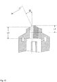
- the normal of the plane-shaped region of the second surface section encloses an angle ⁇ with a longitudinal axis of the fiber guide channel extending in the transport direction, the magnitude of which is between 0 ° and 60 °, preferably between 25 ° and 55 °, particularly preferably between 30 ° ° and 50 °, lies.
- the normal of the second surface section is directed approximately in the direction of the axis of rotation of the second roller. This finally results in a side view of the spinneret (with a view of the end faces of the first and second rollers) a substantially triangular space, which may extend over the width of the two rollers.
- the distance A1 between the first roller and the concave surface portion is smaller than the distance A2 between the second Roller and the second surface section.
- the distance A1 between the first roller and the concave surface portion is smaller than the distance A2 between the second Roller and the second surface section.
- the generation of a negative pressure by the first roller is usually desirable in order to force the parallel to the axes of rotation of the rollers of the delivery roller pair and finally opening into the inlet opening of the spinneret air flow, as this is said compacting of the fiber composite is effected.
- the distance A1 has an amount which is between 0.1 mm and 5 mm, preferably between 0.1 mm and 3 mm, particularly preferably between 0.2 mm and 2 mm. This results in the described narrow gap between attachment and first roller, which can extend in a side view of the spinneret (view of the end faces of the rollers), for example over a length which preferably corresponds to 1/10 to 1/4 of the circumference of the first roller.
- the distance A2 has an amount which is between 0.5 mm and 10 mm, preferably between 1 mm and 8 mm, particularly preferably between 2 mm and 6 mm. If the distance is within the ranges mentioned, then a negative effect on the prevailing in the region of the inlet opening Air flow by the rotation of the second roller almost impossible or at least minimized.
- the intermediate surface in this case has a width B3 extending perpendicular to the transport direction, wherein the ratio between B2 and B3 preferably has a value whose amount is between 0.2 and 5, preferably between 0.5 and 2, particularly preferably between 0.8 and 1 , 25, is located.
- the intermediate surface has a perpendicular to the transport direction and perpendicular to the width B3 extending height H, the amount between 0 mm and 12 mm, preferably between 0 mm and 8 mm, particularly preferably between 0 mm and 6 mm (where a height of 0 mm means that the attachment is tapered and the concave surface portion passes directly into the second surface portion).
- the above values ensure that the two rolls of the delivery roller pair form a channel with the attachment, which preferably extends over the entire width of the attachment or the rollers and which has a substantially triangular shape in a side view.
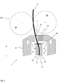
- FIG. 1 now shows a schematic view of a section of a trained as roving air spinning machine.
- the roving frame can comprise a drafting device 27, which is supplied with a fiber structure 3, for example in the form of a relined strip conveyor.
- the roving shown in principle comprises a spaced apart from the drafting 27 spinneret 1 with an internal swirl chamber 5, in which the fiber strand 3 or at least a portion of the fibers of the fiber composite 3 is provided with a protective rotation (the exact operation of the spinneret 1 is hereinafter described in more detail).
- the roving machine may include a take-off roller pair 28 and a winding device 29 connected downstream of the take-off roller pair 28 (also shown schematically) for the yarn 2 produced.
- the inventive device does not necessarily have a drafting device 27, as shown in FIG. Also, the take-off roller pair 28 is not essential.
- the roving machine now works according to a special air spinning process.
- the fiber structure 3 is guided in a transport direction T via an inlet opening 6 of a (preferably designed as a separate component) fiber guide element 18 in the swirl chamber 5 of the spinneret 1.
- a protective rotation ie at least a portion of the fibers of the fiber composite 3 is characterized by an air flow through appropriately placed air nozzle 11 (see, for example FIG. 2 ) is detected.
- a part of the fibers is in this case pulled out of the fiber structure 3 at least a little bit and wound around the tip of a protruding into the swirl chamber 5 Garn Strukturselements 8.
- the individual air nozzles 11 are in this case arranged rotationally symmetrical to one another.
- the air nozzles 11 each have a flow direction, which is aligned in the direction of a wall 12 surrounding the swirl chamber 5, so that the air flow generated at least largely helically between the outer surface of Garnsentelements 8 and the Wall 12 of the vortex chamber 5 extends.
- the fibers of the fiber composite 3 are drawn off from the swirl chamber 5 via an inlet mouth 9 of the yarn formation element 8 and a discharge channel 10 arranged inside the yarn formation element 8 and adjoining the inlet mouth 9.
- the free fiber ends 30 are drawn on a spiral path in the direction of the inlet mouth 9 and loop as Umwindefasern to the centrally extending core fibers - resulting in a desired protective rotation having yarn 2 (which is usually referred to as roving or sliver).
- the yarn 2 has by the only partial rotation of the fibers a residual delay, which is essential for the further processing of the yarn 2 in a subsequent spinning machine, such as a ring spinning machine.
- conventional air-spinning devices impart such a strong rotation to the fiber structure 3 that the necessary distortion following the yarn production is no longer possible. This is also desirable in this case, since conventional air spinning machines are designed to produce a finished yarn 2, which should usually be characterized by a high strength.
- the invention relates to both air roving and air spinning in the conventional sense.
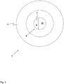
- spinneret 1 is from the Figures 2 and 3 apparent (where it is at FIG. 3 around a top view of in FIG. 2 shown spinneret 1 is).
- this generally has a vortex chamber 5 surrounding the base body 4, wherein the vortex chamber 5 a fiber guide channel 7 of the Fiber guide element 18 connects.
- the fiber guide channel 7 serves to guide the fiber composite 3 during its suction into the swirl chamber 5 (whereby the necessary negative pressure is created by the air flow generated by the air nozzles 11).
- the position of the fiber guide channel 7, which is not aligned with the discharge channel 10, prevents the protective rotation from propagating from the inlet mouth 9 of the yarn formation element 8 in the direction of the upstream pair of delivery rolls 20, since this has a negative effect on the desired protection rotation distribution (or twist distribution in the case of a conventional air spinning machine) in the region of the inlet opening 6 would result.
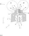
- the inventive fiber guide channel 7 now characterized by the fact that it is at least partially formed by a separate attachment 13 which is detachably connected to the main body 4 of the spinneret 1.
- the connection between attachment 13 and main body 4 is realized in that the base body 4 or (as in FIG. 6 shown) of the attachment 13 is provided with one or more magnets 15 to ensure the necessary adhesive force between attachment 13 and body 4.
- the fiber guide channel 7 is formed by two, preferably co-linear, channel sections 14, wherein a first channel section 14 within the main body 4 and the fiber guide element 18 connected thereto and a second channel section 14 within the attachment 13 extends ,
- the attachment 13 consists of at least two interconnected individual parts, namely a base element 16 and an insert 17 forming said channel section 14.
- the attachment 13 consists of at least two interconnected individual parts, namely a base element 16 and an insert 17 forming said channel section 14.
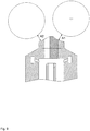
- FIGS. 7 and 8th Further advantageous features of the article 13 are in particular from the FIGS. 7 and 8th can be seen, in both figures, the same combination of spinneret 1 and article 13 can be seen (both versions differ only by a possibly be provided and in FIG. 8 shown positive connection in the region of the connecting surface between the attachment and the base element, which can ensure the correct position of the attachment with respect to the base body, wherein the positive connection z. B. could be realized by a tongue and groove connection 32).
- the first roller 22 and in FIG. 8 omitted the second roller 24, wherein the corresponding spinning station 26 should of course have both rollers 22, 24.
- the attachment 13 has a concave surface section 19 assigned to the first roller 22 and a (preferably planar) second surface portion 23 which is associated with the second roller 24.
- both surface sections can also be connected by an intermediate surface 25 whose surface can run, for example, perpendicular to the longitudinal axis of the discharge channel 10 (as in FIG FIG. 6
- such an intermediate surface 25 is not necessarily necessary, so that said surface portions 19, 23 can also merge directly into one another).
- the surface of the second roller 22 should preferably be designed to be relatively smooth, so that in this area a corresponding entraining air flow can be minimized (such an air flow would have a negative effect on the remaining air flows that are forming).
- FIG. 11 a section of an inventive spinneret 1 in a side view, from which a further advantageous embodiment of the present invention will become apparent.
- the main body 4 of the spinneret 1 and the attachment 13 in such a way that they abut each other in a form-fitting manner.
- the mutually contacting surfaces of the base body 4 and attachment 13 can thereby be flat or even configured (the surface of said surfaces were in this case perpendicular to the sheet plane, ie parallel to the axis of rotation of the first roller 22).
- the already mentioned magnets 15 ensure a certain positional stability of the attachment 13 relative to the base body 4.
Landscapes
- Engineering & Computer Science (AREA)
- Mechanical Engineering (AREA)
- Textile Engineering (AREA)
- Spinning Or Twisting Of Yarns (AREA)
- Spinning Methods And Devices For Manufacturing Artificial Fibers (AREA)
Claims (15)
- Filière destinée à une machine à filer à air qui est utilisée pour produire un fil (2) constitué d'un assemblage de fibres (3),• la filière (1) possédant un corps de base (4) pourvu d'une chambre de turbulence interne (5),• la filière (1) possédant une ouverture d'entrée (6) destiné à l'assemble de fibres (3) entrant dans la chambre de turbulence (5) dans une direction de transport pendant le fonctionnement de la machine à filer à air,• un conduit de guidage de fibres (7) destiné à guider l'assemblage de fibres (3) entrant dans l'ouverture étant prévu entre l'ouverture d'entrée et la chambre de turbulence (5),• la filière (1) possédant un élément de formation de fil 8), qui s'étend au moins partiellement jusque dans la chambre de turbulence (5) et qui comporte un orifice d'entrée (9) suivi d'un conduit de sortie, par référence à la direction de transport (10), qui est destiné au fil (2),• la filière (1) comportant des buses d'air (11) qui sont orientées jusque dans la chambre de turbulence (5) et qui débouchent dans la chambre de turbulence (5) au niveau de la paroi (12) entourant la chambre de turbulence (5),• la filière (1) possédant au niveau de l'ouverture d'entrée (6) un chapeau (13) fixé de manière amovible sur le corps de base (4), et• le conduit de guidage de fibres (7), qui se raccorde à l'ouverture d'entrée (6), étant formé par une partie formant conduit (14) du chapeau (13),caractérisée en ce que
le corps de base (4) possède également une partie formant conduit (14) qui se raccorde, par référence à la direction de transport, à la partie formant conduit (14) du chapeau (13) et forme conjointement avec celui-ci le conduit de guidage de fibres (7). - Filière selon la revendication précédente, caractérisée en ce que le chapeau est fixé de manière amovible au corps de base (4) à l'aide d'au moins un aimant.
- Filière selon l'une des revendications précédentes, caractérisée en ce que le chapeau (13) est en appui au moins par endroits par complémentarité de formes sur le corps de base (4) et/ou en ce qu'une liaison par friction est réalisée entre le chapeau (13) et le corps de base (4), laquelle liaison par friction s'oppose au déplacement du chapeau (13) par rapport au corps de base (4) au moins en direction d'un axe spatial.
- Filière selon l'une des revendications précédentes, caractérisée en ce que le chapeau (13) comprend un élément de base (16) et un insert (17) relié à l'élément de base (16), et en ce que l'insert (17) est de préférence en contact avec un élément de guidage de fibres (18) du corps de base (4) de la filière (1), l'insert (17) et l'élément de guidage de fibres (18) délimitant conjointement, au moins partiellement, le conduit de guidage de fibres (7).
- Filière selon l'une des revendications précédentes, caractérisée en ce que le chapeau (13) comporte au moins une partie de surface concave (19) qui s'étend perpendiculairement à la direction de transport et qui est conçue de préférence pour suivre le contour d'une enveloppe cylindrique.
- Filière selon la revendication 4 ou selon les revendications 4 et 5, caractérisée en ce que l'insert (17) a dans la direction de transport une longueur L1 dont la valeur est comprise entre 1 mm et 100 mm, de préférence entre 2 mm et 50 mm, de façon particulièrement préférée entre 4 mm et 25 mm.
- Filière selon l'une des revendications précédentes, caractérisée en ce que le conduit de guidage de fibres (7) a dans la direction de transport une longueur L2 dont la valeur est comprise entre 6 mm et 110 mm, de préférence entre 7 mm et 60 mm, de façon particulièrement préférée entre 9 mm et 30 mm.
- Filière d'une machine à filer à air, la position de filage comprenant au moins une filière (1) selon l'une ou plusieurs des revendications précédentes, et une filière (1) dans la direction de transport est disposé paire de rouleaux de sortie en amont (20).
- Station de filage selon la revendication précédente, caractérisée en ce que le chapeau (13) comporte au moins une partie de surface concave (19), selon la revendication 5, qui s'étend perpendiculairement à la direction de transport, la partie de surface concave (19) étend adjacente à une surface d'enveloppe (21) d'un premier cylindre (22) de la paire de cylindres détacheurs (20), et la partie de surface concave (19) du chapeau (13) et la surface d'enveloppe (21) du premier cylindre (22) s'étendant de préférence de manière concentrique.
- Station de filage selon la revendication précédente, caractérisée en ce que la partie de surface concave (19) a une largeur B1 dans une direction perpendiculaire à la direction de transport, en ce que la surface d'enveloppe (21) du premier cylindre (22) adjacent à la partie de surface concave (19) a une largeur B2 et en ce que le rapport entre B1 et B2 a une valeur comprise entre 0,2 et 5, de préférence entre 0,5 et 2, de manière particulièrement préférée entre 0,8 et 1,25.
- Station de filage selon la revendication 9 ou 10, caractérisée en ce que le chapeau (13) possède une seconde partie de surface (23) adjacente à la partie de surface concave (19), la seconde partie de surface (23) étant adjacente à une surface d'enveloppe (21) d'un second cylindre (24) de la paire de cylindres détacheurs (20) et la seconde partie de surface (23) étant de préférence, au moins pour la plus grande partie, plane.
- Station de filage selon la revendication précédente, caractérisée en ce que la normale (31) de la région plane de la seconde partie de surface (23) forme avec un axe longitudinal, s'étendant dans la direction de transport, du conduit de guidage de fibres un angle α dont la valeur est comprise entre 0 et 60°, de préférence entre 25° et 55°, et de manière particulièrement préférée entre 30° et 50°.
- Station de filage selon la revendication 11 ou 12, caractérisée en ce qu'une distance est ménagée entre le premier cylindre (22) et la partie de surface concave (19) et entre le second cylindre (24) et la seconde partie de surface (23) dans chaque cas prévu, la distance A1 entre le premier cylindre (22) et la partie de surface concave (19) étant inférieure à la distance A2 entre le second cylindre (24) et la seconde partie de surface (23).
- Station de filage selon la revendication précédente, caractérisée en ce que la distance A1 a une valeur qui est comprise entre 0,1 mm et 5 mm, de préférence entre 0,1 mm et 3 mm, de manière particulièrement préférée entre 0,2 mm et 2 mm et/ou en ce que la distance A2 a une valeur qui est comprise entre 0,5 mm et 10 mm, de préférence entre 1 mm et 8 mm, de façon particulièrement préférée entre 2 mm et 6 mm.
- Station de filage selon la revendication 10 et l'une des revendications 11 à 14, caractérisée en ce que la partie de surface concave (19) et la seconde partie de surface (23) sont reliées entre elles par une surface intermédiaire (25), la surface intermédiaire (25) ayant une largeur B3 perpendiculairement à la direction de transport, le rapport entre B2 et B3 ayant de préférence une valeur comprise entre 0,2 et 5, de préférence entre 0,5 et 2, de façon particulièrement préférée entre 0,8 et 1,25, et/ou la surface intermédiaire (25) ayant une hauteur H, perpendiculairement à la direction de transport et perpendiculairement à la largeur B3, dont la valeur est comprise entre 0 mm et 12 mm, de préférence entre 0 mm et 8 mm, de façon particulièrement préférée entre 0 mm et 6 mm.
Applications Claiming Priority (1)
| Application Number | Priority Date | Filing Date | Title |
|---|---|---|---|
| CH01121/13A CH708164A1 (de) | 2013-06-14 | 2013-06-14 | Spinndüse sowie damit ausgerüstete Spinnstelle einer Luftspinnmaschine. |
Publications (2)
| Publication Number | Publication Date |
|---|---|
| EP2813604A1 EP2813604A1 (fr) | 2014-12-17 |
| EP2813604B1 true EP2813604B1 (fr) | 2017-08-16 |
Family
ID=50897326
Family Applications (1)
| Application Number | Title | Priority Date | Filing Date |
|---|---|---|---|
| EP14001936.5A Active EP2813604B1 (fr) | 2013-06-14 | 2014-06-04 | Filière et poste de filage d'un métier à filer à jet d'air en étant équipé |
Country Status (5)
| Country | Link |
|---|---|
| US (1) | US9243352B2 (fr) |
| EP (1) | EP2813604B1 (fr) |
| JP (1) | JP6558879B2 (fr) |
| CN (1) | CN104233530B (fr) |
| CH (1) | CH708164A1 (fr) |
Families Citing this family (5)
| Publication number | Priority date | Publication date | Assignee | Title |
|---|---|---|---|---|
| DE102015117204A1 (de) * | 2015-10-08 | 2017-04-13 | Rieter Ingolstadt Gmbh | Verfahren zum Vorbereiten eines Garnendes zum Anspinnen an einer Rotorspinnvorrichtung einer Rotorspinnmaschine sowie Rotorspinnmaschine |
| IT201600070676A1 (it) * | 2016-07-07 | 2018-01-07 | Savio Macch Tessili Spa | Dispositivo di filatura di tipo air-jet |
| CH712663A1 (de) * | 2016-07-14 | 2018-01-15 | Rieter Ag Maschf | Verfahren zum Verarbeiten eines strangförmigen Faserverbands sowie Vorspinnmaschine. |
| DE102017116893A1 (de) * | 2016-07-28 | 2018-02-01 | Rieter Ingolstadt Gmbh | Fadenführungseinheit, Offenend-Spinnmaschine und Verfahren zum Betreiben einer Spinnstelle |
| JP2021042510A (ja) * | 2019-09-13 | 2021-03-18 | 村田機械株式会社 | 紡績ユニット、空気紡績装置、紡績機、及び紡績方法 |
Citations (1)
| Publication number | Priority date | Publication date | Assignee | Title |
|---|---|---|---|---|
| WO2011006580A1 (fr) * | 2009-07-17 | 2011-01-20 | Maschinenfabrik Rieter Ag | Elément pour dispositif de filature à tuyère à air |
Family Cites Families (16)
| Publication number | Priority date | Publication date | Assignee | Title |
|---|---|---|---|---|
| US3110950A (en) * | 1960-04-16 | 1963-11-19 | Kurashiki Rayon Co | Bulking nozzle for treating yarn |
| US3577720A (en) * | 1968-12-18 | 1971-05-04 | Natan Albertovich Zax | Device for twisting yarn |
| JPS61167031A (ja) * | 1985-01-14 | 1986-07-28 | Toyoda Autom Loom Works Ltd | 結束紡績用ノズル |
| DE3732708A1 (de) | 1987-01-15 | 1988-07-28 | Stahlecker Fritz | Luftduese fuer pneumatisches falschdrallspinnen mit einem aus wenigstens zwei teilstuecken gebildeten fadenkanal |
| DE4036119C2 (de) | 1989-11-14 | 1994-07-07 | Murata Machinery Ltd | Vorrichtung zur Herstellung gesponnener Fäden |
| DE4201573A1 (de) * | 1992-01-22 | 1993-07-29 | Schurr Stahlecker & Grill | Vorrichtung zum pneumatischen falschdrallspinnen |
| US6782685B2 (en) * | 2000-12-22 | 2004-08-31 | Maschinenfabrik Rieter Ag | Apparatus for producing a core spun yarn |
| US20020152739A1 (en) | 2000-12-22 | 2002-10-24 | Maschinenfabrik Rieter Ag | Spinning device |
| EP1335050B1 (fr) * | 2002-02-12 | 2008-07-16 | Maschinenfabrik Rieter Ag | Machine textile comprennant un canal pour alimenter des fibres et une surface pour guider des fibres |
| DE10335651B4 (de) * | 2003-07-29 | 2017-02-23 | Wilhelm Stahlecker Gmbh | Verfahren und Vorrichtung zum Wiederherstellen eines unterbrochenen Spinnvorganges |
| DE102005035049A1 (de) * | 2005-07-27 | 2007-02-01 | Saurer Gmbh & Co. Kg | Spinnvorrichtung zur Herstellung eines gesponnenen Fadens mittels eines umlaufenden Luftstroms |
| JP2009091684A (ja) * | 2007-10-05 | 2009-04-30 | Murata Mach Ltd | 紡績装置 |
| DE102008050874A1 (de) * | 2008-09-29 | 2010-04-01 | Wilhelm Stahlecker Gmbh | Luftdüsenspinnaggregat mit spindelförmigem Bauteil |
| US8464510B2 (en) * | 2009-07-16 | 2013-06-18 | Maschinenfabrik Rieter Ag | Air-jet spinning apparatus |
| JP2012102432A (ja) * | 2010-11-10 | 2012-05-31 | Murata Mach Ltd | 空気紡績装置、紡績ユニット及び空気紡績装置を用いた紡績方法 |
| DE102011053837A1 (de) * | 2011-09-21 | 2013-03-21 | Maschinenfabrik Rieter Ag | Spinnspitze für eine Hohlspindel einer Luftspinnmaschine |
-
2013
- 2013-06-14 CH CH01121/13A patent/CH708164A1/de not_active Application Discontinuation
-
2014
- 2014-06-04 EP EP14001936.5A patent/EP2813604B1/fr active Active
- 2014-06-13 CN CN201410262529.0A patent/CN104233530B/zh active Active
- 2014-06-13 US US14/303,960 patent/US9243352B2/en active Active
- 2014-06-16 JP JP2014123298A patent/JP6558879B2/ja active Active
Patent Citations (1)
| Publication number | Priority date | Publication date | Assignee | Title |
|---|---|---|---|---|
| WO2011006580A1 (fr) * | 2009-07-17 | 2011-01-20 | Maschinenfabrik Rieter Ag | Elément pour dispositif de filature à tuyère à air |
Also Published As
| Publication number | Publication date |
|---|---|
| JP2015001042A (ja) | 2015-01-05 |
| EP2813604A1 (fr) | 2014-12-17 |
| US20140366503A1 (en) | 2014-12-18 |
| CN104233530A (zh) | 2014-12-24 |
| CH708164A1 (de) | 2014-12-15 |
| US9243352B2 (en) | 2016-01-26 |
| JP6558879B2 (ja) | 2019-08-14 |
| CN104233530B (zh) | 2018-09-18 |
Similar Documents
| Publication | Publication Date | Title |
|---|---|---|
| EP2895646B1 (fr) | Poste de filage d'un métier à filer à jet d'air | |
| EP1529128A1 (fr) | Banc d'etirage destine a des machines a filer comportant un dispositif de serrage | |
| EP2511403B1 (fr) | Banc à broches pour la fabrication d'une mèche | |
| WO2014041412A2 (fr) | Poste de filage d'un banc à broches | |
| EP3449048A1 (fr) | Métier à filer à jet d'air et procédé de production d'un fil | |
| EP0947614A2 (fr) | Métier de filature avec un dispositif d'étirage pourvu d'un cylindre d'aspiration | |
| DE1904561B2 (de) | Faserzufuhreinrichtung | |
| EP2813604A1 (fr) | Filière et poste de filage d'un métier à filer à jet d'air en étant équipé | |
| DE69713733T2 (de) | Spinnvorrichtung | |
| EP2772572A9 (fr) | Poste de filage pour la fabrication d'un fil | |
| EP1335050B1 (fr) | Machine textile comprennant un canal pour alimenter des fibres et une surface pour guider des fibres | |
| EP2454403B1 (fr) | Machine à filer à jet d'air | |
| WO2015189674A1 (fr) | Buse de filage pour un métier à filer à jet d'air et métier à filer à jet d'air avec buse de filage correspondante | |
| EP3052683B1 (fr) | Poste de filage de machine à filer à jet d'air équipé avec un élément de guidage de fibres | |
| DE102007003525A1 (de) | Saugkanal für eine Faserbündelungseinrichtung | |
| EP1921184A2 (fr) | Guide-mèche pour un banc d'étirage | |
| DE102014112360A1 (de) | Garnbildungselement für eine Spinndüse einer Luftspinnmaschine, Luftspinnmaschine sowie Verfahren zum Betrieb einer solchen | |
| EP3688209B1 (fr) | Dispositif condenseur | |
| DE102004020984A1 (de) | Spinnmaschine mit einer Verdichtungseinrichtung | |
| DE102008011617A1 (de) | Pneumatische Stapelfaserspinnvorrichtung | |
| DE19608829A1 (de) | Saugwalze für Offenend-Spinnmaschinen | |
| EP3741889B1 (fr) | Guide condenseur pour un métier à filer, banc d'étirage pourvu du guide condenseur et procédé de fonctionnement du guide condenseur | |
| DE102012106781A1 (de) | Saugkörper für eine pneumatisch arbeitende Faserbündelungseinrichtung sowie damit ausgestattete Spinnereimaschine | |
| WO2014040912A1 (fr) | Poste de filage | |
| DE102016106207A1 (de) | Saugkörper für eine pneumatisch arbeitende Faserverdichtungseinrichtung sowie damit ausgestattete Spinnereimaschine |
Legal Events
| Date | Code | Title | Description |
|---|---|---|---|
| 17P | Request for examination filed |
Effective date: 20140604 |
|
| AK | Designated contracting states |
Kind code of ref document: A1 Designated state(s): AL AT BE BG CH CY CZ DE DK EE ES FI FR GB GR HR HU IE IS IT LI LT LU LV MC MK MT NL NO PL PT RO RS SE SI SK SM TR |
|
| AX | Request for extension of the european patent |
Extension state: BA ME |
|
| PUAI | Public reference made under article 153(3) epc to a published international application that has entered the european phase |
Free format text: ORIGINAL CODE: 0009012 |
|
| R17P | Request for examination filed (corrected) |
Effective date: 20150611 |
|
| RBV | Designated contracting states (corrected) |
Designated state(s): AL AT BE BG CH CY CZ DE DK EE ES FI FR GB GR HR HU IE IS IT LI LT LU LV MC MK MT NL NO PL PT RO RS SE SI SK SM TR |
|
| 17Q | First examination report despatched |
Effective date: 20160616 |
|
| GRAP | Despatch of communication of intention to grant a patent |
Free format text: ORIGINAL CODE: EPIDOSNIGR1 |
|
| INTG | Intention to grant announced |
Effective date: 20170313 |
|
| RIN1 | Information on inventor provided before grant (corrected) |
Inventor name: BETZ, DOROTHEE Inventor name: HASKA, PETR Inventor name: KUEPPERS, SIMON Inventor name: GRIESSHAMMER, CHRISTIAN |
|
| GRAS | Grant fee paid |
Free format text: ORIGINAL CODE: EPIDOSNIGR3 |
|
| GRAA | (expected) grant |
Free format text: ORIGINAL CODE: 0009210 |
|
| AK | Designated contracting states |
Kind code of ref document: B1 Designated state(s): AL AT BE BG CH CY CZ DE DK EE ES FI FR GB GR HR HU IE IS IT LI LT LU LV MC MK MT NL NO PL PT RO RS SE SI SK SM TR |
|
| REG | Reference to a national code |
Ref country code: GB Ref legal event code: FG4D Free format text: NOT ENGLISH |
|
| REG | Reference to a national code |
Ref country code: CH Ref legal event code: EP |
|
| REG | Reference to a national code |
Ref country code: IE Ref legal event code: FG4D Free format text: LANGUAGE OF EP DOCUMENT: GERMAN |
|
| REG | Reference to a national code |
Ref country code: AT Ref legal event code: REF Ref document number: 919124 Country of ref document: AT Kind code of ref document: T Effective date: 20170915 |
|
| REG | Reference to a national code |
Ref country code: DE Ref legal event code: R096 Ref document number: 502014005011 Country of ref document: DE |
|
| REG | Reference to a national code |
Ref country code: NL Ref legal event code: MP Effective date: 20170816 |
|
| REG | Reference to a national code |
Ref country code: LT Ref legal event code: MG4D |
|
| PG25 | Lapsed in a contracting state [announced via postgrant information from national office to epo] |
Ref country code: LT Free format text: LAPSE BECAUSE OF FAILURE TO SUBMIT A TRANSLATION OF THE DESCRIPTION OR TO PAY THE FEE WITHIN THE PRESCRIBED TIME-LIMIT Effective date: 20170816 Ref country code: NO Free format text: LAPSE BECAUSE OF FAILURE TO SUBMIT A TRANSLATION OF THE DESCRIPTION OR TO PAY THE FEE WITHIN THE PRESCRIBED TIME-LIMIT Effective date: 20171116 Ref country code: SE Free format text: LAPSE BECAUSE OF FAILURE TO SUBMIT A TRANSLATION OF THE DESCRIPTION OR TO PAY THE FEE WITHIN THE PRESCRIBED TIME-LIMIT Effective date: 20170816 Ref country code: NL Free format text: LAPSE BECAUSE OF FAILURE TO SUBMIT A TRANSLATION OF THE DESCRIPTION OR TO PAY THE FEE WITHIN THE PRESCRIBED TIME-LIMIT Effective date: 20170816 Ref country code: FI Free format text: LAPSE BECAUSE OF FAILURE TO SUBMIT A TRANSLATION OF THE DESCRIPTION OR TO PAY THE FEE WITHIN THE PRESCRIBED TIME-LIMIT Effective date: 20170816 |
|
| PG25 | Lapsed in a contracting state [announced via postgrant information from national office to epo] |
Ref country code: RS Free format text: LAPSE BECAUSE OF FAILURE TO SUBMIT A TRANSLATION OF THE DESCRIPTION OR TO PAY THE FEE WITHIN THE PRESCRIBED TIME-LIMIT Effective date: 20170816 Ref country code: LV Free format text: LAPSE BECAUSE OF FAILURE TO SUBMIT A TRANSLATION OF THE DESCRIPTION OR TO PAY THE FEE WITHIN THE PRESCRIBED TIME-LIMIT Effective date: 20170816 Ref country code: ES Free format text: LAPSE BECAUSE OF FAILURE TO SUBMIT A TRANSLATION OF THE DESCRIPTION OR TO PAY THE FEE WITHIN THE PRESCRIBED TIME-LIMIT Effective date: 20170816 Ref country code: GR Free format text: LAPSE BECAUSE OF FAILURE TO SUBMIT A TRANSLATION OF THE DESCRIPTION OR TO PAY THE FEE WITHIN THE PRESCRIBED TIME-LIMIT Effective date: 20171117 Ref country code: PL Free format text: LAPSE BECAUSE OF FAILURE TO SUBMIT A TRANSLATION OF THE DESCRIPTION OR TO PAY THE FEE WITHIN THE PRESCRIBED TIME-LIMIT Effective date: 20170816 Ref country code: IS Free format text: LAPSE BECAUSE OF FAILURE TO SUBMIT A TRANSLATION OF THE DESCRIPTION OR TO PAY THE FEE WITHIN THE PRESCRIBED TIME-LIMIT Effective date: 20171216 Ref country code: BG Free format text: LAPSE BECAUSE OF FAILURE TO SUBMIT A TRANSLATION OF THE DESCRIPTION OR TO PAY THE FEE WITHIN THE PRESCRIBED TIME-LIMIT Effective date: 20171116 |
|
| PG25 | Lapsed in a contracting state [announced via postgrant information from national office to epo] |
Ref country code: RO Free format text: LAPSE BECAUSE OF FAILURE TO SUBMIT A TRANSLATION OF THE DESCRIPTION OR TO PAY THE FEE WITHIN THE PRESCRIBED TIME-LIMIT Effective date: 20170816 Ref country code: DK Free format text: LAPSE BECAUSE OF FAILURE TO SUBMIT A TRANSLATION OF THE DESCRIPTION OR TO PAY THE FEE WITHIN THE PRESCRIBED TIME-LIMIT Effective date: 20170816 |
|
| REG | Reference to a national code |
Ref country code: DE Ref legal event code: R097 Ref document number: 502014005011 Country of ref document: DE |
|
| PG25 | Lapsed in a contracting state [announced via postgrant information from national office to epo] |
Ref country code: EE Free format text: LAPSE BECAUSE OF FAILURE TO SUBMIT A TRANSLATION OF THE DESCRIPTION OR TO PAY THE FEE WITHIN THE PRESCRIBED TIME-LIMIT Effective date: 20170816 Ref country code: SK Free format text: LAPSE BECAUSE OF FAILURE TO SUBMIT A TRANSLATION OF THE DESCRIPTION OR TO PAY THE FEE WITHIN THE PRESCRIBED TIME-LIMIT Effective date: 20170816 Ref country code: SM Free format text: LAPSE BECAUSE OF FAILURE TO SUBMIT A TRANSLATION OF THE DESCRIPTION OR TO PAY THE FEE WITHIN THE PRESCRIBED TIME-LIMIT Effective date: 20170816 |
|
| PLBE | No opposition filed within time limit |
Free format text: ORIGINAL CODE: 0009261 |
|
| STAA | Information on the status of an ep patent application or granted ep patent |
Free format text: STATUS: NO OPPOSITION FILED WITHIN TIME LIMIT |
|
| 26N | No opposition filed |
Effective date: 20180517 |
|
| PG25 | Lapsed in a contracting state [announced via postgrant information from national office to epo] |
Ref country code: SI Free format text: LAPSE BECAUSE OF FAILURE TO SUBMIT A TRANSLATION OF THE DESCRIPTION OR TO PAY THE FEE WITHIN THE PRESCRIBED TIME-LIMIT Effective date: 20170816 |
|
| PG25 | Lapsed in a contracting state [announced via postgrant information from national office to epo] |
Ref country code: MT Free format text: LAPSE BECAUSE OF FAILURE TO SUBMIT A TRANSLATION OF THE DESCRIPTION OR TO PAY THE FEE WITHIN THE PRESCRIBED TIME-LIMIT Effective date: 20170816 |
|
| REG | Reference to a national code |
Ref country code: CH Ref legal event code: PL |
|
| GBPC | Gb: european patent ceased through non-payment of renewal fee |
Effective date: 20180604 |
|
| REG | Reference to a national code |
Ref country code: BE Ref legal event code: MM Effective date: 20180630 |
|
| REG | Reference to a national code |
Ref country code: IE Ref legal event code: MM4A |
|
| PG25 | Lapsed in a contracting state [announced via postgrant information from national office to epo] |
Ref country code: MC Free format text: LAPSE BECAUSE OF FAILURE TO SUBMIT A TRANSLATION OF THE DESCRIPTION OR TO PAY THE FEE WITHIN THE PRESCRIBED TIME-LIMIT Effective date: 20170816 Ref country code: LU Free format text: LAPSE BECAUSE OF NON-PAYMENT OF DUE FEES Effective date: 20180604 |
|
| PG25 | Lapsed in a contracting state [announced via postgrant information from national office to epo] |
Ref country code: FR Free format text: LAPSE BECAUSE OF NON-PAYMENT OF DUE FEES Effective date: 20180630 Ref country code: IE Free format text: LAPSE BECAUSE OF NON-PAYMENT OF DUE FEES Effective date: 20180604 Ref country code: GB Free format text: LAPSE BECAUSE OF NON-PAYMENT OF DUE FEES Effective date: 20180604 Ref country code: CH Free format text: LAPSE BECAUSE OF NON-PAYMENT OF DUE FEES Effective date: 20180630 Ref country code: LI Free format text: LAPSE BECAUSE OF NON-PAYMENT OF DUE FEES Effective date: 20180630 |
|
| PG25 | Lapsed in a contracting state [announced via postgrant information from national office to epo] |
Ref country code: BE Free format text: LAPSE BECAUSE OF NON-PAYMENT OF DUE FEES Effective date: 20180630 |
|
| PG25 | Lapsed in a contracting state [announced via postgrant information from national office to epo] |
Ref country code: HU Free format text: LAPSE BECAUSE OF FAILURE TO SUBMIT A TRANSLATION OF THE DESCRIPTION OR TO PAY THE FEE WITHIN THE PRESCRIBED TIME-LIMIT; INVALID AB INITIO Effective date: 20140604 Ref country code: PT Free format text: LAPSE BECAUSE OF FAILURE TO SUBMIT A TRANSLATION OF THE DESCRIPTION OR TO PAY THE FEE WITHIN THE PRESCRIBED TIME-LIMIT Effective date: 20170816 |
|
| PG25 | Lapsed in a contracting state [announced via postgrant information from national office to epo] |
Ref country code: CY Free format text: LAPSE BECAUSE OF FAILURE TO SUBMIT A TRANSLATION OF THE DESCRIPTION OR TO PAY THE FEE WITHIN THE PRESCRIBED TIME-LIMIT Effective date: 20170816 Ref country code: HR Free format text: LAPSE BECAUSE OF FAILURE TO SUBMIT A TRANSLATION OF THE DESCRIPTION OR TO PAY THE FEE WITHIN THE PRESCRIBED TIME-LIMIT Effective date: 20170816 Ref country code: MK Free format text: LAPSE BECAUSE OF NON-PAYMENT OF DUE FEES Effective date: 20170816 |
|
| PG25 | Lapsed in a contracting state [announced via postgrant information from national office to epo] |
Ref country code: AL Free format text: LAPSE BECAUSE OF FAILURE TO SUBMIT A TRANSLATION OF THE DESCRIPTION OR TO PAY THE FEE WITHIN THE PRESCRIBED TIME-LIMIT Effective date: 20170816 |
|
| REG | Reference to a national code |
Ref country code: AT Ref legal event code: MM01 Ref document number: 919124 Country of ref document: AT Kind code of ref document: T Effective date: 20190604 |
|
| PG25 | Lapsed in a contracting state [announced via postgrant information from national office to epo] |
Ref country code: AT Free format text: LAPSE BECAUSE OF NON-PAYMENT OF DUE FEES Effective date: 20190604 |
|
| P01 | Opt-out of the competence of the unified patent court (upc) registered |
Effective date: 20230519 |
|
| PGFP | Annual fee paid to national office [announced via postgrant information from national office to epo] |
Ref country code: DE Payment date: 20250618 Year of fee payment: 12 |
|
| PGFP | Annual fee paid to national office [announced via postgrant information from national office to epo] |
Ref country code: TR Payment date: 20250528 Year of fee payment: 12 |
|
| PGFP | Annual fee paid to national office [announced via postgrant information from national office to epo] |
Ref country code: CZ Payment date: 20250523 Year of fee payment: 12 |
|
| PGFP | Annual fee paid to national office [announced via postgrant information from national office to epo] |
Ref country code: IT Payment date: 20250630 Year of fee payment: 12 |