EP1922549B1 - Systeme de mesure de la vitesse destine au controle de la vitesse de rotation de moteurs a haute vitesse - Google Patents
Systeme de mesure de la vitesse destine au controle de la vitesse de rotation de moteurs a haute vitesse Download PDFInfo
- Publication number
- EP1922549B1 EP1922549B1 EP06788868A EP06788868A EP1922549B1 EP 1922549 B1 EP1922549 B1 EP 1922549B1 EP 06788868 A EP06788868 A EP 06788868A EP 06788868 A EP06788868 A EP 06788868A EP 1922549 B1 EP1922549 B1 EP 1922549B1
- Authority
- EP
- European Patent Office
- Prior art keywords
- speed
- motor
- raw
- rotor
- ripple
- Prior art date
- Legal status (The legal status is an assumption and is not a legal conclusion. Google has not performed a legal analysis and makes no representation as to the accuracy of the status listed.)
- Ceased
Links
- 238000005259 measurement Methods 0.000 title description 5
- 238000000034 method Methods 0.000 claims description 10
- 238000012545 processing Methods 0.000 claims description 6
- 238000005070 sampling Methods 0.000 description 8
- 230000001360 synchronised effect Effects 0.000 description 8
- 230000005526 G1 to G0 transition Effects 0.000 description 6
- 238000010438 heat treatment Methods 0.000 description 4
- 238000010586 diagram Methods 0.000 description 3
- 230000000737 periodic effect Effects 0.000 description 3
- 238000013507 mapping Methods 0.000 description 2
- 238000000691 measurement method Methods 0.000 description 2
- 238000012935 Averaging Methods 0.000 description 1
- 238000001914 filtration Methods 0.000 description 1
- 238000012986 modification Methods 0.000 description 1
- 230000004048 modification Effects 0.000 description 1
Images





Classifications
-
- G—PHYSICS
- G01—MEASURING; TESTING
- G01P—MEASURING LINEAR OR ANGULAR SPEED, ACCELERATION, DECELERATION, OR SHOCK; INDICATING PRESENCE, ABSENCE, OR DIRECTION, OF MOVEMENT
- G01P3/00—Measuring linear or angular speed; Measuring differences of linear or angular speeds
- G01P3/42—Devices characterised by the use of electric or magnetic means
- G01P3/44—Devices characterised by the use of electric or magnetic means for measuring angular speed
- G01P3/48—Devices characterised by the use of electric or magnetic means for measuring angular speed by measuring frequency of generated current or voltage
-
- G—PHYSICS
- G01—MEASURING; TESTING
- G01P—MEASURING LINEAR OR ANGULAR SPEED, ACCELERATION, DECELERATION, OR SHOCK; INDICATING PRESENCE, ABSENCE, OR DIRECTION, OF MOVEMENT
- G01P3/00—Measuring linear or angular speed; Measuring differences of linear or angular speeds
- G01P3/42—Devices characterised by the use of electric or magnetic means
- G01P3/44—Devices characterised by the use of electric or magnetic means for measuring angular speed
- G01P3/48—Devices characterised by the use of electric or magnetic means for measuring angular speed by measuring frequency of generated current or voltage
- G01P3/481—Devices characterised by the use of electric or magnetic means for measuring angular speed by measuring frequency of generated current or voltage of pulse signals
- G01P3/488—Devices characterised by the use of electric or magnetic means for measuring angular speed by measuring frequency of generated current or voltage of pulse signals delivered by variable reluctance detectors
-
- H—ELECTRICITY
- H02—GENERATION; CONVERSION OR DISTRIBUTION OF ELECTRIC POWER
- H02P—CONTROL OR REGULATION OF ELECTRIC MOTORS, ELECTRIC GENERATORS OR DYNAMO-ELECTRIC CONVERTERS; CONTROLLING TRANSFORMERS, REACTORS OR CHOKE COILS
- H02P21/00—Arrangements or methods for the control of electric machines by vector control, e.g. by control of field orientation
-
- H—ELECTRICITY
- H02—GENERATION; CONVERSION OR DISTRIBUTION OF ELECTRIC POWER
- H02P—CONTROL OR REGULATION OF ELECTRIC MOTORS, ELECTRIC GENERATORS OR DYNAMO-ELECTRIC CONVERTERS; CONTROLLING TRANSFORMERS, REACTORS OR CHOKE COILS
- H02P21/00—Arrangements or methods for the control of electric machines by vector control, e.g. by control of field orientation
- H02P21/14—Estimation or adaptation of machine parameters, e.g. flux, current or voltage
- H02P21/18—Estimation of position or speed
Definitions
- the present invention relates to speed control of high-speed motors, and more particularly to systems and methods for measuring speed of high-speed AC motors.
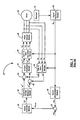
- FIG. 1 shows a typical system 20 that controls speed of an AC motor 22.
- a rotor position sensor such as a resolver 24 or an encoder (not shown), and a signal processing module 26 measure rotor angle ⁇ rm .
- a speed measurement module 28 determines motor speed ⁇ rm from the rotor angle.
- a comparator module 30 determines the difference ⁇ rm_err between the measured speed ⁇ rm and a command speed ⁇ rm *. The difference is fed to a speed controller module 32 that generates a torque command T e * to minimize the difference.
- a torque-to-current mapping module 34 Based on the torque command, a torque-to-current mapping module 34 generates command currents I ds e* and I qs e* .
- a stationary to synchronous phase converter module 36 converts the currents I as , I bs , and I cs to d and q-axis synchronous phase currents I ds e and I qs e .
- a comparator module 38 determines the difference between the currents I ds e* and I ds e .
- Another comparator module 40 determines the difference between the currents I qs e* and I qs e .
- a current controller module 42 Based on the difference in the currents, a current controller module 42 generates synchronous phase command voltages V ds e* and V qs e* .
- a synchronous to stationary phase converter module 44 converts the voltages V ds e* and V qs e* to stationary phase command voltages V a * , V b * , and V c * . Based on the command voltages, an inverter module 46 generates 3-phase voltages that drive the motor at the command speed.
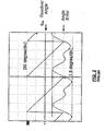
- the motor speed should be accurately measured because errors in measured speed are fed back to the control system and can cause speed fluctuations, system instability, and motor heating. Due to factors such as eccentricity of position sensor, inaccuracy of electrical module, etc., the rotor angle typically has a periodic error, as shown in FIG. 2 . Consequently, the motor speed calculated from the rotor angle has a fluctuating error called ripple, as shown in FIG. 3 .
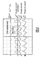
- the ripple is fed back to the speed controller module and distorts the command currents, as shown in FIG. 4 .
- the ripple in command currents distorts the command voltages that drive the motor. As a result, the motor speed fluctuates. Consequently, the motor currents that are measured and fed back to the control system contain ripple, as shown in FIG.
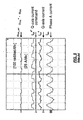
- the ripple is minimized by using a low-pass filter, as shown in FIG. 5 .
- US2005/0067996 A1 describes a motor control apparatus according to the preamble of claim 1 or 5.
- US2003/0025625 A1 describes an analog moving average filter that could be used to conduct ripple filtering.
- the cut-off frequency of the filter cannot be set so low as to completely eliminate the ripple because the low cut-off frequency causes delay in the feedback loop.
- the ripple can also be minimized by lowering the control bandwidth of the speed controller, current control, and a speed observer. This method, however, sacrifices control dynamics and is therefore inadequate for speed control of high-speed motors.
- the present invention provides a system for measuring speed of a high-speed motor.
- a position sensor generates a rotor position signal.
- a signal processing module determines a rotor angle from the rotor position signal.
- a speed observer module calculates a raw speed of the motor.
- a filter module selectively generates a filtered speed of the motor from the raw speed of the motor.
- a frequency-to-period converter module calculates a rotor period from one of the raw speed of the motor and the filtered speed of the motor.
- a divider module calculates number of points in a moving average from the rotor period.
- a moving average filter module adjusts a window size of the moving average to the rotor period.
- a moving average filter removes ripple and harmonics of the ripple from the raw speed of the motor.
- FIG. 1 is a functional block diagram illustrating a typical control system that controls the speed of a motor
- FIG. 2 is a graph illustrating an exemplary error in rotor angle measured using a position sensor
- FIG. 3 is a graph illustrating exemplary ripple component of motor speed calculated from rotor angle
- FIG. 4 is a graph illustrating exemplary current waveforms generated using speed with ripple
- FIG. 5 is a graph illustrating exemplary current waveforms generated using speed information obtained by using a low-pass filter
- FIG. 6 is a functional block diagram illustrating a control system that controls the speed of a high-speed AC motor using the present invention
- FIG. 7 is a functional block diagram illustrating a system for measuring speed of a high-speed AC motor using the present invention
- FIG. 8 is a flowchart illustrating steps performed in a method for measuring speed of a high-speed motor system according to the present invention.
- FIG. 9 is a graph illustrating frequency response of a moving average filter
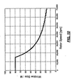
- FIG. 10 is a graph illustrating exemplary relationship between window size of a moving average filter and rotor speed
- FIG. 11A is a graph illustrating exemplary relationship between window size of a moving average filter and ripple at low rotor speed
- FIG. 11B is a graph illustrating exemplary relationship between window size of a moving average filter and ripple at high rotor speed
- FIG. 12 is a graph illustrating exemplary performance of the speed measurement method of the present invention.
- FIG. 13 is a graph illustrating exemplary comparison between frequency responses of a moving average filter and a low-pass filter
- FIG. 14 is a graph illustrating exemplary current waveforms obtained using the speed measurement method of the present invention.
- module, controller and/or device refers to an application specific integrated module (ASIC), an electronic module, a processor (shared, dedicated, or group) and memory that execute one or more software or firmware programs, a combinational logic module, and/or other suitable components that provide the described functionality.
- ASIC application specific integrated module
- processor shared, dedicated, or group
- memory that execute one or more software or firmware programs
- combinational logic module and/or other suitable components that provide the described functionality.
- a motor speed control system 100 includes a motor 22.
- a position sensor such as a resolver 24 or an encoder (not shown), and a signal processing module 26 measure rotor angle ⁇ rm .
- a speed measurement module 110 determines motor speed ⁇ rm from the rotor angle.
- a comparator module 30 determines the difference between the measure speed ⁇ rm and a command speed ⁇ rm * .
- the difference, ⁇ rm_err is fed to a speed controller module 32 that generates a torque command T e * to minimize the speed difference.
- a torque-to-current mapping module 34 Based on the torque command, a torque-to-current mapping module 34 generates d and q-axis command currents I ds e* and I qs e* .
- a stationary to synchronous phase converter module 36 converts the currents I as , I bs , and I cs to d and q-axis synchronous phase currents I ds e and I qs e .
- a comparator module 38 determines the difference between the currents I ds e* and I ds e .
- Another comparator module 40 determines the difference between the currents I qs e* and I qs e .
- a current controller module 42 Based on the difference in the currents, a current controller module 42 generates synchronous phase command voltages V ds e* and V qs e* .
- a synchronous to stationary phase converter module 44 converts the voltages V ds e* and V qs e* to stationary phase command voltages V a * , V b * , and V c * . Based on the command voltages, an inverter module 46 generates 3-phase voltages that drive the motor at the command speed.
- a speed measurement module 110 includes a speed observer 112.
- the speed observer 112 calculates raw speed ⁇ rm_raw of the rotor from rotor angle ⁇ rm . If an encoder (not shown) is used instead of a resolver 24, the raw speed of the rotor can be calculated from the pulse train data using a signal processing module 26.
- the rotor angle has a periodic error due to factors such as eccentricity of sensor, inaccuracy of electrical module etc.
- the raw speed ⁇ rm_raw of the rotor has a fluctuating error called ripple.
- a low-pass filter module 114 reduces the ripple in the raw speed of the rotor and generates a filtered rotor speed ⁇ rm_LPF .
- a divider module 118 calculates the number of points M in a moving average by dividing the period T of the rotor by the sampling time T s .
- a window size of a moving average filter is obtained by multiplying the number of points M in the moving average by a given sampling time T s .
- the window size of a MAF with M points is MT s .
- the window size can be simply represented by M.
- a MAF module 120 adjusts the window size of the MAF to the rotor period T.
- the method 150 begins at step 152 at a sampling time T s .
- rotor angle. ⁇ rm is measured using a resolver 24, or an encoder (not shown), and a signal processing module 26.
- a speed observer module 112 determines raw speed ⁇ rm_raw of the rotor from the rotor angle.
- a low-pass filter 114 removes some of the ripple from the raw speed of the rotor and generates speed ⁇ rm_LPF .
- a frequency to period .converter module 116 divides 2 ⁇ by ⁇ rm_LPF to obtain rotational period T of the rotor.
- a divider module 118 divides the period T by the sampling time T s to obtain number of points M in a moving average.
- a MAF module 120 adjusts the window size of the MAF to the period T of the rotor.
- the MAF module 120 removes the ripple and all harmonics of the ripple from ⁇ rm_LPF and generates motor speed ⁇ rm .
- the speed ⁇ rm is fed back to the speed control system 100, and the method repeats at another sampling time T s .
- the frequency response of a MAF is such that it has infinitive attenuation at frequencies with periods equal to the window size MT s of the filter and its n th harmonics.
- the frequency response of a MAF is zero at frequencies ( ).
- the window size of a MAF is adjusted to the fundamental period of the ripple, the MAF completely removes the ripple and all harmonics of the ripple. Since the fundamental period of the ripple is equal to the period T of the rotor, the window size of the MAF is adjusted to the period T of the rotor to completely remove the ripple and all harmonics of the ripple from the speed of the rotor.
- the window size has upper and lower limits. Consequently, the ripple cannot be completely removed when measuring motor speeds below a certain minimum and above a certain maximum value.
- the window size is inversely proportional to the speed of the rotor. At very low speed, the window size becomes very large, the stop-band frequency of the MAF becomes very low, and the performance of the speed control system degrades. Therefore, the window size has a maximum limit M MAX , and its value determines the lowest rotor speed that can be measured without ripple. Similarly, the window size has a minimum value M MIN , and its value determines the highest rotor speed that can be measured without ripple.
- FIG. 11 A further illustrates an exemplary relationship between window size of a MAF and ripple at low rotor speed.
- FIG. 11B illustrates an exemplary relationship between window size of a MAF and ripple at high rotor speed.
- the window size of the MAF fluctuates due to the ripple present in the raw speed of the rotor. If the window size fluctuates, the ripple in the raw speed of the rotor is reduced but not completely removed. Using a low-pass filter to remove some of the ripple in the raw speed of the rotor reduces the fluctuation in the window size of the MAF. Thus, the MAF attenuates the ripple present in the raw speed of the rotor more effectively when a low-pass filter is used to calculate the window size of the MAF.
- the speed ⁇ rm contains no ripple when the window size of the MAF is adjusted to the period T of the rotor. This is because, as FIG. 13 shows, the attenuation of the MAF is infinite when its window size is adjusted to the period of the rotor.
- the ripple is significantly eliminated from w rm_err when the motor speed ⁇ rm is measured using the MAF with its window size adjusted to the period of the rotor, as shown in FIG. 14 .
- the periodic fluctuations in the command currents and actual motor currents are significantly reduced.
- the residual fluctuation in the motor currents is due to current measurement errors caused by factors such as number of sensors used, leakage inductance of the motor, etc.
- FIG. 14 also shows that the motor current waveform is substantially sinusoidal and contains few harmonics when the MAF used. This low distortion in the motor currents also reduces heating and loss caused by harmonics.
Landscapes
- Physics & Mathematics (AREA)
- General Physics & Mathematics (AREA)
- Engineering & Computer Science (AREA)
- Power Engineering (AREA)
- Control Of Electric Motors In General (AREA)
- Control Of Ac Motors In General (AREA)
- Control Of Motors That Do Not Use Commutators (AREA)
- Control Of Multiple Motors (AREA)
Claims (8)
- Procédé pour mesurer la vitesse d'un moteur à haute vitesse (22), comprenant les étapes consistant à :générer un signal de position de rotor ;déterminer un angle de rotor (θrm) à partir du signal de position de rotor ;calculer une vitesse brute (ωrm_raw) du moteur (22) à partir de l'angle de rotor (θrm) ;caractérisé par les étapes consistant à :générer sélectivement une vitesse filtrée (ωrm_ LPF) du moteur (22) à partir de la vitesse brute (ωrm_raw) du moteur (22) ;calculer une période de rotor (T) à partir de l'une parmi la vitesse brute (ωrm_raw) du moteur (22) et la vitesse filtrée (ωrm_LPF) du moteur (22) ; etcalculer un nombre de points dans une moyenne de mouvement à partir de la période de rotor (T).
- Procédé selon la revendication 1, comprenant en outre l'étape consistant à ajuster une taille de fenêtre de la moyenne de mouvement de la période de rotor (T).
- Procédé selon la revendication 2, comprenant en outre l'étape consistant à supprimer les ondulations et les harmoniques d'ondulations hors de la vitesse brute (ωrm_raw) du moteur (22).
- Procédé selon la revendication 3, comprenant en outre l'étape consistant à supprimer les harmoniques des ondulations hors de la vitesse brute du moteur (22)
- Système pour mesurer la vitesse d'un moteur à haute vitesse (22), comprenant :un capteur de position (24) qui génère un signal de position de rotor ;un module de traitement de signal (26) qui détermine un angle de rotor (θrm) à partir du signal de position de rotor ;un module d'observation de vitesse (112) qui calcule une vitesse brute (ωrm_raw) du moteur (22) à partir de l'angle de rotor (θrm) ;caractérisé parun module de filtre (114) qui génère sélectivement une vitesse filtrée (ωrm_LPF) du moteur (22) à partir de la vitesse brute (ωrm_raw) du moteur (22) ;un module convertisseur fréquence/période (116) qui calcule une période de rotor (T) à partir de l'une parmi la vitesse brute (ωrm_raw) du moteur (22) et la vitesse filtrée (ωrm_LPF) du moteur (22) ; etun module diviseur (118) qui calcule un nombre de points dans une moyenne de mouvement à partir de la période du rotor (T)
- Système selon la revendication 5, comprenant en outre un module de filtre de moyenne de mouvement (120) qui ajuste une taille de fenêtre d'un filtre de moyenne de mouvement à la période du rotor (T).
- Système selon la revendication 6, comprenant en outre un filtre de moyenne de mouvement qui supprime des ondulations hors de la vitesse brute (ωrm_raw) du moteur (22).
- Système selon la revendication 7, dans lequel le filtre de moyenne de mouvement supprime des harmoniques des ondulations hors de la vitesse brute (ωrm_raw) du moteur (22).
Applications Claiming Priority (2)
| Application Number | Priority Date | Filing Date | Title |
|---|---|---|---|
| US11/207,173 US7248989B2 (en) | 2005-08-18 | 2005-08-18 | Speed measurement system for speed control of high-speed motors |
| PCT/US2006/029538 WO2007021505A2 (fr) | 2005-08-18 | 2006-07-31 | Systeme de mesure de la vitesse destine au controle de la vitesse de rotation de moteurs a haute vitesse |
Publications (3)
| Publication Number | Publication Date |
|---|---|
| EP1922549A2 EP1922549A2 (fr) | 2008-05-21 |
| EP1922549A4 EP1922549A4 (fr) | 2011-10-19 |
| EP1922549B1 true EP1922549B1 (fr) | 2012-12-26 |
Family
ID=37758043
Family Applications (1)
| Application Number | Title | Priority Date | Filing Date |
|---|---|---|---|
| EP06788868A Ceased EP1922549B1 (fr) | 2005-08-18 | 2006-07-31 | Systeme de mesure de la vitesse destine au controle de la vitesse de rotation de moteurs a haute vitesse |
Country Status (4)
| Country | Link |
|---|---|
| US (1) | US7248989B2 (fr) |
| EP (1) | EP1922549B1 (fr) |
| CN (1) | CN101292163B (fr) |
| WO (1) | WO2007021505A2 (fr) |
Families Citing this family (16)
| Publication number | Priority date | Publication date | Assignee | Title |
|---|---|---|---|---|
| JP4895703B2 (ja) * | 2006-06-28 | 2012-03-14 | 三洋電機株式会社 | モータ制御装置 |
| US7460974B2 (en) | 2006-07-24 | 2008-12-02 | Delta Electronics, Inc. | Multiple-point smoothing method for motor-speed estimation |
| JP5002335B2 (ja) * | 2007-05-29 | 2012-08-15 | 株式会社東芝 | モータ制御装置,洗濯機及びモータ制御方法 |
| US20090150116A1 (en) * | 2007-12-05 | 2009-06-11 | Ching-Yi Lin | Method for automatically setting initially-estimated rotational frequency in motor frequency measuring system |
| CN102957380B (zh) * | 2011-08-19 | 2014-12-10 | 比亚迪股份有限公司 | 一种电机转速计算方法 |
| US9829502B2 (en) * | 2013-05-30 | 2017-11-28 | Lockheed Martin Corporation | Mechanisms for deriving an accurate timing signal from a noisy waveform |
| JP2017188968A (ja) * | 2014-09-03 | 2017-10-12 | 東芝キヤリア株式会社 | モータ駆動装置 |
| DE102015205772B3 (de) | 2015-03-31 | 2016-04-21 | Schaeffler Technologies AG & Co. KG | Verfahren zur Erzeugung eines Geschwindigkeitssignals eines Elektromotors |
| KR102419489B1 (ko) * | 2015-07-13 | 2022-07-12 | 현대모비스 주식회사 | 모터 속도 측정 장치 및 방법 |
| CN104991082A (zh) * | 2015-07-29 | 2015-10-21 | 湖南工业大学 | 一种基于stc电机转速测量器 |
| JP6654373B2 (ja) * | 2015-08-04 | 2020-02-26 | 青島海爾洗衣机有限公司QingDao Haier Washing Machine Co.,Ltd. | 洗濯機 |
| DE102015222202B3 (de) * | 2015-11-11 | 2016-11-24 | Schaeffler Technologies AG & Co. KG | Verfahren zum Bestimmen eines korrigierten Drehgeschwindigkeitssignals sowie Elektromotoranordnung |
| CN110501516B (zh) * | 2018-05-16 | 2022-02-08 | 中国航天科工飞航技术研究院(中国航天海鹰机电技术研究院) | 用于超高速直线电机的组合测速系统和方法 |
| US11499985B2 (en) | 2019-12-31 | 2022-11-15 | Schneider Electric Systems Usa, Inc. | Low latency variable rotational frequency measurements |
| US12227168B2 (en) * | 2021-03-31 | 2025-02-18 | Sensata Technologies, Inc. | Accurate error estimation in E-motor sensors |
| EP4215878A1 (fr) * | 2022-01-19 | 2023-07-26 | Renesas Electronics America Inc. | Système de capteur de position et procédé de détection d'une erreur d'un système de capteur de position |
Family Cites Families (10)
| Publication number | Priority date | Publication date | Assignee | Title |
|---|---|---|---|---|
| US5377295A (en) * | 1990-11-07 | 1994-12-27 | Matsushita Electric Industrial Co., Ltd. | Speed controller of motor |
| US5642461A (en) * | 1994-11-14 | 1997-06-24 | Seagate Technology, Inc. | Economical wide range speed control system |
| JP3302235B2 (ja) * | 1995-09-29 | 2002-07-15 | 三菱電機株式会社 | 電動機の位置制御装置 |
| JP3944955B2 (ja) * | 1997-07-02 | 2007-07-18 | 株式会社安川電機 | 誘導電動機の誘導起電力推定方法、速度推定方法、軸ずれ補正方法及び誘導電動機制御装置 |
| EP0895344B1 (fr) * | 1997-07-30 | 2003-10-01 | Matsushita Electric Industrial Co., Ltd | Méthode de commande d'ondulation du couple d'un moteur avec aimants permanents à l'intéerieur et régulateur utilisant cette méthode |
| JP3775258B2 (ja) * | 2001-07-31 | 2006-05-17 | 株式会社デンソー | フィルタリング方法及びフィルタ機能を有するa/d変換装置 |
| GB0130150D0 (en) * | 2001-12-18 | 2002-02-06 | Johnson Electric Sa | Method of measuring motor speed |
| JP4301913B2 (ja) * | 2003-09-29 | 2009-07-22 | オークマ株式会社 | モータ制御装置 |
| CN1300590C (zh) * | 2004-05-18 | 2007-02-14 | 桂林星辰电力电子有限公司 | 电机低速运行时使用脉冲编码器的测速方法 |
| CN1286262C (zh) * | 2004-12-31 | 2006-11-22 | 浙江大学 | 电机转速与转子位置的综合测量方法和测量电路 |
-
2005
- 2005-08-18 US US11/207,173 patent/US7248989B2/en not_active Expired - Fee Related
-
2006
- 2006-07-31 EP EP06788868A patent/EP1922549B1/fr not_active Ceased
- 2006-07-31 WO PCT/US2006/029538 patent/WO2007021505A2/fr not_active Ceased
- 2006-07-31 CN CN200680038909XA patent/CN101292163B/zh not_active Expired - Fee Related
Also Published As
| Publication number | Publication date |
|---|---|
| EP1922549A4 (fr) | 2011-10-19 |
| CN101292163A (zh) | 2008-10-22 |
| US20070043528A1 (en) | 2007-02-22 |
| WO2007021505A2 (fr) | 2007-02-22 |
| US7248989B2 (en) | 2007-07-24 |
| EP1922549A2 (fr) | 2008-05-21 |
| CN101292163B (zh) | 2010-10-13 |
| WO2007021505A3 (fr) | 2007-05-03 |
Similar Documents
| Publication | Publication Date | Title |
|---|---|---|
| EP1922549B1 (fr) | Systeme de mesure de la vitesse destine au controle de la vitesse de rotation de moteurs a haute vitesse | |
| US9178454B2 (en) | Apparatus for controlling rotating machine based on output signal of resolver | |
| EP3040690B1 (fr) | Dispositif de correction d'erreur d'angle et procédé de correction d'erreur d'angle pour détecteur de position | |
| JP5173962B2 (ja) | レゾルバ/デジタル変換装置およびレゾルバ/デジタル変換方法 | |
| CN113866480B (zh) | 用于马达控制系统的相电流测量中的偏移误差的检测 | |
| JP6005393B2 (ja) | 車両用レゾルバの異常出力補償方法 | |
| US20040085039A1 (en) | Electric motor control system including position determination and error correction | |
| CN107883990A (zh) | 电动汽车用永磁同步电机旋转变压器零位标定方法及系统 | |
| EP2930843A2 (fr) | Diagnostic de mesure de courant de phase | |
| US8552670B2 (en) | Control circuit of an electric motor with a measure delay compensation and motor system comprising the circuit | |
| EP2869077B1 (fr) | Compensation de décalage pour détection de passage à zéro | |
| EP1772739B1 (fr) | Procédé et appareil de surveillance de l'état d'une machine | |
| US20080021670A1 (en) | Multiple-point smoothing method for motor-speed estimation | |
| JP6305573B2 (ja) | 位置検出器の角度誤差補正装置および角度誤差補正方法 | |
| JP2001197765A (ja) | トルクリップル低減装置 | |
| EP4492673A1 (fr) | Dispositif de commande de moteur et procédé de réglage automatique de celui-ci | |
| JP3729734B2 (ja) | 磁束制御交流システムにおいて磁束中点を補正する方法 | |
| CN115996007A (zh) | 一种电机定子电阻在线辨识的方法、装置及电机 | |
| JP3949134B2 (ja) | ステッピングモータの制御装置 | |
| CN109905064A (zh) | 一种电机电角度确定方法、装置及设备 | |
| KR20180038656A (ko) | 교류전동기의 회전자 위치보정 방법 및 그 장치 | |
| JP3111798B2 (ja) | 可変速駆動装置 | |
| EP4675915A1 (fr) | Procédé et dispositif pour déterminer des excentricités statiques et dynamiques d'un moteur électrique | |
| EP4675914A1 (fr) | Procédé et dispositif pour déterminer des excentricités statiques et dynamiques d'un moteur électrique | |
| US6815921B1 (en) | High performance motor control with feedforward bus supply voltage |
Legal Events
| Date | Code | Title | Description |
|---|---|---|---|
| PUAI | Public reference made under article 153(3) epc to a published international application that has entered the european phase |
Free format text: ORIGINAL CODE: 0009012 |
|
| 17P | Request for examination filed |
Effective date: 20080304 |
|
| AK | Designated contracting states |
Kind code of ref document: A2 Designated state(s): DE |
|
| DAX | Request for extension of the european patent (deleted) | ||
| RBV | Designated contracting states (corrected) |
Designated state(s): DE |
|
| RAP1 | Party data changed (applicant data changed or rights of an application transferred) |
Owner name: GM GLOBAL TECHNOLOGY OPERATIONS LLC |
|
| A4 | Supplementary search report drawn up and despatched |
Effective date: 20110916 |
|
| RIC1 | Information provided on ipc code assigned before grant |
Ipc: G01P 5/00 20060101AFI20110912BHEP Ipc: G06F 15/00 20060101ALI20110912BHEP Ipc: G01P 7/00 20060101ALI20110912BHEP Ipc: G01P 9/00 20060101ALI20110912BHEP |
|
| REG | Reference to a national code |
Ref country code: DE Ref legal event code: R079 Ref document number: 602006033860 Country of ref document: DE Free format text: PREVIOUS MAIN CLASS: G01P0005000000 Ipc: G01P0003480000 |
|
| 17Q | First examination report despatched |
Effective date: 20120608 |
|
| GRAP | Despatch of communication of intention to grant a patent |
Free format text: ORIGINAL CODE: EPIDOSNIGR1 |
|
| RIC1 | Information provided on ipc code assigned before grant |
Ipc: G01P 3/48 20060101AFI20120621BHEP |
|
| GRAS | Grant fee paid |
Free format text: ORIGINAL CODE: EPIDOSNIGR3 |
|
| GRAA | (expected) grant |
Free format text: ORIGINAL CODE: 0009210 |
|
| AK | Designated contracting states |
Kind code of ref document: B1 Designated state(s): DE |
|
| REG | Reference to a national code |
Ref country code: DE Ref legal event code: R096 Ref document number: 602006033860 Country of ref document: DE Effective date: 20130228 |
|
| PLBE | No opposition filed within time limit |
Free format text: ORIGINAL CODE: 0009261 |
|
| STAA | Information on the status of an ep patent application or granted ep patent |
Free format text: STATUS: NO OPPOSITION FILED WITHIN TIME LIMIT |
|
| 26N | No opposition filed |
Effective date: 20130927 |
|
| REG | Reference to a national code |
Ref country code: DE Ref legal event code: R097 Ref document number: 602006033860 Country of ref document: DE Effective date: 20130927 |
|
| PGFP | Annual fee paid to national office [announced via postgrant information from national office to epo] |
Ref country code: DE Payment date: 20180717 Year of fee payment: 13 |
|
| REG | Reference to a national code |
Ref country code: DE Ref legal event code: R119 Ref document number: 602006033860 Country of ref document: DE |
|
| PG25 | Lapsed in a contracting state [announced via postgrant information from national office to epo] |
Ref country code: DE Free format text: LAPSE BECAUSE OF NON-PAYMENT OF DUE FEES Effective date: 20200201 |