EP1923246B1 - Modulierbares Hardtop eines Kraftfahrzeugs - Google Patents
Modulierbares Hardtop eines Kraftfahrzeugs Download PDFInfo
- Publication number
- EP1923246B1 EP1923246B1 EP07301507A EP07301507A EP1923246B1 EP 1923246 B1 EP1923246 B1 EP 1923246B1 EP 07301507 A EP07301507 A EP 07301507A EP 07301507 A EP07301507 A EP 07301507A EP 1923246 B1 EP1923246 B1 EP 1923246B1
- Authority
- EP
- European Patent Office
- Prior art keywords
- roof
- arms
- opening
- rigid panel
- vehicle
- Prior art date
- Legal status (The legal status is an assumption and is not a legal conclusion. Google has not performed a legal analysis and makes no representation as to the accuracy of the status listed.)
- Not-in-force
Links
- 239000011521 glass Substances 0.000 claims abstract description 4
- 239000000463 material Substances 0.000 claims abstract description 4
- 230000002093 peripheral effect Effects 0.000 claims description 9
- 230000003028 elevating effect Effects 0.000 claims 2
- 230000000284 resting effect Effects 0.000 description 2
- 241001244708 Moroccan pepper virus Species 0.000 description 1
- 230000000694 effects Effects 0.000 description 1
- 238000007789 sealing Methods 0.000 description 1
Images


Classifications
-
- B—PERFORMING OPERATIONS; TRANSPORTING
- B60—VEHICLES IN GENERAL
- B60J—WINDOWS, WINDSCREENS, NON-FIXED ROOFS, DOORS, OR SIMILAR DEVICES FOR VEHICLES; REMOVABLE EXTERNAL PROTECTIVE COVERINGS SPECIALLY ADAPTED FOR VEHICLES
- B60J7/00—Non-fixed roofs; Roofs with movable panels, e.g. rotary sunroofs
- B60J7/08—Non-fixed roofs; Roofs with movable panels, e.g. rotary sunroofs of non-sliding type, i.e. movable or removable roofs or panels, e.g. let-down tops or roofs capable of being easily detached or of assuming a collapsed or inoperative position
- B60J7/16—Non-fixed roofs; Roofs with movable panels, e.g. rotary sunroofs of non-sliding type, i.e. movable or removable roofs or panels, e.g. let-down tops or roofs capable of being easily detached or of assuming a collapsed or inoperative position non-foldable and rigid, e.g. a one-piece hard-top or a single rigid roof panel
- B60J7/1628—Non-fixed roofs; Roofs with movable panels, e.g. rotary sunroofs of non-sliding type, i.e. movable or removable roofs or panels, e.g. let-down tops or roofs capable of being easily detached or of assuming a collapsed or inoperative position non-foldable and rigid, e.g. a one-piece hard-top or a single rigid roof panel for covering the passenger compartment
- B60J7/1635—Non-fixed roofs; Roofs with movable panels, e.g. rotary sunroofs of non-sliding type, i.e. movable or removable roofs or panels, e.g. let-down tops or roofs capable of being easily detached or of assuming a collapsed or inoperative position non-foldable and rigid, e.g. a one-piece hard-top or a single rigid roof panel for covering the passenger compartment of non-convertible vehicles
- B60J7/1642—Roof panels, e.g. sunroofs or hatches, movable relative to the main roof structure, e.g. by lifting or pivoting
-
- B—PERFORMING OPERATIONS; TRANSPORTING
- B60—VEHICLES IN GENERAL
- B60J—WINDOWS, WINDSCREENS, NON-FIXED ROOFS, DOORS, OR SIMILAR DEVICES FOR VEHICLES; REMOVABLE EXTERNAL PROTECTIVE COVERINGS SPECIALLY ADAPTED FOR VEHICLES
- B60J7/00—Non-fixed roofs; Roofs with movable panels, e.g. rotary sunroofs
- B60J7/185—Locking arrangements
- B60J7/19—Locking arrangements for rigid panels
Definitions
- the present invention relates to a modular hardtop roof of a motor vehicle.
- the roof clearance of the rear row of seats adjacent to the vehicle trunk is often limited due to style constraints. This case occurs in particular when the vehicle line has a pronounced fall of the flag towards the rear of the vehicle.
- a limited roof clearance can be inconvenient for passengers, for example adults, sitting on the seats in the back row.
- the object of the present invention is to overcome the aforementioned drawbacks and to provide a roof lodge which allows, while maintaining the desired style, to increase the height of the roof when necessary.
- the document DE 3103062 A1 describes a conventional roof pavilion with a single rigid panel.
- the invention relates to a rigid roof of a motor vehicle characterized in that it comprises an opening which can be closed selectively by a rigid panel located in the plane of the roof at its closed position of the opening or by a booster-shaped booster booster overturned open position in the closed position so that its bottom wall projects from a height determined relative to the flag.
- the rigid panel is articulated to the rear transverse edge of the opening and can be moved by tilting about its transverse hinge axis from its closed position of the opening to an unobstructed position. back into the passenger compartment of the vehicle.
- the booster box is mounted articulated by one of its transverse sides to the vehicle at both ends, respectively of two lateral arms, whose opposite ends are mounted hinged to the flag about a transverse axis to the vehicle, located near the transverse edge before the opening, and when the rigid panel occupies its unobstructed position behind the vehicle, the booster box can be folded towards the front of the vehicle, around its joints, to both arm, against the two arms, occupying a suspended position so that the arms rest on the two parallel sides of the booster box perpendicular to the two arms, and the assembly constituted by the two arms, and the booster box can be tilted around the axes of articulation, of the two arms, towards the pavilion so as to introduce the raised booster box through the opening of the Villon.
- the booster casing when tilted to its support position on the arms, is removably attached to these arms by manually releasable locking means.
- the locking means of the booster chamber to the two arms each consist of a hook, secured to the booster chamber opposite its joints to the arms, and a ring secured to the arm, to proximity of its articulation to the flag, the locking hook can be removably attached to the ring.
- the booster box in the closed position is removably attached to the roof by manually unlockable locking means.
- the locking means are constituted by two lateral bolts, integral with the two arms, and which can respectively engage in two transversely fixed strikers spaced from the flag and located near the rear transverse edge of the opening of the pavilion.
- the rigid panel in the closed position is removably attached to the roof by manually unlockable locking means.
- the locking means are constituted by two lateral bolts, integral with the rigid panel and being able to engage respectively in two transverse fixed locks spaced from the roof and located near the transverse edge before the opening flag.
- the roof flag comprises a seal attached to the peripheral edges of the opening of the roof and being adapted to selectively cooperate with the upper face of a peripheral collar of the rigid panel in position. closed or with the upper face of a peripheral collar of the booster box in the closed position.
- the roof flag comprises return springs mounted between the rear transverse edge of the opening of the roof and the edge of the rigid panel which is mounted articulated on the fixed panel and for bringing the rigid panel in its unobstructed position back in the passenger compartment of the vehicle.
- the roof lining comprises two lateral actuators assisting the tilting of the booster box secured to the arms from their suspended position to their raising position through the opening of the roof.
- the rigid panel in the disengaged position, occupies a suspended position inclined towards the rear of the vehicle.
- the booster chamber occupies a position suspended from the arms approximately horizontal.
- the rigid panel comprises a rectangular frame closed by a window.
- the booster box is made at least partially of a transparent rigid material such as glass.
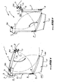
- the Figures 1 to 5 represent a rigid roof lodge 1 intended to cover the passenger compartment of a motor vehicle whose line has a pronounced fall towards the rear window of the vehicle.
- the roof pavilion 1 comprises an opening 2 which can be closed selectively by a rigid panel 3 located in the plane of the roof 1 at its closing position of the opening 2, as visible in the figure 1 , or by a box-shaped booster 4 in the form of open box inverted in the closed position so that its bottom wall 4F protrudes from a height determined relative to the flag 1, as visible in the figure 4 .
- the opening 2 of the roof 1 is located above and opposite the row of rear seats of the vehicle which is not shown in the figures.
- the transverse rear edge 3AR of the rigid panel 3 is articulated on the rear transverse edge 2AR of the opening 2.
- the rigid panel 3 near its rear transverse edge 3AR is connected to the lower wall 1I of the roof 1 near the rear transverse edge 2AR of its opening 2 by two hinges 5 coaxial and transversely spaced to the left and right of the vehicle.
- the rigid panel 3 can swing from its closed position in which its front transverse edge 3AV cooperates with the transverse front edge 2AV of the opening 2 to lock, as represented at figure 1 , to a suspended position inclined towards the rear of the vehicle, as shown in Figures 2 to 4 and 5 .
- each transverse hinge hinge comprises an angled arm 6 pivotable about the transverse hinge axis 7 and which extends forward of the vehicle having its front end secured to the bottom wall 3I of the rigid panel 3 in the vicinity of the rear transverse edge 3AR of this panel.
- the rigid panel 3 In its closed position, the rigid panel 3 is removably attached to its front edge 3AV flag 1 by locking means 8, 9 which are unlockable manually.
- locking means 8, 9 consist of lateral bolts 8, left and right, secured to the rigid panel 3 which can engage respectively latches 9 of the flag 1 so as to lock the rigid panel 3 in the closed position.
- the lateral bolts 8 are located at the lower wall 3I of the rigid panel 3, near its transverse edge before 3AV.
- the strikes 9 are located near the transverse front edge 2AV of the opening 2 of the roof 1 being transversely spaced and facing the bolts 8 of the rigid panel 3 when the latter is in the closed position.
- the roof louver 1 comprises return springs 10, left and right, which are mounted between the flag 1 near the rear transverse edge 2AR of the opening 2 and the rigid panel 3, near its rear transverse edge 3AR, the right return spring not being shown. These springs 10 are transversely spaced and allow to bring the rigid panel 3 to its position released back into the passenger compartment of the vehicle when the locking bolts 8 of the rigid panel 3 are disengaged strikes 9 of the flag 1.
- the roof pavilion 1 comprises two lateral arms 11 transversely spaced, each having an end 12 to the flag 1, near the transverse front edge 2AV of the opening 2 and the other end 13 connected to the booster chamber 4.
- the lateral arms 11 are articulated relative to the roof 1 between a suspended position of the booster chamber 4, as visible on the Figures 1 to 3 and 5 , and a closed position of the opening 2 by the booster chamber 4, as visible on the figure 4 .
- the lateral arms 11 can be moved from their approximately vertical suspended position to their closed position of the opening 2, in the extension of the roof 1.
- each bent arm 15 extends behind the vehicle from its articulated end to the roof 1.
- the lateral arms 11 are mounted hinged relative to the roof 1 by simple hinges 14.
- the booster chamber 4 is hingedly mounted on the ends 13 of the lateral arms 11 between an inactive position in which the booster chamber 4 occupies a position suspended from the arm 11 approximately horizontal, as shown in FIGS. Figures 1 and 2 , and a position in which the booster chamber 4 is folded towards the front of the vehicle against the two arms 11 occupying their suspended position, as shown in FIG. figure 3 .
- the booster casing 4 comprises a flange 17 bordering the opening of the casing 4 and one of the transverse parts of the flange 17 is connected to the two ends 13 of the two lateral arms 11 by means of a hinge. transverse axis to the vehicle. This articulation may consist of two hinges 18 transversely spaced apart from each other.
- locking means 20, 21 which are unlockable manually.
- These locking means 20, 21 are each constituted by a hook 20 integral with the booster chamber 4 opposite its articulation 18 to the arms 11 and a ring 21, secured to the arm 11 near its articulation 14 to the flag 1, which ring 21 may be releasably hooked the corresponding hook 20.
- the assembly constituted by the two arms 11 and the booster chamber 4 can be tilted, around the hinge pin 16 of the two arms 11 to the flag 1, to the flag 1 so as to introduce the booster box 4 upside down through the opening 2 of the flag 1, as visible in the figure 4 .
- the booster chamber 4 in the closed position is removably attached to the roof 1 by locking means 22, 23 which are unlockable manually.
- These locking means 22, 23 are constituted by two lateral bolts 22 which are integral with the lateral arms 11 while being able to slide along these arms and engage respectively in two strikes 23 which are transversely spaced from the flag 1. These strikes 23 are located near the rear transverse edge 2AR of the opening 2 below this edge and are substantially perpendicular to this edge 2AR.
- the roof louver 1 comprises lateral jacks 24, left and right, which are mounted between the roof 1 near the front edge 2AV of the opening 2 and the ends 12 connected to the roof 1 being transversely spaced from one another.
- a seal 25 is fixed on the peripheral edge of the opening 2 of the roof 1.
- This seal 25 has a lower lobe 26 which is intended to cooperate selectively with the upper face of a peripheral flange 27 of the rigid panel 3 in the closed position of this panel or with the upper face of the peripheral collar 17 of the booster box 4 in the closed position of the latter.
- the rigid panel 3 comprises a rectangular frame 30 closed by a window 31 and the booster chamber 4 is made at least partially by a transparent rigid material such as glass.
- the rigid panel 3 can switch to a suspended position, as shown in FIGS. figures 2 and 5 , by pivoting about its transverse hinge axis 7. Due to the effect of the return springs 10, the rigid panel 3 is pushed automatically towards the inside of the vehicle.
- the booster chamber 4 In the position shown in figures 2 and 5 , the booster chamber 4 is always in its inactive position in which it occupies an approximately horizontal suspended position.
- the user rises the assembly formed by the lateral arms 11 secured to the booster chamber 4 to the roof 1 so as to introduce the inverted booster chamber 4 through the opening 2, this tilting being facilitated by the lateral cylinders 24.
- the user pushes the latch bolts 22 of the booster chamber 4 rearwards to engage them in the strikes 23 of the roof 1 and thus, to lock the booster chamber 4 in the closed position of the opening 2.
- the user can reassemble the rigid panel 3 so that it closes the opening 2 of the roof 1 and engage its locking bolts 8 in the latches 9 of the roof 1.
- Such a roof lodge 1 allows, while adapting to the desired style, to increase the roof height 1 of the vehicle when necessary since the bottom wall 4F of the box 4, when it occupies its position of closing the opening 2, protrudes relatively to the roof 1 from a height for receiving the head of a rear passenger in the casing 4.
- roof flag 1 of the invention has means for sealing for the closed positions of the rigid panel 3 and closure of the booster chamber 4.
Landscapes
- Engineering & Computer Science (AREA)
- Mechanical Engineering (AREA)
- Body Structure For Vehicles (AREA)
- Vehicle Interior And Exterior Ornaments, Soundproofing, And Insulation (AREA)
- Insulation, Fastening Of Motor, Generator Windings (AREA)
- Push-Button Switches (AREA)
- Vehicle Step Arrangements And Article Storage (AREA)
Claims (16)
- Starres Verdeck (1) eines Kraftfahrzeugs, dadurch gekennzeichnet, dass es eine Öffnung (2) aufweist, die wahlweise durch eine starre Platte (3), die sich in ihrer Position, in der die Öffnung (2) verschlossen ist, in der Ebene des Verdecks (1) befindet, oder durch einen Verdeckerhöher (4) in Form eines offenen Erhöhungskastens, der in der Position, in der die Öffnung (2) verschlossen ist, umgedreht ist, derart, dass seine Bodenwand (4F) um eine vorgegebene Höhe in Bezug auf die Oberseite des Verdecks (1) vorsteht, verschlossen werden kann.
- Verdeck (1) nach Anspruch 1, dadurch gekennzeichnet, dass die starre Platte (3) an der hinteren Querkante (2AR) der Öffnung (2) angelenkt ist und durch Schwenken um ihre transversale Schwenkachse (7) aus ihrer Position, in der die Öffnung (2) verschlossen ist, in eine nicht befestigte Position hinter dem Fahrgastraum des Fahrzeugs verlagert werden kann.
- Verdeck (1) nach Anspruch 2, dadurch gekennzeichnet, dass der Erhöhungskasten (4) an einer seiner transversalen Seiten (17) am Fahrzeug an zwei Enden (13) von zwei entsprechenden Seitenarmen (11) angelenkt ist, deren gegenüberliegende Enden (12) am Dach (1) schwenkbar um eine transversale Achse des Fahrzeugs (16), die sich in der Nähe der vorderen transversalen Kante (2AV) der Öffnung (2) befindet, angelenkt sind, und dass dann, wenn die starre Platte (3) ihre nicht befestigte Position im hinteren Bereich des Fahrzeugs einnimmt, der Erhöhungskasten (4) zur Vorderseite des Fahrzeugs um seine Gelenke (18) an den zwei Armen (11) gegen die zwei Arme (11), die eine aufgehängte Position einnehmen, umgelegt werden kann, derart, dass sich die Arme (11) auf den zwei parallelen Seiten des Erhöhungskastens (4), die zu den zwei Armen (11) senkrecht sind, abstützen, und dass die Gesamtheit, die durch die zwei Arme (11) und den Erhöhungskasten (4) gebildet ist, um Schwenkachsen (16) der zwei Arme (11) zu dem Verdeck (1) geschwenkt werden kann, derart, dass der umgedrehte Erhöhungskasten (4) durch die Öffnung (2) des Verdecks (1) eingeführt werden kann.
- Verdeck (1) nach Anspruch 3, dadurch gekennzeichnet, dass der Erhöhungskasten (4) bei seiner Schwenkung in die Abstützposition auf den Armen (11) an diesen Armen (11) durch manuell entriegelbare Verriegelungsmittel (20, 21) lösbar befestigt ist.
- Verdeck (1) nach Anspruch 4, dadurch gekennzeichnet, dass die Verriegelungsmittel (20, 21) des Erhöhungskastens (4) an den zwei Armen (11) jeweils durch einen Haken (20), der mit dem Erhöhungskasten (4) gegenüber seinen Gelenken (16) an den Armen (11) fest verbunden ist, und durch einen Ring (21), der mit dem Arm (11) in der Nähe seines Gelenks (4) am Verdeck (1) fest verbunden ist, gebildet sind, wobei der Verriegelungshaken (20) in den Ring (21) lösbar eingehakt werden kann.
- Verdeck (1) nach einem der Ansprüche 3 bis 5, dadurch gekennzeichnet, dass der Erhöhungskasten (4) in der geschlossenen Position am Verdeck (1) durch manuell entriegelbare Verriegelungsmittel (22, 23) lösbar befestigt ist.
- Verdeck (1) nach Anspruch 6, dadurch gekennzeichnet, dass die Verriegelungsmittel (22, 23) durch zwei seitliche Riegel (22) gebildet sind, die mit den zwei Armen (11) fest verbunden sind und in zwei entsprechenden transversal beabstandeten festen Rasten (23) des Verdecks (1), die sich in der Nähe der hinteren transversalen Kante (2AR) der Öffnung (2) des Verdecks (1) befinden, in Eingriff gelangen können.
- Verdeck (1) nach einem der vorhergehenden Ansprüche, dadurch gekennzeichnet, dass die starre Platte (3) in der geschlossenen Position am Verdeck (1) durch manuell entriegelbare Verriegelungsmittel (8, 9) lösbar befestigt ist.
- Verdeck (1) nach Anspruch 8, dadurch gekennzeichnet, dass die Verriegelungsmittel (8, 9) durch zwei seitliche Riegel (8) gebildet sind, die mit der starren Platte (3) fest verbunden sind und in zwei transversal beabstandeten festen Rasten (9) des Verdecks (1), die sich in der Nähe der vorderen transversalen Kante (2AV) der Öffnung (2) des Verdecks (1) befinden, in Eingriff gelangen können.
- Verdeck (1) nach einem der vorhergehenden Ansprüche, dadurch gekennzeichnet, dass es eine an den Umfangskanten der Öffnung (2) des Verdecks (1) befestigte Dichtung (25) aufweist, die dazu bestimmt ist, wahlweise mit der oberen Fläche eines Umfangskranzes (27) der starren Platte (3) in der geschlossenen Position oder mit der oberen Fläche eines Umfangskranzes (17) des Erhöhungskastens (4) in der geschlossenen Position zusammenzuwirken.
- Verdeck (1) nach einem der Ansprüche 2 bis 10, dadurch gekennzeichnet, dass es Rückstellfedern (10) aufweist, die zwischen der hinteren transversalen Kante (2AR) der Öffnung (2) des Verdecks (1) und der Kante der starren Platte (3), die an der festen Platte angelenkt ist, montiert sind und ermöglichen, die starre Platte (3) in ihre nicht befestigte Position im hinteren Bereich des Fahrgastraums des Fahrzeugs zu bringen.
- Verdeck (1) nach einem der Ansprüche 3 bis 11, dadurch gekennzeichnet, dass es zwei seitliche Stellzylinder für die Unterstützung der Schwenkung (24) des mit den Armen (11) fest verbundenen Erhöhungskastens (4) aus ihrer aufgehängten Position in ihre Erhöhungsposition durch die Öffnung (2) des Verdecks (1) enthält.
- Verdeck (1) nach einem der Ansprüche 2 bis 12, dadurch gekennzeichnet, dass die starre Platte (3) in der nicht befestigten Position eine zur Rückseite des Fahrzeugs geneigte aufgehängte Position einnimmt.
- Verdeck (1) nach einem der Ansprüche 3 bis 11, dadurch gekennzeichnet, dass der Erhöhungskasten (4) in der inaktiven Position eine angenähert horizontale, an den Armen (11) aufgehängte Position einnimmt.
- Verdeck (1) nach einem der vorhergehenden Ansprüche, dadurch gekennzeichnet, dass die starre Platte (3) einen durch eine Glasscheibe (31) geschlossenen rechtwinkligen Rahmen (30) enthält.
- Verdeck (1) nach einem der vorhergehenden Ansprüche, dadurch gekennzeichnet, dass der Erhöhungskasten (4) wenigstens teilweise aus einem lichtdurchlässigen starren Material wie etwa Glas verwirklicht ist.
Applications Claiming Priority (1)
| Application Number | Priority Date | Filing Date | Title |
|---|---|---|---|
| FR0654949A FR2908694B1 (fr) | 2006-11-16 | 2006-11-16 | Pavillon de toit rigide modulable d'un vehicule automobile. |
Publications (2)
| Publication Number | Publication Date |
|---|---|
| EP1923246A1 EP1923246A1 (de) | 2008-05-21 |
| EP1923246B1 true EP1923246B1 (de) | 2010-05-26 |
Family
ID=38123745
Family Applications (1)
| Application Number | Title | Priority Date | Filing Date |
|---|---|---|---|
| EP07301507A Not-in-force EP1923246B1 (de) | 2006-11-16 | 2007-10-29 | Modulierbares Hardtop eines Kraftfahrzeugs |
Country Status (5)
| Country | Link |
|---|---|
| EP (1) | EP1923246B1 (de) |
| AT (1) | ATE468994T1 (de) |
| DE (1) | DE602007006740D1 (de) |
| ES (1) | ES2346360T3 (de) |
| FR (1) | FR2908694B1 (de) |
Family Cites Families (4)
| Publication number | Priority date | Publication date | Assignee | Title |
|---|---|---|---|---|
| AU4039872A (en) * | 1972-03-24 | 1973-09-27 | Westfalia-Werke Franz Knobel & Sohne Kg | Camping van with cutaway roof |
| DE3103062C2 (de) * | 1981-01-30 | 1984-08-30 | Daimler-Benz Ag, 7000 Stuttgart | Kraftfahrzeugdach |
| JP2000052777A (ja) * | 1998-08-12 | 2000-02-22 | Anetsukusu:Kk | 油圧により高さを変更できる車載用収納庫 |
| DE20305022U1 (de) * | 2003-03-28 | 2003-05-28 | WESTFALIA Van Conversion GmbH, 33378 Rheda-Wiedenbrück | Aufstelldach mit flexibler Seitenwand für Wohnmobile oder -anhänger |
-
2006
- 2006-11-16 FR FR0654949A patent/FR2908694B1/fr not_active Expired - Fee Related
-
2007
- 2007-10-29 ES ES07301507T patent/ES2346360T3/es active Active
- 2007-10-29 DE DE602007006740T patent/DE602007006740D1/de active Active
- 2007-10-29 EP EP07301507A patent/EP1923246B1/de not_active Not-in-force
- 2007-10-29 AT AT07301507T patent/ATE468994T1/de not_active IP Right Cessation
Also Published As
| Publication number | Publication date |
|---|---|
| EP1923246A1 (de) | 2008-05-21 |
| ATE468994T1 (de) | 2010-06-15 |
| DE602007006740D1 (de) | 2010-07-08 |
| ES2346360T3 (es) | 2010-10-14 |
| FR2908694B1 (fr) | 2009-02-13 |
| FR2908694A1 (fr) | 2008-05-23 |
Similar Documents
| Publication | Publication Date | Title |
|---|---|---|
| FR2752777A1 (fr) | Capote pliante pour vehicules | |
| EP1412213B1 (de) | Kabriolett mit versenkbarem dach | |
| EP1234702B1 (de) | Kombi-Kraftfahrzeug mit einem variablen Dach/Heckbereich | |
| EP1923246B1 (de) | Modulierbares Hardtop eines Kraftfahrzeugs | |
| EP2106967A1 (de) | Kippmulde für die Rückgewinnung von Betonabfällen | |
| EP1234758B1 (de) | Personenkraftwagen , umwandelbar von einem Kombi in einem Pickup | |
| EP1234756B1 (de) | Kraftfahrzeug vom Kombi-umwandelbarem Typ | |
| EP3888979B1 (de) | Versenkbarer fahrradträger | |
| EP1234757B1 (de) | Personenkraftwagen , umwandelbar von einem Kombi in einem Pickup | |
| EP1234755B1 (de) | Umwandelbarer Personenkraftwagen | |
| FR2851510A1 (fr) | Dispositif de toit escamotable et vehicule equipe d'un tel dispositif | |
| FR2878473A1 (fr) | Pavillon escamotable de vehicule | |
| EP1806255B1 (de) | Befestigungseinheit eines Kofferraumdeckels für ein Kraftfahrzeug, und Kraftfahrzeug mit solch einer Befestigungseinheit | |
| EP1712390B1 (de) | Faltdach für ein KFZ und dazugehöriges KFZ | |
| FR2845053A1 (fr) | Vehicule automobile du type comportant un volet arriere articule a sa base sur la structure du vehicule | |
| FR2865163A1 (fr) | Vehicule a toit decouvrable et hayon arriere | |
| WO1989002375A1 (fr) | Vehicule de plein air a dossiers de sieges rabattables | |
| EP1690714B1 (de) | Cabriolet-Fahrzeug | |
| EP1690715A1 (de) | Cabriolet-Fahrzeug, welches als Pick-Up konfiguriert werden kann | |
| FR2892665A1 (fr) | Vehicule automobile equipe d'un toit escamotable, d'un hayon et d'une traverse de protection des passagers porte par ledit hayon | |
| FR2970687A1 (fr) | Dispositif de rangement escamotable pour element de toit amovible d'un vehicule dans le coffre du vehicule. | |
| EP1588896A1 (de) | Hintere Abdeckung für ein Kraftfahrzeug | |
| EP0112733A1 (de) | Kabine für Schwerlastenfahrzeug | |
| FR2885326A1 (fr) | Vehicule du type cabriolet a toit rigide avec cloison fixe | |
| FR2851506A1 (fr) | Dispositif de porte de coffre et vehicule equipe d'un tel dispositif |
Legal Events
| Date | Code | Title | Description |
|---|---|---|---|
| PUAI | Public reference made under article 153(3) epc to a published international application that has entered the european phase |
Free format text: ORIGINAL CODE: 0009012 |
|
| AK | Designated contracting states |
Kind code of ref document: A1 Designated state(s): AT BE BG CH CY CZ DE DK EE ES FI FR GB GR HU IE IS IT LI LT LU LV MC MT NL PL PT RO SE SI SK TR |
|
| AX | Request for extension of the european patent |
Extension state: AL BA HR MK RS |
|
| 17P | Request for examination filed |
Effective date: 20080918 |
|
| AKX | Designation fees paid |
Designated state(s): AT BE BG CH CY CZ DE DK EE ES FI FR GB GR HU IE IS IT LI LT LU LV MC MT NL PL PT RO SE SI SK TR |
|
| GRAP | Despatch of communication of intention to grant a patent |
Free format text: ORIGINAL CODE: EPIDOSNIGR1 |
|
| GRAS | Grant fee paid |
Free format text: ORIGINAL CODE: EPIDOSNIGR3 |
|
| GRAA | (expected) grant |
Free format text: ORIGINAL CODE: 0009210 |
|
| AK | Designated contracting states |
Kind code of ref document: B1 Designated state(s): AT BE BG CH CY CZ DE DK EE ES FI FR GB GR HU IE IS IT LI LT LU LV MC MT NL PL PT RO SE SI SK TR |
|
| REG | Reference to a national code |
Ref country code: GB Ref legal event code: FG4D Free format text: NOT ENGLISH |
|
| REG | Reference to a national code |
Ref country code: CH Ref legal event code: EP |
|
| REG | Reference to a national code |
Ref country code: IE Ref legal event code: FG4D Free format text: LANGUAGE OF EP DOCUMENT: FRENCH |
|
| REF | Corresponds to: |
Ref document number: 602007006740 Country of ref document: DE Date of ref document: 20100708 Kind code of ref document: P |
|
| REG | Reference to a national code |
Ref country code: NL Ref legal event code: VDEP Effective date: 20100526 |
|
| REG | Reference to a national code |
Ref country code: ES Ref legal event code: FG2A Ref document number: 2346360 Country of ref document: ES Kind code of ref document: T3 |
|
| LTIE | Lt: invalidation of european patent or patent extension |
Effective date: 20100526 |
|
| REG | Reference to a national code |
Ref country code: GB Ref legal event code: 746 Effective date: 20101006 |
|
| PG25 | Lapsed in a contracting state [announced via postgrant information from national office to epo] |
Ref country code: LT Free format text: LAPSE BECAUSE OF FAILURE TO SUBMIT A TRANSLATION OF THE DESCRIPTION OR TO PAY THE FEE WITHIN THE PRESCRIBED TIME-LIMIT Effective date: 20100526 Ref country code: SE Free format text: LAPSE BECAUSE OF FAILURE TO SUBMIT A TRANSLATION OF THE DESCRIPTION OR TO PAY THE FEE WITHIN THE PRESCRIBED TIME-LIMIT Effective date: 20100526 |
|
| PG25 | Lapsed in a contracting state [announced via postgrant information from national office to epo] |
Ref country code: AT Free format text: LAPSE BECAUSE OF FAILURE TO SUBMIT A TRANSLATION OF THE DESCRIPTION OR TO PAY THE FEE WITHIN THE PRESCRIBED TIME-LIMIT Effective date: 20100526 Ref country code: FI Free format text: LAPSE BECAUSE OF FAILURE TO SUBMIT A TRANSLATION OF THE DESCRIPTION OR TO PAY THE FEE WITHIN THE PRESCRIBED TIME-LIMIT Effective date: 20100526 Ref country code: SI Free format text: LAPSE BECAUSE OF FAILURE TO SUBMIT A TRANSLATION OF THE DESCRIPTION OR TO PAY THE FEE WITHIN THE PRESCRIBED TIME-LIMIT Effective date: 20100526 Ref country code: LV Free format text: LAPSE BECAUSE OF FAILURE TO SUBMIT A TRANSLATION OF THE DESCRIPTION OR TO PAY THE FEE WITHIN THE PRESCRIBED TIME-LIMIT Effective date: 20100526 Ref country code: IS Free format text: LAPSE BECAUSE OF FAILURE TO SUBMIT A TRANSLATION OF THE DESCRIPTION OR TO PAY THE FEE WITHIN THE PRESCRIBED TIME-LIMIT Effective date: 20100926 |
|
| PG25 | Lapsed in a contracting state [announced via postgrant information from national office to epo] |
Ref country code: PL Free format text: LAPSE BECAUSE OF FAILURE TO SUBMIT A TRANSLATION OF THE DESCRIPTION OR TO PAY THE FEE WITHIN THE PRESCRIBED TIME-LIMIT Effective date: 20100526 Ref country code: CY Free format text: LAPSE BECAUSE OF FAILURE TO SUBMIT A TRANSLATION OF THE DESCRIPTION OR TO PAY THE FEE WITHIN THE PRESCRIBED TIME-LIMIT Effective date: 20100526 |
|
| REG | Reference to a national code |
Ref country code: IE Ref legal event code: FD4D |
|
| PG25 | Lapsed in a contracting state [announced via postgrant information from national office to epo] |
Ref country code: PT Free format text: LAPSE BECAUSE OF FAILURE TO SUBMIT A TRANSLATION OF THE DESCRIPTION OR TO PAY THE FEE WITHIN THE PRESCRIBED TIME-LIMIT Effective date: 20100927 Ref country code: NL Free format text: LAPSE BECAUSE OF FAILURE TO SUBMIT A TRANSLATION OF THE DESCRIPTION OR TO PAY THE FEE WITHIN THE PRESCRIBED TIME-LIMIT Effective date: 20100526 Ref country code: IE Free format text: LAPSE BECAUSE OF FAILURE TO SUBMIT A TRANSLATION OF THE DESCRIPTION OR TO PAY THE FEE WITHIN THE PRESCRIBED TIME-LIMIT Effective date: 20100526 Ref country code: EE Free format text: LAPSE BECAUSE OF FAILURE TO SUBMIT A TRANSLATION OF THE DESCRIPTION OR TO PAY THE FEE WITHIN THE PRESCRIBED TIME-LIMIT Effective date: 20100526 Ref country code: DK Free format text: LAPSE BECAUSE OF FAILURE TO SUBMIT A TRANSLATION OF THE DESCRIPTION OR TO PAY THE FEE WITHIN THE PRESCRIBED TIME-LIMIT Effective date: 20100526 |
|
| PG25 | Lapsed in a contracting state [announced via postgrant information from national office to epo] |
Ref country code: RO Free format text: LAPSE BECAUSE OF FAILURE TO SUBMIT A TRANSLATION OF THE DESCRIPTION OR TO PAY THE FEE WITHIN THE PRESCRIBED TIME-LIMIT Effective date: 20100526 Ref country code: SK Free format text: LAPSE BECAUSE OF FAILURE TO SUBMIT A TRANSLATION OF THE DESCRIPTION OR TO PAY THE FEE WITHIN THE PRESCRIBED TIME-LIMIT Effective date: 20100526 Ref country code: CZ Free format text: LAPSE BECAUSE OF FAILURE TO SUBMIT A TRANSLATION OF THE DESCRIPTION OR TO PAY THE FEE WITHIN THE PRESCRIBED TIME-LIMIT Effective date: 20100526 |
|
| REG | Reference to a national code |
Ref country code: ES Ref legal event code: GC2A Effective date: 20110316 |
|
| PLBE | No opposition filed within time limit |
Free format text: ORIGINAL CODE: 0009261 |
|
| STAA | Information on the status of an ep patent application or granted ep patent |
Free format text: STATUS: NO OPPOSITION FILED WITHIN TIME LIMIT |
|
| PG25 | Lapsed in a contracting state [announced via postgrant information from national office to epo] |
Ref country code: GR Free format text: LAPSE BECAUSE OF FAILURE TO SUBMIT A TRANSLATION OF THE DESCRIPTION OR TO PAY THE FEE WITHIN THE PRESCRIBED TIME-LIMIT Effective date: 20100827 |
|
| BERE | Be: lapsed |
Owner name: PEUGEOT CITROEN AUTOMOBILES S.A. Effective date: 20101031 |
|
| 26N | No opposition filed |
Effective date: 20110301 |
|
| PG25 | Lapsed in a contracting state [announced via postgrant information from national office to epo] |
Ref country code: MC Free format text: LAPSE BECAUSE OF NON-PAYMENT OF DUE FEES Effective date: 20101031 |
|
| REG | Reference to a national code |
Ref country code: DE Ref legal event code: R097 Ref document number: 602007006740 Country of ref document: DE Effective date: 20110228 |
|
| PG25 | Lapsed in a contracting state [announced via postgrant information from national office to epo] |
Ref country code: BE Free format text: LAPSE BECAUSE OF NON-PAYMENT OF DUE FEES Effective date: 20101031 |
|
| PG25 | Lapsed in a contracting state [announced via postgrant information from national office to epo] |
Ref country code: MT Free format text: LAPSE BECAUSE OF FAILURE TO SUBMIT A TRANSLATION OF THE DESCRIPTION OR TO PAY THE FEE WITHIN THE PRESCRIBED TIME-LIMIT Effective date: 20100526 |
|
| REG | Reference to a national code |
Ref country code: CH Ref legal event code: PL |
|
| PG25 | Lapsed in a contracting state [announced via postgrant information from national office to epo] |
Ref country code: CH Free format text: LAPSE BECAUSE OF NON-PAYMENT OF DUE FEES Effective date: 20111031 Ref country code: LI Free format text: LAPSE BECAUSE OF NON-PAYMENT OF DUE FEES Effective date: 20111031 |
|
| PG25 | Lapsed in a contracting state [announced via postgrant information from national office to epo] |
Ref country code: HU Free format text: LAPSE BECAUSE OF FAILURE TO SUBMIT A TRANSLATION OF THE DESCRIPTION OR TO PAY THE FEE WITHIN THE PRESCRIBED TIME-LIMIT Effective date: 20101127 Ref country code: BG Free format text: LAPSE BECAUSE OF FAILURE TO SUBMIT A TRANSLATION OF THE DESCRIPTION OR TO PAY THE FEE WITHIN THE PRESCRIBED TIME-LIMIT Effective date: 20100526 Ref country code: LU Free format text: LAPSE BECAUSE OF NON-PAYMENT OF DUE FEES Effective date: 20101029 |
|
| PG25 | Lapsed in a contracting state [announced via postgrant information from national office to epo] |
Ref country code: TR Free format text: LAPSE BECAUSE OF FAILURE TO SUBMIT A TRANSLATION OF THE DESCRIPTION OR TO PAY THE FEE WITHIN THE PRESCRIBED TIME-LIMIT Effective date: 20100526 |
|
| PGFP | Annual fee paid to national office [announced via postgrant information from national office to epo] |
Ref country code: GB Payment date: 20120924 Year of fee payment: 6 |
|
| PGFP | Annual fee paid to national office [announced via postgrant information from national office to epo] |
Ref country code: IT Payment date: 20120921 Year of fee payment: 6 |
|
| PGFP | Annual fee paid to national office [announced via postgrant information from national office to epo] |
Ref country code: DE Payment date: 20120924 Year of fee payment: 6 |
|
| PGFP | Annual fee paid to national office [announced via postgrant information from national office to epo] |
Ref country code: ES Payment date: 20120920 Year of fee payment: 6 |
|
| PG25 | Lapsed in a contracting state [announced via postgrant information from national office to epo] |
Ref country code: BG Free format text: LAPSE BECAUSE OF FAILURE TO SUBMIT A TRANSLATION OF THE DESCRIPTION OR TO PAY THE FEE WITHIN THE PRESCRIBED TIME-LIMIT Effective date: 20100826 |
|
| PGFP | Annual fee paid to national office [announced via postgrant information from national office to epo] |
Ref country code: FR Payment date: 20131028 Year of fee payment: 7 |
|
| GBPC | Gb: european patent ceased through non-payment of renewal fee |
Effective date: 20131029 |
|
| REG | Reference to a national code |
Ref country code: DE Ref legal event code: R119 Ref document number: 602007006740 Country of ref document: DE Effective date: 20140501 |
|
| PG25 | Lapsed in a contracting state [announced via postgrant information from national office to epo] |
Ref country code: GB Free format text: LAPSE BECAUSE OF NON-PAYMENT OF DUE FEES Effective date: 20131029 |
|
| PG25 | Lapsed in a contracting state [announced via postgrant information from national office to epo] |
Ref country code: IT Free format text: LAPSE BECAUSE OF NON-PAYMENT OF DUE FEES Effective date: 20131029 Ref country code: DE Free format text: LAPSE BECAUSE OF NON-PAYMENT OF DUE FEES Effective date: 20140501 |
|
| REG | Reference to a national code |
Ref country code: ES Ref legal event code: FD2A Effective date: 20150708 |
|
| PG25 | Lapsed in a contracting state [announced via postgrant information from national office to epo] |
Ref country code: ES Free format text: LAPSE BECAUSE OF NON-PAYMENT OF DUE FEES Effective date: 20131030 |
|
| REG | Reference to a national code |
Ref country code: FR Ref legal event code: ST Effective date: 20150630 |
|
| PG25 | Lapsed in a contracting state [announced via postgrant information from national office to epo] |
Ref country code: FR Free format text: LAPSE BECAUSE OF NON-PAYMENT OF DUE FEES Effective date: 20141031 |