EP1923264A2 - Aussenleuchte für Kraftfahrzeuge - Google Patents
Aussenleuchte für Kraftfahrzeuge Download PDFInfo
- Publication number
- EP1923264A2 EP1923264A2 EP07380312A EP07380312A EP1923264A2 EP 1923264 A2 EP1923264 A2 EP 1923264A2 EP 07380312 A EP07380312 A EP 07380312A EP 07380312 A EP07380312 A EP 07380312A EP 1923264 A2 EP1923264 A2 EP 1923264A2
- Authority
- EP
- European Patent Office
- Prior art keywords
- lens
- casing
- tongue
- flange
- wall
- Prior art date
- Legal status (The legal status is an assumption and is not a legal conclusion. Google has not performed a legal analysis and makes no representation as to the accuracy of the status listed.)
- Withdrawn
Links
- 230000008878 coupling Effects 0.000 claims abstract description 13
- 238000010168 coupling process Methods 0.000 claims abstract description 13
- 238000005859 coupling reaction Methods 0.000 claims abstract description 13
- 230000036961 partial effect Effects 0.000 claims abstract description 9
- 230000000717 retained effect Effects 0.000 claims description 2
- 238000005452 bending Methods 0.000 description 2
- 230000037431 insertion Effects 0.000 description 2
- 238000003780 insertion Methods 0.000 description 2
- 230000000284 resting effect Effects 0.000 description 2
- 230000006978 adaptation Effects 0.000 description 1
- 230000000694 effects Effects 0.000 description 1
- 238000009434 installation Methods 0.000 description 1
- 230000000670 limiting effect Effects 0.000 description 1
- 230000002829 reductive effect Effects 0.000 description 1
Images





Classifications
-
- B—PERFORMING OPERATIONS; TRANSPORTING
- B60—VEHICLES IN GENERAL
- B60Q—ARRANGEMENT OF SIGNALLING OR LIGHTING DEVICES, THE MOUNTING OR SUPPORTING THEREOF OR CIRCUITS THEREFOR, FOR VEHICLES IN GENERAL
- B60Q1/00—Arrangement of optical signalling or lighting devices, the mounting or supporting thereof or circuits therefor
- B60Q1/26—Arrangement of optical signalling or lighting devices, the mounting or supporting thereof or circuits therefor the devices being primarily intended to indicate the vehicle, or parts thereof, or to give signals, to other traffic
- B60Q1/30—Arrangement of optical signalling or lighting devices, the mounting or supporting thereof or circuits therefor the devices being primarily intended to indicate the vehicle, or parts thereof, or to give signals, to other traffic for indicating rear of vehicle, e.g. by means of reflecting surfaces
- B60Q1/302—Arrangement of optical signalling or lighting devices, the mounting or supporting thereof or circuits therefor the devices being primarily intended to indicate the vehicle, or parts thereof, or to give signals, to other traffic for indicating rear of vehicle, e.g. by means of reflecting surfaces mounted in the vicinity, e.g. in the middle, of a rear window
-
- B—PERFORMING OPERATIONS; TRANSPORTING
- B60—VEHICLES IN GENERAL
- B60Q—ARRANGEMENT OF SIGNALLING OR LIGHTING DEVICES, THE MOUNTING OR SUPPORTING THEREOF OR CIRCUITS THEREFOR, FOR VEHICLES IN GENERAL
- B60Q1/00—Arrangement of optical signalling or lighting devices, the mounting or supporting thereof or circuits therefor
- B60Q1/26—Arrangement of optical signalling or lighting devices, the mounting or supporting thereof or circuits therefor the devices being primarily intended to indicate the vehicle, or parts thereof, or to give signals, to other traffic
- B60Q1/2619—Arrangement of optical signalling or lighting devices, the mounting or supporting thereof or circuits therefor the devices being primarily intended to indicate the vehicle, or parts thereof, or to give signals, to other traffic built in the vehicle body
- B60Q1/2623—Details of the fastening means
- B60Q1/263—Snap-in fasteners
-
- B—PERFORMING OPERATIONS; TRANSPORTING
- B60—VEHICLES IN GENERAL
- B60Q—ARRANGEMENT OF SIGNALLING OR LIGHTING DEVICES, THE MOUNTING OR SUPPORTING THEREOF OR CIRCUITS THEREFOR, FOR VEHICLES IN GENERAL
- B60Q1/00—Arrangement of optical signalling or lighting devices, the mounting or supporting thereof or circuits therefor
- B60Q1/26—Arrangement of optical signalling or lighting devices, the mounting or supporting thereof or circuits therefor the devices being primarily intended to indicate the vehicle, or parts thereof, or to give signals, to other traffic
- B60Q1/2619—Arrangement of optical signalling or lighting devices, the mounting or supporting thereof or circuits therefor the devices being primarily intended to indicate the vehicle, or parts thereof, or to give signals, to other traffic built in the vehicle body
- B60Q1/2653—Arrangement of optical signalling or lighting devices, the mounting or supporting thereof or circuits therefor the devices being primarily intended to indicate the vehicle, or parts thereof, or to give signals, to other traffic built in the vehicle body with arrangement for sealing the device with respect to the vehicle body, or for concealing gaps between the device and the vehicle body
Definitions
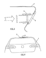
- the luminous indicator of the invention is intended to be assembled in an opening of the bodywork panel made for example in the panel of the rear hatch of a vehicle, and it is of the type formed by a casing, by way of a box open at one of its bases and located inside the bodywork panel or hatch, and by a lens fixed to the casing, closing its open base and the opening of the bodywork.
- a connecting strip is arranged in the casing which supports the visible light source through the lens.
- the indicator of the invention can be assembled on areas of the bodywork that do not require a minimum inclination, and the assembly position corresponds with the final position of the indicator.
- the wall of the casing extends axially, in the upper part of the indicator, into at least one tongue that can bend transversely, on which tongue portions of the wall of the lens are internally abutted.
- the mentioned tongue has a flange aimed towards the wall of the lens, as well as a window located outside the mentioned flange, close to the free edge thereof.
- a gasket is arranged between the edge of the opening of the bodywork panel and the lens, which gasket is retained by the edge of the tongue of the wall of the casing in the maximum coupling position between lens and casing.
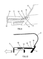
- the indicator shown in the disassembled position, is formed by a casing 3, by way of a box, closed at one of its bases 4 and open at the opposite base, which is closed by a lens 5. Assembled inside the casing 4 there is a connecting strip 6 supporting the light source that will be visible through the lens 5.
- the lens has in the wall portion 9 opposite to the tongue 8 of the casing, two windows 12 and 13 having dimensions that are greater than the flange 10 of the tongue and which are axially separated from one another.
- This lens further has a flange 14, aimed towards the tongue 8, which is located outside the two windows 12 and 13 and which has smaller dimensions than the window 11 of the tongue 8, as can be seen in Figure 12 .
- a gasket 16 is inserted to assure the closure between the lens 8 and the edge of the opening of the panel 1, which gasket, as seen in Figures 8 and 9 , will be compressed between the edge of the opening of the panel 1 and the lens 5.
- Figures 13 to 15 show successive positions between the lens 5 and the casing 3, showing the disassembly of the luminous indicator from outside from the position of Figures 8 and 9 , in which the flange 10 is inserted in the first window 12 of the lens 5, such that the tongue 8 is bent outwardly due to the effect of the flange 14 of the wall of the lens, providing the fastening of the assembly.
- a change in the fixing occurs by stretching the lens 5 from outside, the flange 10 going from the first groove 12 to the second groove 13.
- a small force is then exerted towards the inside of the hatch, as shown in Figure 11 , such that the flange 14 of the wall of the lens 5 is opposite to the window 11 of the tongue 8, as shown in Figure 12 .
- the assembly can be carried out from outside by means of a single operation, whereby attaining considerable time savings in the assembly line.
- the disassembly can be carried out from outside in three operations and from inside in just two operations, always by means of applying force either towards the inside or towards the outside of the hatch, thus obtaining the change in the fixing of the flange 10 of the panel 1 in one of the windows 12 or 13 of the lens 5.
- the assembly of the indicator of the invention furthermore does not require the area of the bodywork in which it is assembled to have a minimum inclination since it does not require a turn of the indicator once it is introduced.
Landscapes
- Engineering & Computer Science (AREA)
- Mechanical Engineering (AREA)
- Lighting Device Outwards From Vehicle And Optical Signal (AREA)
- Non-Portable Lighting Devices Or Systems Thereof (AREA)
Applications Claiming Priority (1)
| Application Number | Priority Date | Filing Date | Title |
|---|---|---|---|
| ES200602480U ES1064323Y (es) | 2006-11-16 | 2006-11-16 | Indicador luminoso exterior para vehiculos automoviles |
Publications (2)
| Publication Number | Publication Date |
|---|---|
| EP1923264A2 true EP1923264A2 (de) | 2008-05-21 |
| EP1923264A3 EP1923264A3 (de) | 2009-06-03 |
Family
ID=38293607
Family Applications (1)
| Application Number | Title | Priority Date | Filing Date |
|---|---|---|---|
| EP07380312A Withdrawn EP1923264A3 (de) | 2006-11-16 | 2007-11-12 | Aussenleuchte für Kraftfahrzeuge |
Country Status (2)
| Country | Link |
|---|---|
| EP (1) | EP1923264A3 (de) |
| ES (1) | ES1064323Y (de) |
Cited By (2)
| Publication number | Priority date | Publication date | Assignee | Title |
|---|---|---|---|---|
| ITTO20100082A1 (it) * | 2010-02-05 | 2011-08-06 | Olsa Spa | Luce di veicolo con sistema di bloccaggio a molle. |
| EP2542448B1 (de) * | 2010-03-05 | 2017-09-20 | Bayerische Motoren Werke Aktiengesellschaft | Fahrzeugleuchte und verfahren zum montieren einer fahrzeugleuchte |
Family Cites Families (5)
| Publication number | Priority date | Publication date | Assignee | Title |
|---|---|---|---|---|
| US5319530A (en) * | 1992-05-01 | 1994-06-07 | Public Safety Equipment, Inc. | Hood for a unidirectional lamp |
| DE29911621U1 (de) * | 1999-07-03 | 1999-09-23 | Sidler GmbH & Co, 72072 Tübingen | Befestigungsvorrichtung für ein Leuchtengehäuse |
| FR2833660B1 (fr) * | 2001-12-17 | 2004-08-13 | Sli Miniature Lighting Sa | Agrafe de fixation d'une piece sur une carrosserie automobile |
| ES1055604Y (es) * | 2003-09-24 | 2004-04-16 | Seat Sa | Indicador luminoso exterior para tercera luz de freno de vehiculos automoviles. |
| DE202005006376U1 (de) * | 2005-04-21 | 2005-06-16 | Fer Fahrzeugelektrik Gmbh | Fahrzeugleuchte mit einem im Einbauzustand lösbaren Bauteil |
-
2006
- 2006-11-16 ES ES200602480U patent/ES1064323Y/es not_active Expired - Fee Related
-
2007
- 2007-11-12 EP EP07380312A patent/EP1923264A3/de not_active Withdrawn
Non-Patent Citations (1)
| Title |
|---|
| None |
Cited By (2)
| Publication number | Priority date | Publication date | Assignee | Title |
|---|---|---|---|---|
| ITTO20100082A1 (it) * | 2010-02-05 | 2011-08-06 | Olsa Spa | Luce di veicolo con sistema di bloccaggio a molle. |
| EP2542448B1 (de) * | 2010-03-05 | 2017-09-20 | Bayerische Motoren Werke Aktiengesellschaft | Fahrzeugleuchte und verfahren zum montieren einer fahrzeugleuchte |
Also Published As
| Publication number | Publication date |
|---|---|
| ES1064323U (es) | 2007-03-01 |
| EP1923264A3 (de) | 2009-06-03 |
| ES1064323Y (es) | 2007-06-01 |
Similar Documents
| Publication | Publication Date | Title |
|---|---|---|
| US8585121B2 (en) | Device for fastening a vehicle interior trim panel | |
| US5857731A (en) | Vehicle door with a triangular mirror bracket for mounting an outside mirror | |
| EP1502824A1 (de) | Befestigung für den Haltegurt eines vorhangförmigen Seitenairbags | |
| WO2008051903A3 (en) | Flush mounted plastic window for vehicles | |
| EP1785302A2 (de) | Türstruktur eines Kraftfahrzeuges | |
| EP1923264A2 (de) | Aussenleuchte für Kraftfahrzeuge | |
| JP5108431B2 (ja) | 自動車用バイザー | |
| US20100059973A1 (en) | Air Bag Device | |
| JPH11321319A (ja) | 自動車車体用の車体部分 | |
| US20180208037A1 (en) | Mounting structure for doorframe molding | |
| US20120079694A1 (en) | Installation frame for accommodating a device in an installation opening | |
| JP2009029295A (ja) | 自動車用内装部品の取付構造 | |
| JP3112152B2 (ja) | カバー体の取付構造 | |
| JP4372647B2 (ja) | リヤカメラの取付け構造 | |
| EP1925489B1 (de) | Instrumententafel für ein Kraftfahrzeug | |
| CN116985725A (zh) | 可维护部件的嵌套式两步卡扣连接 | |
| JP2001239823A (ja) | 車両用アウトレットバルブ装置 | |
| JP4303459B2 (ja) | 照明ランプ | |
| JP2005335427A (ja) | ベンチレータの取り付け構造 | |
| JP2005186903A (ja) | カバー | |
| JP4229360B2 (ja) | 車両用ドアハンドルの取付構造 | |
| KR100553095B1 (ko) | 자동차의 도어 아웃사이드 벨트 웨더 스트립의 끝부분고정구조 | |
| JP2000009287A (ja) | キャップ | |
| JP2007531656A (ja) | ウインドウワイパ装置 | |
| JP2024041383A (ja) | 車両構造 |
Legal Events
| Date | Code | Title | Description |
|---|---|---|---|
| PUAI | Public reference made under article 153(3) epc to a published international application that has entered the european phase |
Free format text: ORIGINAL CODE: 0009012 |
|
| AK | Designated contracting states |
Kind code of ref document: A2 Designated state(s): AT BE BG CH CY CZ DE DK EE ES FI FR GB GR HU IE IS IT LI LT LU LV MC MT NL PL PT RO SE SI SK TR |
|
| AX | Request for extension of the european patent |
Extension state: AL BA HR MK RS |
|
| PUAL | Search report despatched |
Free format text: ORIGINAL CODE: 0009013 |
|
| AK | Designated contracting states |
Kind code of ref document: A3 Designated state(s): AT BE BG CH CY CZ DE DK EE ES FI FR GB GR HU IE IS IT LI LT LU LV MC MT NL PL PT RO SE SI SK TR |
|
| AX | Request for extension of the european patent |
Extension state: AL BA HR MK RS |
|
| 17P | Request for examination filed |
Effective date: 20091120 |
|
| 17Q | First examination report despatched |
Effective date: 20091216 |
|
| AKX | Designation fees paid |
Designated state(s): DE ES FR GB IT |
|
| RBV | Designated contracting states (corrected) |
Designated state(s): DE ES FR GB IT |
|
| STAA | Information on the status of an ep patent application or granted ep patent |
Free format text: STATUS: THE APPLICATION IS DEEMED TO BE WITHDRAWN |
|
| 18D | Application deemed to be withdrawn |
Effective date: 20111101 |