EP1923612A2 - Absperrhahn - Google Patents
Absperrhahn Download PDFInfo
- Publication number
- EP1923612A2 EP1923612A2 EP08151265A EP08151265A EP1923612A2 EP 1923612 A2 EP1923612 A2 EP 1923612A2 EP 08151265 A EP08151265 A EP 08151265A EP 08151265 A EP08151265 A EP 08151265A EP 1923612 A2 EP1923612 A2 EP 1923612A2
- Authority
- EP
- European Patent Office
- Prior art keywords
- valve
- water
- seat
- stopcock
- plug
- Prior art date
- Legal status (The legal status is an assumption and is not a legal conclusion. Google has not performed a legal analysis and makes no representation as to the accuracy of the status listed.)
- Withdrawn
Links
Images




Classifications
-
- F—MECHANICAL ENGINEERING; LIGHTING; HEATING; WEAPONS; BLASTING
- F16—ENGINEERING ELEMENTS AND UNITS; GENERAL MEASURES FOR PRODUCING AND MAINTAINING EFFECTIVE FUNCTIONING OF MACHINES OR INSTALLATIONS; THERMAL INSULATION IN GENERAL
- F16K—VALVES; TAPS; COCKS; ACTUATING-FLOATS; DEVICES FOR VENTING OR AERATING
- F16K11/00—Multiple-way valves, e.g. mixing valves; Pipe fittings incorporating such valves
- F16K11/10—Multiple-way valves, e.g. mixing valves; Pipe fittings incorporating such valves with two or more closure members not moving as a unit
- F16K11/20—Multiple-way valves, e.g. mixing valves; Pipe fittings incorporating such valves with two or more closure members not moving as a unit operated by separate actuating members
- F16K11/22—Multiple-way valves, e.g. mixing valves; Pipe fittings incorporating such valves with two or more closure members not moving as a unit operated by separate actuating members with an actuating member for each valve, e.g. interconnected to form multiple-way valves
-
- F—MECHANICAL ENGINEERING; LIGHTING; HEATING; WEAPONS; BLASTING
- F16—ENGINEERING ELEMENTS AND UNITS; GENERAL MEASURES FOR PRODUCING AND MAINTAINING EFFECTIVE FUNCTIONING OF MACHINES OR INSTALLATIONS; THERMAL INSULATION IN GENERAL
- F16K—VALVES; TAPS; COCKS; ACTUATING-FLOATS; DEVICES FOR VENTING OR AERATING
- F16K31/00—Actuating devices; Operating means; Releasing devices
- F16K31/002—Actuating devices; Operating means; Releasing devices actuated by temperature variation
-
- F—MECHANICAL ENGINEERING; LIGHTING; HEATING; WEAPONS; BLASTING
- F24—HEATING; RANGES; VENTILATING
- F24H—FLUID HEATERS, e.g. WATER OR AIR HEATERS, HAVING HEAT-GENERATING MEANS, e.g. HEAT PUMPS, IN GENERAL
- F24H9/00—Details
- F24H9/12—Arrangements for connecting heaters to circulation pipes
- F24H9/13—Arrangements for connecting heaters to circulation pipes for water heaters
- F24H9/133—Storage heaters
- F24H9/136—Arrangement of inlet valves used therewith
-
- G—PHYSICS
- G05—CONTROLLING; REGULATING
- G05D—SYSTEMS FOR CONTROLLING OR REGULATING NON-ELECTRIC VARIABLES
- G05D23/00—Control of temperature
- G05D23/01—Control of temperature without auxiliary power
- G05D23/13—Control of temperature without auxiliary power by varying the mixing ratio of two fluids having different temperatures
- G05D23/1306—Control of temperature without auxiliary power by varying the mixing ratio of two fluids having different temperatures for liquids
- G05D23/132—Control of temperature without auxiliary power by varying the mixing ratio of two fluids having different temperatures for liquids with temperature sensing element
- G05D23/134—Control of temperature without auxiliary power by varying the mixing ratio of two fluids having different temperatures for liquids with temperature sensing element measuring the temperature of mixed fluid
- G05D23/1346—Control of temperature without auxiliary power by varying the mixing ratio of two fluids having different temperatures for liquids with temperature sensing element measuring the temperature of mixed fluid with manual temperature setting means
Definitions
- the present invention relates to a stopcock for a water heater.
- Combination valves in which there is a mixing of cold water into the hot water from the water heater to avoid scalding are already known.
- these combination valves have a number of drawbacks such as inadequate leakproofing and inadequate inspection possibilities for detecting leakage points in the valves, and that the associated piping must be dismantled for replacement of the combination valve's check valve with suitable parts.
- Additional drawbacks include problems of furring in the valves and variable hot water draw-off temperature when cold water is drawn at the same time.
- the combination valve as disclosed herein seeks to solve the aforementioned problems associated with the prior art, and to provide a solution having a minimum number of parts and a simple structure, which permits rational production at reduced productions costs.
- a first aspect relates to a combination valve for a water heater, comprising an inlet for cold water, an outlet for cold water to the water heater, an inlet for hot water from the water heater, and an outlet for hot water from the combination valve.
- the valve further comprises a check valve having a check valve piston and a mixing valve equipped with a temperature sensor that expands in its longitudinal direction with increased water temperature.
- the temperature sensor has a head at one end and an end journal at its opposite, other end.
- the combination valve is characterised in that a seat/shaft element includes a first fixed seat for the end journal of the temperature sensor and a second seat from which the temperature sensor head is lifted when the hot water through the inlet from the water heater is at a cut-in temperature or higher.
- a part of the temperature sensor extends through an opening in the seat/shaft element around which opening the seat is provided, and which seat/shaft element further comprises a shaft for sliding movement of the check valve's check valve piston.
- the opening and a plurality of openings in proximity to the shaft provide fluid communication between the check valve and the mixing valve when the head of the temperature sensor is lifted from the seat, so that cold water is mixed with the hot water from the inlet.
- Another aspect relates to an annular gasket for a check valve intended for a water heater, which check valve includes a valve piston for sealing against a flat seat.
- the gasket is characterised in that an annular portion of the gasket comprising a surface for sealing against the seat is essentially in the form of a semi O-ring gasket.
- the present invention relates to a stopcock for a water heater, which stopcock comprises an end plug with an opening through which there extends a spindle in threaded engagement with the opening.
- the stopcock is characterised in that a conical surface of the spindle is in sealing abutment with a correspondingly shaped seat in the end plug when the stopcock is in an open position.
- a final aspect relates to a plug for a valve intended for a water heater.
- the end plug is made having threads for threaded engagement with corresponding threads in the valve body, and is characterised in that a round surface of the plug is in sealing abutment with a conical seat in the valve body when the plug is fully screwed into the body.
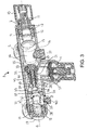
- a first embodiment of a combination valve or fitting 1 having a substantially tubular body, preferably of brass, along a centre axis S.
- a stopcock 2 is provided, and arranged at the opposite, second end along the centre axis S of the combination valve 1 is a combined check and mixing valve 3.
- an overflow or relief valve 4 is arranged about halfway between the stopcock 2 and the check and mixing valve 3 along the centre axis S, and at right angles thereto, is arranged an overflow or relief valve 4 with an overflow 9, which overflow or relief valve 4 is known per se .
- the detailed structure and function of the last-mentioned will therefore only be described insofar as it is of consequence for the invention.
- the stopcock 2 comprises a stop wheel 10 secured to a spindle 11.
- the spindle 11 has external threads, and is passed through a centric and internally threaded opening in an end plug 12.
- the end plug 12 is further made having external threads in threaded engagement with internal threads formed on a tubular outer part of the combination valve 1 body.
- the spindle 11 is further provided with an outer piston 15 which, when the stopcock 2 is moved into a closed position by turning the stop wheel 10, rests sealingly against a seat 16 with a centric opening and formed peripherally in the body.
- the piston 15 is advantageously formed as an integral part of the spindle 11, and the whole spindle 11 and the end plug 12 are preferably made of plastic. By using plastic furring problems are avoided, and at the same time the seal between the conical surface 14 and the seat in the end plug 12 is enhanced because of the inherent "failure" of plastic.
- the combined check and mixing valve 3 is made having an externally threaded end plug 17 in threaded engagement with internal threads formed on a tubular opposite outer part of the combination valve 1 body.
- a centric bore 18 in the end plug 17 serves as a first seat for a coil spring 19, whilst a first flange surface 20 of a temperature sensor 21 serves as a second seat for the coil spring 19.
- An opposite, second flange surface 22 of the temperature sensor 21 is in abutment with a peripherally formed end surface 23 of a seat/shaft element 24.
- An opposite, second peripherally formed surface 25 of the seat/shaft element 24 rests against a peripherally formed seat 26 located in the body and having a centric opening 39 through which a part of the temperature sensor 21 extends.
- the seat/shaft element 24 is further made having a plurality of spaced supporting ribs 29 which together hold a centrically arranged shaft 27, so that between the supporting ribs 29 there are openings 48 for water flow.
- a calibration hole 28 is centrically arranged in the transition between the supporting ribs 29 and the shaft 27, which calibration hole 28 serves as a second seat for the temperature sensor 21, and where the cut-in temperature for the mixing of cold water into the hot water from the water heater is determined by the depth of the calibration hole 28, as will be described in more detail below.
- a check valve piston 30 is slidably secured to the shaft 27, the valve piston 30 being provided with a centric blind hole 49 which receives the shaft 27.
- a coil spring 31 Arranged on the outside of the check valve piston 30, essentially parallel to the longitudinal axis S, is a coil spring 31, which at one end thereof bears against a seat 50 adjacent to the supporting ribs 29, and at the other end thereof bears against a peripheral flange surface 32 of the check valve 30.
- An opposite peripheral surface 33 of the check valve piston 30 constitutes a sealing surface which the coil spring 31, under given operating conditions, biases into sealing abutment with a peripherally arranged seat 35 in the essentially tubular body of the combination valve 1, as will be explained in more detail below.
- the seat 35 and the seat 16 define between them a flow passage 36, and an inspection plug 37 in threaded cooperation with an opening into the flow passage 36 is provided through the combination valve 1 body. Removal of the inspection plug thus allows inspection of the seal between the check valve piston 30 and its seat 35, and the seal between the stopcock 2 piston 15 and seat 16, as will be explained in more detail below.
- the function of the combination valve 1 is as follows: Cold water from the water mains is in fluid communication with the interior of the combination valve 1 through the inlet 5, and the water pressure in the flow passage 36 is the same as in the water mains.
- the coil spring 31 of the check valve has such spring stiffness that the check valve piston 30 seals against the seat 35, apart from when hot water is drawn off via the outlet 7 so that the pressure on an inner side 45 of the check valve piston 30 drops. This prevents water from the water heater from flowing into the flow passage 36 and being mixed with water from the mains.
- the temperature sensor 21 is so provided that it expands in its longitudinal direction, essentially parallel to the longitudinal direction S, as a function of the temperature to which the head 38 of the temperature sensor is subjected. More specifically, the head 38 of the temperature sensor is filled with a wax which expands under conditions of rising temperature, and presses the end journal 46 of the temperature sensor 21 out.
- the flange surface 22 of the temperature sensor 21 When the cut-in temperature is reached, the flange surface 22 of the temperature sensor 21 will be lifted from abutment with the peripherally formed end surface 23 of the seat/shaft element 24, and the cut-in temperature will increase with the depth of the calibration hole 28, the bottom of the calibration hole 28 constituting a fixed seat for the temperature sensor 21.
- the coil spring 19 acts on the temperature sensor 21 in a direction opposite to the expansion direction, and has a spring stiffness that contracts the temperature sensor so that the flange surface 22 of the temperature sensor 21 is brought into sealing abutment with the end surface 23 of the seat/shaft element 24 when the temperature of the water from the inlet 6 falls below the cut-in or calibration temperature again.
- the centric bore 18 which serves as a seat for the coil spring 19 is also carefully bored so that the coil spring 19 is supported along a part of its length and that the flange surface 22 is thus brought into true abutment with the end surface 23 of the seat/shaft element 24.
- the combination valve 1 will thus have a factory-set fixed, precalibrated temperature setting which cannot be changed by the user.
- the head 38 of the temperature sensor 21 will be lifted from its abutment with the end surface 23 so that cold water flows through the openings between the supporting ribs 29 of the seat/shaft element 24, though the opening 39 through which a part of the temperature sensor 21 extends in order ultimately to be mixed with the water from the water heater so that the water from the outlet 7 maintains the calibration temperature.
- the opening 39 will be kept closed by the temperature sensor 21 head 38.
- the opening 39 will thus constitute the partition between the hot water zone and the cold water zone of the combination valve 1, respectively to the left and to the right in the figures.
- the centric opening 39 through which a part of the temperature sensor 21 extends, is advantageously such that the temperature of the water from the outlet 7 does not fall below a predetermined value, for example, 50°C, when the water heater is at normal temperature.
- a predetermined value for example, 50°C
- a correspondingly threaded breather plug 40 for use when emptying the water heater of water. Emptying is carried out by first closing the stopcock 2 and then removing breather plug 40, whereupon the pressure in the water heater is adjusted to counteract vacuum. Upon subsequent unscrewing of the relief valve 4 handwheel, water from the water heater will be emptied through the overflow 9.
- servicing of the check and mixing valve 3 can be carried out simply by dismantling the combination valve 1, i.e., without dismantling the associated piping. This is done by first closing the stopcock 2 and then unscrewing the end plug 17. Subsequently, all the parts of the check and mixing valve 3 can be removed from the body of the combination valve 1 through the opening for the end plug 17.
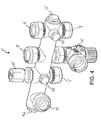
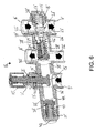
- FIG. 4-6 there is shown a second embodiment of the combination valve or fitting 1', which mainly differs from the first embodiment in that in addition to a hot water outlet 7' there is also provided a cold water outlet 41 with check valve.
- the parts that are the same as or similar to those in the first embodiment are designated by the same reference numerals, but with the suffix of an apostrophe ('), and reference is made primarily to the description above for the function and structure of these parts.
- the overflow or relief valve 4' is known per se, and constitutes a separate thread-fastened part that has been omitted from Figures 5 and 6 , and where the outlet of the overflow valve is indicated by the reference numeral 4'.
- the check valve piston 30' in a closed position, rests sealingly against a seat 44, and only opens when cold water in drawn off via the outlet 41. It is thus impossible for cold water from taps in the dwelling to be passed back to the water mains and the water heater via the valve 1' inlet 5'.
- One advantage of the integral cold water solution in the combination valve 1' compared with the combination valve 1 is that since all water from the dwelling's main intake is passed via the valve 1', a sudden temperature increase in the hot draw-off water from 7' on the simultaneous drawing of large amounts of cold water, for example when a washing machine starts drawing water, is avoided. This is because the pressure loss is almost the same on the cold water and the hot water side of the valve 1' (respectively on the left-hand side and the right-hand side of the figures).
- Removal of an inspection plug 37' allows for inspection of the seal between the check piston 30' and its seat 44, between the check piston 30' and its seats 35' and between the stopcock piston 15' and its seat 16'. Removal of the inspection plug 37' is carried out after the stopcock 2' has been closed, and if the sealing is correct, water will not leak through the opening of the inspection plug 37' after the plug has been removed and a first volume of water under pressure, "trapped" between the aforementioned pistons, has possibly run out. If water continues to leak out through the inspection plug 37' opening, this indicates leakage between one or more of the aforementioned pistons and seats.
- check valve pistons can then be changed one after the other until the leakage has been eliminated, and as was the case for the first embodiment, this can be done without dismantling the associated piping by unscrewing the end plugs 17' and 42'.
- a pressure gauge for leakage testing of the valve 1' and for testing the water pressure may also be connected to the inspection plug 37' opening.
- plugs 12, 17, 37, 12', 17', 37', 42 are made having a round, annular surface 55, 55' in sealing abutment with a conical seat in the valve 1,1' body when the plug has been screwed in fully.
- the use of O-rings, thread sealing tape and the like will thus be unnecessary in order to obtain satisfactory sealing between respective plug 12, 17, 37, 12', 17', 37', 42 and the body.
- the plug 12, 17, 37, 12', 17', 37', 42 is preferably made of plastic and the valve 1; 1' body is preferably made of metal, preferably brass, so that the plastic will be deformed slightly when the plug 12, 17, 37, 12', 17', 37', 42 is screwed in fully.
- a common feature of all valves in the field is that the stopcock is typically closed only a few times in the course of the valve's lifetime, and normally is in an open position.
- the check valve or valves of the valve will be opened and closed each time water is drawn, and thus typically many hundred thousand times during the valve's lifetime.
- the last-mentioned is therefore subjected to decidedly the most wear, and will be the part or parts that must usually be replaced.
- the wear is however reduced to a minimum, in that the surface 33, 33' consists of the surface of an annular gasket, preferably of rubber, which is essentially made in the form of a semi O-ring gasket, and which seals against a flat seat. Tests have shown that this solution seals at a pressure of as little as 200 mmVS between the gasket and the seat.
- the annular gasket advantageously has a rectangular part with an inner radial portion that fits in said rectangular groove 53 and an outer radial portion with which the part having the form of an essentially semi O-ring gasket is integrally made.
- FIGS 7a and 7b are two perspective views of the seat/shaft element 24, 24' which is a component of the combination valve 1, 1'described above.
- This element is preferably made of plastic to prevent furring, and the same applies also to the valve pistons 30, 30', 43, 15, 15' and the end plugs 17, 17' and 42.
Landscapes
- Engineering & Computer Science (AREA)
- General Engineering & Computer Science (AREA)
- Mechanical Engineering (AREA)
- Physics & Mathematics (AREA)
- Automation & Control Theory (AREA)
- Combustion & Propulsion (AREA)
- Chemical & Material Sciences (AREA)
- General Physics & Mathematics (AREA)
- Thermal Sciences (AREA)
- Check Valves (AREA)
- Multiple-Way Valves (AREA)
- Temperature-Responsive Valves (AREA)
- Pens And Brushes (AREA)
- Pipe Accessories (AREA)
- Domestic Plumbing Installations (AREA)
- Compressor (AREA)
- Valve-Gear Or Valve Arrangements (AREA)
- Cookers (AREA)
- Water Treatment By Sorption (AREA)
Applications Claiming Priority (2)
| Application Number | Priority Date | Filing Date | Title |
|---|---|---|---|
| NO20040650A NO324909B1 (no) | 2004-02-13 | 2004-02-13 | Kombinasjonsventil for varmtvannsbereder |
| EP05710942A EP1723370B1 (de) | 2004-02-13 | 2005-02-09 | Kombinationsventil |
Related Parent Applications (1)
| Application Number | Title | Priority Date | Filing Date |
|---|---|---|---|
| EP05710942A Division EP1723370B1 (de) | 2004-02-13 | 2005-02-09 | Kombinationsventil |
Publications (2)
| Publication Number | Publication Date |
|---|---|
| EP1923612A2 true EP1923612A2 (de) | 2008-05-21 |
| EP1923612A3 EP1923612A3 (de) | 2014-09-03 |
Family
ID=34793423
Family Applications (2)
| Application Number | Title | Priority Date | Filing Date |
|---|---|---|---|
| EP05710942A Expired - Lifetime EP1723370B1 (de) | 2004-02-13 | 2005-02-09 | Kombinationsventil |
| EP08151265.9A Withdrawn EP1923612A3 (de) | 2004-02-13 | 2005-02-09 | Absperrhahn |
Family Applications Before (1)
| Application Number | Title | Priority Date | Filing Date |
|---|---|---|---|
| EP05710942A Expired - Lifetime EP1723370B1 (de) | 2004-02-13 | 2005-02-09 | Kombinationsventil |
Country Status (5)
| Country | Link |
|---|---|
| EP (2) | EP1723370B1 (de) |
| AT (1) | ATE393366T1 (de) |
| DE (1) | DE602005006246T2 (de) |
| NO (1) | NO324909B1 (de) |
| WO (1) | WO2005078359A1 (de) |
Cited By (1)
| Publication number | Priority date | Publication date | Assignee | Title |
|---|---|---|---|---|
| JP2014077516A (ja) * | 2012-10-11 | 2014-05-01 | Fuji Koki Corp | 複連式混合弁装置 |
Families Citing this family (12)
| Publication number | Priority date | Publication date | Assignee | Title |
|---|---|---|---|---|
| GB2451362B (en) * | 2005-05-13 | 2009-03-18 | Alpha Therm Ltd | Heating system valve arrangement |
| GB0526331D0 (en) | 2005-12-23 | 2006-02-01 | Horne Engineering Co Ltd | Mixer tap |
| WO2007114704A1 (en) * | 2006-04-06 | 2007-10-11 | Braathen Thor F | Valve arrangement |
| NO324135B1 (no) * | 2006-04-06 | 2007-09-03 | Tor Frolich Braathen | Trykkreduksjonsventil |
| ES2322315B1 (es) * | 2007-06-18 | 2010-03-17 | Orkli, S. Coop | Grupo de seguridad para calentadores electricos de agua. |
| DE202010011996U1 (de) | 2010-08-31 | 2010-11-11 | Zehnder Verkaufs- Und Verwaltungs Ag | Verschlussstopfen |
| NO334053B1 (no) * | 2011-03-24 | 2013-11-25 | Braathen Thor F | Forbedret kombinasjonsventil |
| JP6498434B2 (ja) * | 2014-12-22 | 2019-04-10 | 柳生ゴム化成株式会社 | モジュール方式集合弁 |
| CN105782510A (zh) * | 2016-05-06 | 2016-07-20 | 厦门建霖工业有限公司 | 恒温分水阀芯、恒温分水龙头及其工作方法 |
| CN109723105B (zh) * | 2018-12-14 | 2020-11-06 | 浙江一佳厨卫科技股份有限公司 | 一种具有节水功能的淋浴装置 |
| NO345644B1 (no) * | 2019-11-14 | 2021-05-25 | Braathen Thor F | Ventiler for vannvarmere med 1 eller 2 stusser og oppvarming fra ekstern varme kilde |
| CN111156332B (zh) | 2020-01-16 | 2025-02-14 | 惠达卫浴股份有限公司 | 一种自动控制水路流量模块 |
Family Cites Families (5)
| Publication number | Priority date | Publication date | Assignee | Title |
|---|---|---|---|---|
| FR1482169A (fr) * | 1966-04-06 | 1967-05-26 | Term | Perfectionnements aux vannes à double réglage pour chauffage central et applications analogues |
| NO157153C (no) * | 1985-10-08 | 1988-01-27 | Braathen Thor F | Anordning ved armatur med termostatstyrt blandeventil for varmtvannsbeholder av trykkberedertypen. |
| NO162982C (no) * | 1987-10-29 | 1990-03-14 | Braathen Thor F | Anordning ved armatur med kombinert avstengningsventil ogtilbakeslagsventil for varmtvannsbeholder av trykkberedertypen. |
| JPH04501162A (ja) * | 1988-10-11 | 1992-02-27 | ブラーテン,トール,フロリッヒ | コンプレッサー型の熱水加熱器のための組合わされた遮断弁と逆止め弁とを有する据付品装置 |
| NO305968B1 (no) * | 1997-08-13 | 1999-08-23 | Braathen Thor F | Anordning ved armaturhus for vannvarmer |
-
2004
- 2004-02-13 NO NO20040650A patent/NO324909B1/no unknown
-
2005
- 2005-02-09 EP EP05710942A patent/EP1723370B1/de not_active Expired - Lifetime
- 2005-02-09 DE DE602005006246T patent/DE602005006246T2/de not_active Expired - Lifetime
- 2005-02-09 EP EP08151265.9A patent/EP1923612A3/de not_active Withdrawn
- 2005-02-09 AT AT05710942T patent/ATE393366T1/de not_active IP Right Cessation
- 2005-02-09 WO PCT/NO2005/000046 patent/WO2005078359A1/en not_active Ceased
Cited By (1)
| Publication number | Priority date | Publication date | Assignee | Title |
|---|---|---|---|---|
| JP2014077516A (ja) * | 2012-10-11 | 2014-05-01 | Fuji Koki Corp | 複連式混合弁装置 |
Also Published As
| Publication number | Publication date |
|---|---|
| EP1723370A1 (de) | 2006-11-22 |
| WO2005078359A1 (en) | 2005-08-25 |
| DE602005006246T2 (de) | 2009-06-25 |
| EP1723370B1 (de) | 2008-04-23 |
| DE602005006246D1 (de) | 2008-06-05 |
| EP1923612A3 (de) | 2014-09-03 |
| NO20040650L (no) | 2004-11-15 |
| ATE393366T1 (de) | 2008-05-15 |
| NO324909B1 (no) | 2008-01-02 |
Similar Documents
| Publication | Publication Date | Title |
|---|---|---|
| KR101061486B1 (ko) | 유체작동밸브 | |
| EP1723370B1 (de) | Kombinationsventil | |
| RU2500956C2 (ru) | Клапан с функцией δр (перепада давления) и функцией ограничения потока | |
| US6315210B1 (en) | Thermostatic mixing valve | |
| JP4246564B2 (ja) | 管内減圧調整装置 | |
| US20020017327A1 (en) | Single seat valve apparatus | |
| US10487482B2 (en) | Adjustable temperature regulated faucet | |
| US8627846B2 (en) | Pressure regulator having an integral pilot and self-relieving mechanism | |
| EP1807659A1 (de) | Vorrichtung zum regeln eines mediumflusses in einem heiz- und kühlsystem | |
| US11739509B2 (en) | Adjustable temperature regulated faucet | |
| ZA200605480B (en) | System disconnector | |
| JP3752586B2 (ja) | 流体制御器 | |
| JP2018105382A (ja) | 通水器具及び給湯装置 | |
| KR200464589Y1 (ko) | 볼 타입 앵글밸브 일체형 감압밸브 | |
| CN101512164A (zh) | 用于液压元件的操控系统 | |
| US4276899A (en) | Faucets | |
| FI66066C (fi) | Tryckreduceringsventil | |
| JP4330519B2 (ja) | 減圧弁 | |
| NO324912B1 (no) | Plugg for ventil for varmtvannsbereder | |
| NO324913B1 (no) | Stoppekran for varmtvannsbereder | |
| US611781A (en) | Island | |
| KR200295869Y1 (ko) | 감압 밸브 | |
| EP1258570A2 (de) | Doppelfunktionzuführvorrichting für Toilettenspülkästen | |
| US1196879A (en) | Faucet. | |
| AU2011250096B2 (en) | Thermostatic valve with improved pressure balancing |
Legal Events
| Date | Code | Title | Description |
|---|---|---|---|
| PUAI | Public reference made under article 153(3) epc to a published international application that has entered the european phase |
Free format text: ORIGINAL CODE: 0009012 |
|
| AC | Divisional application: reference to earlier application |
Ref document number: 1723370 Country of ref document: EP Kind code of ref document: P |
|
| AK | Designated contracting states |
Kind code of ref document: A2 Designated state(s): AT BE BG CH CY CZ DE DK EE ES FI FR GB GR HU IE IS IT LI LT LU MC NL PL PT RO SE SI SK TR |
|
| PUAL | Search report despatched |
Free format text: ORIGINAL CODE: 0009013 |
|
| AK | Designated contracting states |
Kind code of ref document: A3 Designated state(s): AT BE BG CH CY CZ DE DK EE ES FI FR GB GR HU IE IS IT LI LT LU MC NL PL PT RO SE SI SK TR |
|
| RIC1 | Information provided on ipc code assigned before grant |
Ipc: F24H 9/12 20060101ALI20140725BHEP Ipc: F16K 1/52 20060101ALI20140725BHEP Ipc: F16K 31/00 20060101ALI20140725BHEP Ipc: G05D 23/13 20060101ALI20140725BHEP Ipc: F16K 11/22 20060101AFI20140725BHEP |
|
| AKX | Designation fees paid |
Designated state(s): AT BE BG CH CY CZ DE DK EE ES FI FR GB GR HU IE IS IT LI LT LU MC NL PL PT RO SE SI SK TR |
|
| 17P | Request for examination filed |
Effective date: 20080219 |
|
| STAA | Information on the status of an ep patent application or granted ep patent |
Free format text: STATUS: THE APPLICATION IS DEEMED TO BE WITHDRAWN |
|
| 18D | Application deemed to be withdrawn |
Effective date: 20150304 |