EP1924788B1 - Dispositif de commande a element de commutation supplementaire - Google Patents
Dispositif de commande a element de commutation supplementaire Download PDFInfo
- Publication number
- EP1924788B1 EP1924788B1 EP06805301A EP06805301A EP1924788B1 EP 1924788 B1 EP1924788 B1 EP 1924788B1 EP 06805301 A EP06805301 A EP 06805301A EP 06805301 A EP06805301 A EP 06805301A EP 1924788 B1 EP1924788 B1 EP 1924788B1
- Authority
- EP
- European Patent Office
- Prior art keywords
- actuating
- actuating device
- switching element
- transmission
- additional switching
- Prior art date
- Legal status (The legal status is an assumption and is not a legal conclusion. Google has not performed a legal analysis and makes no representation as to the accuracy of the status listed.)
- Not-in-force
Links
- 230000005540 biological transmission Effects 0.000 claims description 43
- 230000009347 mechanical transmission Effects 0.000 claims description 4
- 230000003287 optical effect Effects 0.000 claims description 3
- 230000005355 Hall effect Effects 0.000 claims 1
- 230000011664 signaling Effects 0.000 description 6
- 230000033001 locomotion Effects 0.000 description 5
- 230000007935 neutral effect Effects 0.000 description 3
- 238000005452 bending Methods 0.000 description 2
- 230000009351 contact transmission Effects 0.000 description 2
- 230000000994 depressogenic effect Effects 0.000 description 2
- 238000001514 detection method Methods 0.000 description 2
- 230000005923 long-lasting effect Effects 0.000 description 2
- 206010063493 Premature ageing Diseases 0.000 description 1
- 208000032038 Premature aging Diseases 0.000 description 1
- 238000002485 combustion reaction Methods 0.000 description 1
- 230000001419 dependent effect Effects 0.000 description 1
- 238000009429 electrical wiring Methods 0.000 description 1
- 238000010438 heat treatment Methods 0.000 description 1
- 238000009434 installation Methods 0.000 description 1
- 230000007774 longterm Effects 0.000 description 1
- 238000012423 maintenance Methods 0.000 description 1
- 230000008054 signal transmission Effects 0.000 description 1
- 230000001960 triggered effect Effects 0.000 description 1
Images
Classifications
-
- F—MECHANICAL ENGINEERING; LIGHTING; HEATING; WEAPONS; BLASTING
- F16—ENGINEERING ELEMENTS AND UNITS; GENERAL MEASURES FOR PRODUCING AND MAINTAINING EFFECTIVE FUNCTIONING OF MACHINES OR INSTALLATIONS; THERMAL INSULATION IN GENERAL
- F16H—GEARING
- F16H59/00—Control inputs to control units of change-speed- or reversing-gearings for conveying rotary motion
- F16H59/02—Selector apparatus
- F16H59/08—Range selector apparatus
- F16H59/10—Range selector apparatus comprising levers
-
- F—MECHANICAL ENGINEERING; LIGHTING; HEATING; WEAPONS; BLASTING
- F16—ENGINEERING ELEMENTS AND UNITS; GENERAL MEASURES FOR PRODUCING AND MAINTAINING EFFECTIVE FUNCTIONING OF MACHINES OR INSTALLATIONS; THERMAL INSULATION IN GENERAL
- F16H—GEARING
- F16H59/00—Control inputs to control units of change-speed- or reversing-gearings for conveying rotary motion
- F16H59/02—Selector apparatus
- F16H59/0217—Selector apparatus with electric switches or sensors not for gear or range selection, e.g. for controlling auxiliary devices
-
- F—MECHANICAL ENGINEERING; LIGHTING; HEATING; WEAPONS; BLASTING
- F16—ENGINEERING ELEMENTS AND UNITS; GENERAL MEASURES FOR PRODUCING AND MAINTAINING EFFECTIVE FUNCTIONING OF MACHINES OR INSTALLATIONS; THERMAL INSULATION IN GENERAL
- F16H—GEARING
- F16H59/00—Control inputs to control units of change-speed- or reversing-gearings for conveying rotary motion
- F16H59/02—Selector apparatus
- F16H59/08—Range selector apparatus
- F16H59/10—Range selector apparatus comprising levers
- F16H59/105—Range selector apparatus comprising levers consisting of electrical switches or sensors
-
- Y—GENERAL TAGGING OF NEW TECHNOLOGICAL DEVELOPMENTS; GENERAL TAGGING OF CROSS-SECTIONAL TECHNOLOGIES SPANNING OVER SEVERAL SECTIONS OF THE IPC; TECHNICAL SUBJECTS COVERED BY FORMER USPC CROSS-REFERENCE ART COLLECTIONS [XRACs] AND DIGESTS
- Y10—TECHNICAL SUBJECTS COVERED BY FORMER USPC
- Y10T—TECHNICAL SUBJECTS COVERED BY FORMER US CLASSIFICATION
- Y10T74/00—Machine element or mechanism
- Y10T74/20—Control lever and linkage systems
- Y10T74/20012—Multiple controlled elements
- Y10T74/20018—Transmission control
- Y10T74/2003—Electrical actuator
-
- Y—GENERAL TAGGING OF NEW TECHNOLOGICAL DEVELOPMENTS; GENERAL TAGGING OF CROSS-SECTIONAL TECHNOLOGIES SPANNING OVER SEVERAL SECTIONS OF THE IPC; TECHNICAL SUBJECTS COVERED BY FORMER USPC CROSS-REFERENCE ART COLLECTIONS [XRACs] AND DIGESTS
- Y10—TECHNICAL SUBJECTS COVERED BY FORMER USPC
- Y10T—TECHNICAL SUBJECTS COVERED BY FORMER US CLASSIFICATION
- Y10T74/00—Machine element or mechanism
- Y10T74/20—Control lever and linkage systems
- Y10T74/20012—Multiple controlled elements
- Y10T74/20018—Transmission control
- Y10T74/2014—Manually operated selector [e.g., remotely controlled device, lever, push button, rotary dial, etc.]
Definitions
- the invention relates to a device for manual control or actuation of a technical system according to the preamble of patent claim 1.
- Generic actuators are used, for example, but by no means exclusively, for the manual selection of switching stages or for gear selection in gear change transmissions of motor vehicles for use.
- Such actuators which may be, for example, arranged between the front seats of a motor vehicle operating lever are often equipped in the lever knob with an additional switching element, such as a switch, a button or with a sensor.
- Such an additional switching element can be used, for example, to activate or deactivate additional functions in addition to the main operation performed with the actuating lever.
- it may be the manual starting or stopping of the internal combustion engine of a motor vehicle, or it may thus, for example, the P position (parking lock) of an automated manual transmission be inserted.
- Actuators or actuating lever arranged in the region of the knob additional switching elements are known from the prior art. That's how it shows DE 100 25 357 A1 a gearshift lever with a switch integrated in the switch knob for actuating further functions of the motor vehicle.
- the WO 2004/089677 A2 relates to a switching device for powerless transmission of switching commands to an automatic transmission with a pivotally mounted shift lever and a detection device for two different switching positions.
- the invention has a stop for a shift position that can be disengaged via an actuator to move the shift lever beyond this shift position can.
- the US 5,379,871 discloses a shift lever apparatus for an automatic transmission of a motor vehicle.
- a pin By pressing a button, a pin can be mechanically moved after pressing the brake pedal. This pin allows in one position via a locking lever, the locking of the shift lever, so that via the lever no gear can be engaged. After pressing the button on the shift lever, the shift lever can be unlocked and then moved.
- an electrical switching element for example, in the knob of an actuating lever is also not without problems, since the electrical switching element is exposed in this case, additional external influences.
- additional external influences such as vibrations when moving and the end stop of the control element, abuse forces, or - especially in the motor vehicle - strong heating, can lead to premature aging or failure of the electrical switching element.
- this is hardly acceptable, especially if such an additional switching element is used in safety-critical applications.
- the actuator should avoid the problem associated with the arrangement of the additional switching element, which is present in the prior art, of the sensitive, moving cable guide and the insufficient protection of the electrical contactor.
- the actuating device comprises in an initially known manner an actuating element which can be brought into at least two different switching positions. Furthermore, the actuating device comprises at least one additional switching element, wherein the additional switching element acts on a signaling device having an example, electric or electronic signal generator.
- the actuating device is characterized in that additional switching element and signaling device are connected by means of a mechanical transmission device.
- the signal generator is not arranged on the actuating element, but connected to the base region of the actuating device.
- the attachment of the signal generator in the base region of the actuator brings it in other words with it that the signal transmitter is optimally protected both in the base area, and that in this way also the wiring between the signal receiver and signal generator can be mounted permanently fixed and immovable.
- the invention is first of all realized independently of how the transmission device is structurally designed and arranged, and what type of signal generator, as long as the transmission device and the signal generator reliable triggering of the switching signal is ensured upon actuation of the additional switching element.
- the signal generator is a Hall sensor.
- the embodiment of the actuating device according to the invention with a Hall sensor is advantageous insofar as in this way a non-contact transmission of the switching signal from the actuating element to the base region of the actuating device, or to the signal generator is made possible.
- the non-contact transmission of the switching signal is maintenance and wear free, and thus favors the long-lasting and reliable operation of the actuator.
- the signal generator is designed as an optical sensor, or as a microswitch.
- An optical sensor has - because it also operates without contact - similar advantages as a Hall sensor, while a running as a microswitch signal generator can be realized, for example, particularly cost. Since microswitches handle a large number of switching cycles, a reliable and long-lasting actuating device can also be represented in the case of the use of a microswitch.
- the invention can be realized regardless of the specific design and shape of the actuating element, as long as it is a mechanical or electromechanical, movable actuator is.
- the actuating element is a shift lever, a rotary switch or a slide switch.
- an additional switching element can be arranged in each case in the region of the actuating element, which acts according to the invention on the arranged in the base region of the actuator signal generator.
- the structural design of the additional switching element is initially also arbitrary, as long as the additional switching element undergoes an at least slight mechanical movement during actuation, which can be transmitted by means of the mechanical transmission device to the arranged in the base region of the actuator signaling device.
- the additional switching element is a pushbutton or pressure switch or a rocker switch or slide switch.
- These embodiments of the additional switching element can be used for a variety of switching purposes, and have the required switching path when actuated.
- the actuating element is a selector lever for a transmission of a motor vehicle, for example for an automatic transmission.
- the additional switching element is used to insert the parking brake of the automatic transmission.
- the additional switching element is used for starting and / or stopping the engine of a motor vehicle.
- the ease of use of the motor vehicle is improved because engine start and engaging a gear mostly in tight time Be related and thus can be standardized by the operation with advantage advantage.
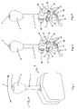
- Fig. 1 shows a schematic isometric view of an embodiment of an actuator according to the present invention. In this embodiment, it is an actuator for an automated vehicle transmission.
- a shift lever actuator 1 which is arranged along the dashed line 2 relative to a base portion 3 pivotally.
- the shift lever 1 can thus be moved back and forth in the direction of travel, so as to select, for example, the various switching stages of an automatic transmission.
- buttons 5 can be further functions of the motor vehicle control, for example, so that the parking brake of the automatic transmission is engaged, or the engine of the motor vehicle can be started and stopped.
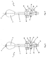
- FIGS. 2 and 3 show the actuator according to Fig. 1 , where in the representations of the FIGS. 2 and 3 the arranged in the base region 3 of the actuator housing has been removed to make the operation of the transmission device and the signaling device 8 of the actuator recognizable.
- arranged in the knob 4 pushbutton 5 is connected via a disposed within the shaft 7 of the shift lever 1 (not visible) transmission linkage with a U-shaped rocker arm 8.
- the rocker arm 8 is pivotally mounted by means of a bolt 9 in the lower region of the shift lever shaft 7 on the shift lever 1.
- the above the Swing lever 8 recognizable sockets 10 represent the storage of the shift lever 1, to the pivotal movement of the shift lever 2 according to FIG Fig. 1 takes place.
- the rocker arm 8 has in the central region of its legs 11 each have a slot 12 which is penetrated by a transmission pin, which in turn is connected to the lower end of the transmission linkage in the shift lever shaft 7.
- the transmission device thus formed causes the rocker arm 8 is pivoted by pressing the arranged in the lever knob 4 pushbutton 5 via transmission linkage, transmission pin and slots 12 down.
- the oscillating lever 8 carries in the region of its transverse axis opposite the oscillating axis 9 a permanent magnet 13, which serves to trigger the magnetic sensor or Hall sensor formed as a signal generator 6 of the actuator.
- the push button 5 is shown in the depressed position, which is spent on the transmission linkage, transmission pin, slot 12 and rocker arm 8, the permanent magnet 13 of the rocker arm 8 in the region of the magnetic sensor 6.
- the magnetic sensor 6 triggers an electrical or electronic signal, which can be transmitted to the corresponding switching receiver.
- detectable signal generator 14 serve the position detection of the shift lever 1 and the generation of the corresponding electrical or electronic switching signals.
- shift lever 1 is a shift lever, which automatically returns to the center position after each operation.
- the shift lever 1 at its lower end to a functional contour 15, in which engages a spring-loaded roller 16 such that the shift lever 1 always returns after releasing due to the spring action of the roller 16 connected to the leaf spring 17 back to the upright center position ,
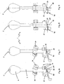
- the 4 and 5 show the actuator according to the Fig. 1 to 3 again in the rear view (relative to the direction of travel of a motor vehicle equipped with the actuator). It shows Fig. 4 Pushbutton 5, transmission linkage and rocker arm 8 in the neutral position, while the same elements in Fig. 5 are each shown in the operating position.
- Fig. 6 to 9 show a further embodiment of an actuator according to the present invention.
- Actuator shown is also the operation of a shift-by-wire gearbox, or an automatic transmission of a motor vehicle.
- the embodiment according to Fig. 6 to 9 differs from the embodiment according to Fig. 1 to 5 in particular in that the transmission of the switching signal from the pushbutton 5 to the here designed as a microswitch 18 signal generator in the embodiment according to Fig. 6 to 9 not contactless, but rather takes place by means of a transmission pin connected to the transmission link 19.
- microswitch 18 and transfer pin 19 are formed so that a triggering of the microswitch 18 can be made only in the neutral center position of the shift lever 1.
- This embodiment is not part of the invention.
- the transmission pin 19 or the trigger 20 of the microswitch 18 can also be readily configured such that a transmission of the switching signal from the pushbutton 5 can also take place in the actuating position of the shift lever 1 deflected from the center position.
- either the transmission pin 19 of the transmission linkage, or the trigger 20 of the microswitch 18 - or else both elements 19 and 20 - are provided, for example with a (not shown) Auslöserkufe, regardless of the current relative angular position between microswitch 18 attached to the base region 3, the transmission of the switching signal from the push button 5 on the micro switch 18 allowed.
- a magnetic sensor arrangement 14 emerges which, together with a permanent magnet arranged in the lower region of the shift lever 1, serves to detect the respective instantaneous position of the shift lever 1. Furthermore, goes from the Fig. 6 to 9 also again connected to the lower end of the shift lever 1 functional contour 15, which together with the spring-loaded roller 16 ensures that the shift lever 1 returns to each switching operation again in the center position.
- the invention provides an actuating device for technical systems, in particular for gear change transmissions of motor vehicles, in which an actuating element arranged on the additional switching element can be made particularly robust and low-interference.
- the invention eliminates the known from the prior art disadvantages in terms of sensitive cable management to the additional switching element, as well as with respect to the exposed attachment associated with insufficient protection of the contactor. The invention thus makes a contribution to the long-term safe operation of technical systems, in particular in the application in the field of motor vehicle systems or transmission actuation.
Landscapes
- Engineering & Computer Science (AREA)
- General Engineering & Computer Science (AREA)
- Mechanical Engineering (AREA)
- Arrangement Or Mounting Of Control Devices For Change-Speed Gearing (AREA)
- Gear-Shifting Mechanisms (AREA)
- Switch Cases, Indication, And Locking (AREA)
- Control Of Transmission Device (AREA)
Claims (13)
- Dispositif actionneur pour un système technique, par exemple pour la sélection d'étages de commutation d'une boîte de vitesses à changement de rapports électrique dite shift-by-wire, le dispositif actionneur comprenant un élément actionneur (1) mobile par rapport à une partie de socle (3), ayant au moins deux positions de commutation au moins un élément de commutation supplémentaire (5) et un dispositif émetteur de signal (8) étant agencés sur l'élément actionneur (1), l'élément de commutation supplémentaire (5) et le dispositif émetteur de signal (8) étant reliés l'un à l'autre par l'intermédiaire d'un dispositif transmetteur mécanique de manière telle que, lorsqu'on appuie sur l'élément de commutation supplémentaire, le dispositif émetteur de signal soit déplacé et coopère, indépendamment de la position relative du levier actionneur (1), avec un émetteur de signal (6, 14, 18) fixé dans la partie de socle (3), de manière à permettre la transmission d'un signal de commutation du bouton poussoir (5) à l'émetteur de signal (6, 14, 18).
- Dispositif actionneur selon la revendication 1,
où l'émetteur de signal (6) est un capteur à effet Hall. - Dispositif actionneur selon la revendication 1,
où l'émetteur de signal (6) est un détecteur optique. - Dispositif actionneur selon la revendication 1,
où l'émetteur de signal est un micro-rupteur (18). - Dispositif actionneur selon l'une des revendications 1 à 4,
où un déclencheur (20) du micro-rupteur (18) et/ou une tige de transmission (19) est pourvu(e) d'un patin de déclenchement destiné à déclencher le micro-rupteur (18). - Dispositif actionneur selon l'une des revendications 1 à 4,
où l'élément actionneur (1) est un levier de commutation. - Dispositif actionneur selon l'une des revendications 1 à 4,
où l'élément actionneur est un contacteur rotatif. - Dispositif actionneur selon l'une des revendications 1 à 4,
où l'élément actionneur est un contacteur coulissant. - Dispositif actionneur selon l'une des revendications 1 à 8,
où l'élément de commutation supplémentaire (5) est un bouton poussoir ou commutateur poussoir. - Dispositif actionneur selon l'une des revendications 1 à 9,
où l'élément de commutation supplémentaire est un contacteur à bascule ou un contacteur coulissant. - Dispositif actionneur selon l'une des revendications 1 à 10,
où l'élément actionneur (1) est un levier sélecteur d'une boîte de vitesses d'un véhicule automobile. - Dispositif actionneur selon l'une des revendications 1 à 11,
où l'élément de commutation supplémentaire (5) est configuré pour enclencher une position P d'une boîte de vitesses automatique d'un véhicule automobile. - Dispositif actionneur selon l'une des revendications 1 à 12,
où l'élément de commutation supplémentaire (5) est configuré pour démarrer et/ou arrêter le moteur d'un véhicule automobile.
Applications Claiming Priority (2)
| Application Number | Priority Date | Filing Date | Title |
|---|---|---|---|
| DE102005044254A DE102005044254A1 (de) | 2005-09-15 | 2005-09-15 | Betätigungseinrichtung mit Zusatzschaltelement |
| PCT/DE2006/001645 WO2007031075A1 (fr) | 2005-09-15 | 2006-09-15 | Dispositif de commande a element de commutation supplementaire |
Publications (2)
| Publication Number | Publication Date |
|---|---|
| EP1924788A1 EP1924788A1 (fr) | 2008-05-28 |
| EP1924788B1 true EP1924788B1 (fr) | 2009-12-02 |
Family
ID=37635732
Family Applications (1)
| Application Number | Title | Priority Date | Filing Date |
|---|---|---|---|
| EP06805301A Not-in-force EP1924788B1 (fr) | 2005-09-15 | 2006-09-15 | Dispositif de commande a element de commutation supplementaire |
Country Status (6)
| Country | Link |
|---|---|
| US (1) | US8752448B2 (fr) |
| EP (1) | EP1924788B1 (fr) |
| JP (1) | JP5215854B2 (fr) |
| DE (2) | DE102005044254A1 (fr) |
| ES (1) | ES2334063T3 (fr) |
| WO (1) | WO2007031075A1 (fr) |
Families Citing this family (13)
| Publication number | Priority date | Publication date | Assignee | Title |
|---|---|---|---|---|
| JP4986742B2 (ja) * | 2007-06-28 | 2012-07-25 | 株式会社アツミテック | 車両用変速操作装置 |
| DE102008010397A1 (de) * | 2008-02-21 | 2009-08-27 | GM Global Technology Operations, Inc., Detroit | Gangwahlhebel |
| DE102010002020A1 (de) * | 2010-02-17 | 2011-08-18 | Deere & Company, Ill. | Vorrichtung zur Steuerung einer Parksperre für ein Kraftfahrzeug |
| JP2011235798A (ja) | 2010-05-12 | 2011-11-24 | Bosch Corp | チェンジレバーの位置検出装置および自動変速機の変速制御装置 |
| CN101936385A (zh) * | 2010-08-25 | 2011-01-05 | 常州东风农机集团有限公司 | 拖拉机起动和换挡安全保护机构 |
| DE102010042942B4 (de) * | 2010-10-26 | 2012-10-31 | Preh Gmbh | Schwenkbedienelement mit verbesserter Ruhestellung |
| DE102011087330A1 (de) * | 2011-11-29 | 2013-05-29 | Bayerische Motoren Werke Aktiengesellschaft | Betätigungsvorrichtung für ein Getriebe eines Kraftfahrzeugs |
| DE102013219924A1 (de) * | 2013-10-01 | 2015-04-02 | Zf Friedrichshafen Ag | Wählhebel für ein Automatgetriebe oder ein automatisiertes Schaltgetriebe eines Kraftfahrzeugs |
| US9019053B1 (en) * | 2013-12-09 | 2015-04-28 | Raymond Contreras | Multi-position magnetic rotary switch |
| US10107388B2 (en) * | 2015-12-16 | 2018-10-23 | Dura Operating, Llc | Vehicle shifter assembly |
| JP6391632B2 (ja) * | 2016-07-28 | 2018-09-19 | 株式会社東海理化電機製作所 | シフト装置 |
| KR101836701B1 (ko) * | 2016-09-23 | 2018-03-08 | 현대자동차주식회사 | 전자식 변속시스템용 레버장치 |
| US11073205B2 (en) | 2019-03-29 | 2021-07-27 | Dus Operating Inc. | Shift lever assembly with position sensing |
Family Cites Families (26)
| Publication number | Priority date | Publication date | Assignee | Title |
|---|---|---|---|---|
| JPS57118930A (en) * | 1981-01-16 | 1982-07-24 | Nissan Motor Co Ltd | Engine starting circuit for vehicle with automatic transmission unit |
| JPS57192827U (fr) * | 1981-06-02 | 1982-12-07 | ||
| JPS5825731U (ja) * | 1981-07-27 | 1983-02-18 | トヨタ自動車株式会社 | 自動変速機のシフトレバ装置 |
| DE3238219A1 (de) * | 1982-10-15 | 1984-04-19 | Wabco Westinghouse Fahrzeugbremsen GmbH, 3000 Hannover | Hilfskraftbetaetigtes getriebe |
| DE3434205A1 (de) * | 1984-09-18 | 1986-03-27 | Wabco Westinghouse Fahrzeugbremsen GmbH, 3000 Hannover | Geber fuer ein schaltgetriebe eines kraftfahrzeugs |
| US4774850A (en) * | 1987-08-24 | 1988-10-04 | Regal Plastics Company | Gear shifter cartridge |
| JPH0181835U (fr) * | 1987-11-24 | 1989-05-31 | ||
| US5220984A (en) * | 1992-04-20 | 1993-06-22 | Grand Haven Stamped Products Company, (Div. Of Jsj Corporation) | Shift mechanism |
| JPH0650415A (ja) * | 1992-07-28 | 1994-02-22 | Fuji Kiko Co Ltd | シフトレバー装置 |
| JP3076170B2 (ja) * | 1993-05-17 | 2000-08-14 | 株式会社東海理化電機製作所 | 自動変速機のシフト操作装置 |
| US5718312A (en) * | 1993-05-18 | 1998-02-17 | Grand Haven Stamped Products, Div. Of Jsj Corporation | Vehicle park/lock mechanism with control module having a locking mechanism and a control switch actuated by the locking mechanism |
| JP3329534B2 (ja) * | 1993-10-20 | 2002-09-30 | 株式会社東海理化電機製作所 | シフトレバー装置 |
| US5489246A (en) * | 1994-08-29 | 1996-02-06 | Pontiac Coil, Inc. | Electronic park lock |
| US5845534A (en) * | 1997-05-15 | 1998-12-08 | Hyundai Motor Company | Selector level assembly for an automatic transmission of a vehicle |
| DE19747269A1 (de) * | 1997-10-25 | 1999-04-29 | Bayerische Motoren Werke Ag | Kraftfahrzeug |
| DE19821403B4 (de) * | 1998-05-13 | 2005-07-28 | ZF Lemförder Metallwaren AG | Wählvorrichtung für ein Fahrzeuggetriebe |
| FR2784061B1 (fr) * | 1998-10-02 | 2000-10-27 | Renault | Transmission comportant un capteur a effet hall |
| DE10025357B4 (de) * | 2000-05-23 | 2006-02-16 | Lisa Dräxlmaier GmbH | Gangschalthebel modularen Aufbaus mit Schaltmodul |
| US6695090B2 (en) * | 2001-02-15 | 2004-02-24 | Motorcycle Riders Holdings Corp. | Back-lit handlebar control assembly |
| JP2004017951A (ja) * | 2002-06-12 | 2004-01-22 | Ep Room:Kk | アクセルを解除するブレーキ装置 |
| DE10247068A1 (de) * | 2002-10-09 | 2004-04-22 | ZF Lemförder Metallwaren AG | Fahrstufen-Eingabeeinheit |
| JP2004310299A (ja) * | 2003-04-03 | 2004-11-04 | Sony Corp | ジョイスティック装置 |
| DE10315644B4 (de) * | 2003-04-04 | 2005-04-21 | ZF Lemförder Metallwaren AG | Monostabile Schaltung mit P-Position |
| DE10315643B3 (de) * | 2003-04-04 | 2004-10-28 | ZF Lemförder Metallwaren AG | Shift by wire-Schaltung mit P-Position |
| JP4384539B2 (ja) * | 2004-05-06 | 2009-12-16 | 株式会社東海理化電機製作所 | シフトレバー |
| DE102005043288A1 (de) * | 2005-09-09 | 2007-03-15 | Leopold Kostal Gmbh & Co. Kg | Elektrische Schalteinrichtung für ein Kraftfahrzeug |
-
2005
- 2005-09-15 DE DE102005044254A patent/DE102005044254A1/de not_active Ceased
-
2006
- 2006-09-15 DE DE502006005537T patent/DE502006005537D1/de active Active
- 2006-09-15 ES ES06805301T patent/ES2334063T3/es active Active
- 2006-09-15 US US12/066,858 patent/US8752448B2/en not_active Expired - Fee Related
- 2006-09-15 JP JP2008530326A patent/JP5215854B2/ja not_active Expired - Fee Related
- 2006-09-15 WO PCT/DE2006/001645 patent/WO2007031075A1/fr not_active Ceased
- 2006-09-15 EP EP06805301A patent/EP1924788B1/fr not_active Not-in-force
Also Published As
| Publication number | Publication date |
|---|---|
| US8752448B2 (en) | 2014-06-17 |
| JP2009507706A (ja) | 2009-02-26 |
| US20080282829A1 (en) | 2008-11-20 |
| DE102005044254A1 (de) | 2007-03-29 |
| ES2334063T3 (es) | 2010-03-04 |
| DE502006005537D1 (de) | 2010-01-14 |
| JP5215854B2 (ja) | 2013-06-19 |
| WO2007031075A1 (fr) | 2007-03-22 |
| EP1924788A1 (fr) | 2008-05-28 |
Similar Documents
| Publication | Publication Date | Title |
|---|---|---|
| DE4407005C1 (de) | Fahrpedaleinrichtung | |
| EP1631759B1 (fr) | Dispositif de selection du rapport permettant la transmission sans couplage mecanique de commandes de changement de vitesses a une boite de vitesses automatique d'un vehicule automobile | |
| EP2126419B1 (fr) | Dispositif d'actionnement à mécanisme de retour du levier de sélection | |
| EP1924788B1 (fr) | Dispositif de commande a element de commutation supplementaire | |
| DE102014116581B4 (de) | Mechanismus zum rückführen eines fahrzeuggetriebes in eine park-stellung und fahrzeug mit einem solchen mechanismus | |
| EP2188550B1 (fr) | Dispositif d'actionnement doté d'un blocage du coulisseau de changement de rapport | |
| EP1848903B2 (fr) | Dispositif electrique de changement de vitesse pour un vehicule automobile | |
| EP1190190B1 (fr) | Dispositif de changement de vitesses pour une boite de vehicule automobile | |
| EP1111275B1 (fr) | Commande de sélection de gamme avec déverrouillage de secours pour un frein de stationnement | |
| EP1922500A1 (fr) | Dispositif electrique de changement de vitesses pour un vehicule a moteur | |
| DE10022433B4 (de) | Wählhebelvorrichtung | |
| DE69814030T2 (de) | Schalthebel | |
| EP1611376B1 (fr) | Changement de vitesses du type shift-by-wire avec position p | |
| DE10361209B3 (de) | Vorrichtung zum Umschalten eines mechanischen Schaltmittels | |
| EP2122204A1 (fr) | Dispositif de commutation électrique pour un véhicule à moteur | |
| DE102018121207A1 (de) | Fahrzeugschaltvorrichtung | |
| DE69501812T2 (de) | Steuerung einer Feststellbremse und eines Getriebes | |
| DE102007053689A1 (de) | Druck- und drehbetätigbares Bedienelement für ein Kraftfahrzeug | |
| EP1082557A1 (fr) | Dispositif de transmission pour vehicules | |
| DE102016122344A1 (de) | Betätigungseinrichtung für ein elektromechanisches oder hydromechanisches Kraftfahrzeuggetriebe insbesondere eines landwirtschaftlichen Nutzfahrzeugs | |
| DE19711560C2 (de) | Im Bereich der Lenksäule eines Fahrzeuges angeordneter Schalter | |
| EP2163793A1 (fr) | Dispositif d'actionnement destiné à la commutation d'un engrenage et à l'activation d'un frein de stationnement | |
| DE102009033569A1 (de) | Handschalthebelbaugruppe für ein Fahrzeuggetriebe | |
| WO1997004252A1 (fr) | Dispositif de selection pour boite automatique de vitesses | |
| DE102017100849B3 (de) | Anordnung mit einem Wählhebel eines Fahrzeuggetriebes und einer mit dem Wählhebel zusammenwirkenden Wählhebelrückstellvorrichtung |
Legal Events
| Date | Code | Title | Description |
|---|---|---|---|
| PUAI | Public reference made under article 153(3) epc to a published international application that has entered the european phase |
Free format text: ORIGINAL CODE: 0009012 |
|
| 17P | Request for examination filed |
Effective date: 20080126 |
|
| AK | Designated contracting states |
Kind code of ref document: A1 Designated state(s): DE ES FR GB IT SE |
|
| 17Q | First examination report despatched |
Effective date: 20080731 |
|
| RBV | Designated contracting states (corrected) |
Designated state(s): DE ES FR GB IT SE |
|
| GRAP | Despatch of communication of intention to grant a patent |
Free format text: ORIGINAL CODE: EPIDOSNIGR1 |
|
| GRAS | Grant fee paid |
Free format text: ORIGINAL CODE: EPIDOSNIGR3 |
|
| GRAA | (expected) grant |
Free format text: ORIGINAL CODE: 0009210 |
|
| AK | Designated contracting states |
Kind code of ref document: B1 Designated state(s): DE ES FR GB IT SE |
|
| REG | Reference to a national code |
Ref country code: GB Ref legal event code: FG4D Free format text: NOT ENGLISH |
|
| REF | Corresponds to: |
Ref document number: 502006005537 Country of ref document: DE Date of ref document: 20100114 Kind code of ref document: P |
|
| REG | Reference to a national code |
Ref country code: ES Ref legal event code: FG2A Ref document number: 2334063 Country of ref document: ES Kind code of ref document: T3 |
|
| REG | Reference to a national code |
Ref country code: SE Ref legal event code: TRGR |
|
| PLBE | No opposition filed within time limit |
Free format text: ORIGINAL CODE: 0009261 |
|
| STAA | Information on the status of an ep patent application or granted ep patent |
Free format text: STATUS: NO OPPOSITION FILED WITHIN TIME LIMIT |
|
| 26N | No opposition filed |
Effective date: 20100903 |
|
| PGFP | Annual fee paid to national office [announced via postgrant information from national office to epo] |
Ref country code: SE Payment date: 20100913 Year of fee payment: 5 |
|
| PGFP | Annual fee paid to national office [announced via postgrant information from national office to epo] |
Ref country code: GB Payment date: 20100916 Year of fee payment: 5 |
|
| PGFP | Annual fee paid to national office [announced via postgrant information from national office to epo] |
Ref country code: ES Payment date: 20101018 Year of fee payment: 5 |
|
| GBPC | Gb: european patent ceased through non-payment of renewal fee |
Effective date: 20110915 |
|
| REG | Reference to a national code |
Ref country code: SE Ref legal event code: EUG |
|
| PG25 | Lapsed in a contracting state [announced via postgrant information from national office to epo] |
Ref country code: GB Free format text: LAPSE BECAUSE OF NON-PAYMENT OF DUE FEES Effective date: 20110915 |
|
| PGFP | Annual fee paid to national office [announced via postgrant information from national office to epo] |
Ref country code: IT Payment date: 20120918 Year of fee payment: 7 Ref country code: FR Payment date: 20120926 Year of fee payment: 7 |
|
| PG25 | Lapsed in a contracting state [announced via postgrant information from national office to epo] |
Ref country code: SE Free format text: LAPSE BECAUSE OF NON-PAYMENT OF DUE FEES Effective date: 20110916 |
|
| REG | Reference to a national code |
Ref country code: ES Ref legal event code: FD2A Effective date: 20131029 |
|
| PG25 | Lapsed in a contracting state [announced via postgrant information from national office to epo] |
Ref country code: ES Free format text: LAPSE BECAUSE OF NON-PAYMENT OF DUE FEES Effective date: 20110916 |
|
| REG | Reference to a national code |
Ref country code: FR Ref legal event code: ST Effective date: 20140530 |
|
| PG25 | Lapsed in a contracting state [announced via postgrant information from national office to epo] |
Ref country code: FR Free format text: LAPSE BECAUSE OF NON-PAYMENT OF DUE FEES Effective date: 20130930 Ref country code: IT Free format text: LAPSE BECAUSE OF NON-PAYMENT OF DUE FEES Effective date: 20130915 |
|
| PGFP | Annual fee paid to national office [announced via postgrant information from national office to epo] |
Ref country code: DE Payment date: 20150908 Year of fee payment: 10 |
|
| REG | Reference to a national code |
Ref country code: DE Ref legal event code: R119 Ref document number: 502006005537 Country of ref document: DE |
|
| PG25 | Lapsed in a contracting state [announced via postgrant information from national office to epo] |
Ref country code: DE Free format text: LAPSE BECAUSE OF NON-PAYMENT OF DUE FEES Effective date: 20170401 |