EP1925238A1 - Armature pour une armoire angulaire et armoire angulaire - Google Patents
Armature pour une armoire angulaire et armoire angulaire Download PDFInfo
- Publication number
- EP1925238A1 EP1925238A1 EP07019000A EP07019000A EP1925238A1 EP 1925238 A1 EP1925238 A1 EP 1925238A1 EP 07019000 A EP07019000 A EP 07019000A EP 07019000 A EP07019000 A EP 07019000A EP 1925238 A1 EP1925238 A1 EP 1925238A1
- Authority
- EP
- European Patent Office
- Prior art keywords
- lever
- tray
- fitting according
- pivot axis
- fitting
- Prior art date
- Legal status (The legal status is an assumption and is not a legal conclusion. Google has not performed a legal analysis and makes no representation as to the accuracy of the status listed.)
- Granted
Links
Images


Classifications
-
- A—HUMAN NECESSITIES
- A47—FURNITURE; DOMESTIC ARTICLES OR APPLIANCES; COFFEE MILLS; SPICE MILLS; SUCTION CLEANERS IN GENERAL
- A47B—TABLES; DESKS; OFFICE FURNITURE; CABINETS; DRAWERS; GENERAL DETAILS OF FURNITURE
- A47B49/00—Revolving cabinets or racks; Cabinets or racks with revolving parts
- A47B49/004—Cabinets with compartments provided with trays revolving on a vertical axis
- A47B49/006—Corner cabinets
-
- A—HUMAN NECESSITIES
- A47—FURNITURE; DOMESTIC ARTICLES OR APPLIANCES; COFFEE MILLS; SPICE MILLS; SUCTION CLEANERS IN GENERAL
- A47B—TABLES; DESKS; OFFICE FURNITURE; CABINETS; DRAWERS; GENERAL DETAILS OF FURNITURE
- A47B81/00—Cabinets or racks specially adapted for other particular purposes, e.g. for storing guns or skis
- A47B81/002—Corner cabinets; Cabinets designed for being placed in a corner or a niche
Definitions
- the invention relates to a fitting for a corner cabinet, in particular causaleck 2, with a cabinet body and accessible via a corner door interior in which at least one tray by means of a fitting between an inner position and an outer position in which the tray at least partially over a plane of a door opening of the Eck Wes out, is movably guided, wherein the fitting for controlling the Tablarterrorism between the inner and outer position has a hinged at a first storage position on the tray first lever assembly and at a spaced from the first bearing second bearing point hinged to the tray second lever assembly.
- a fitting of this kind is from the DE 20 2004 011 200 U1 in which a respective tray of two articulated on its underside of the handlebars is supported, wherein the first link is pivotable about a pivot axis of a support column and the second link about an axis parallel to the pivot axis of the support column axis of a support bearing.
- the tray is controlled by both handlebars together between the inner and the outer position.
- the object of the invention is to provide a fitting of the type mentioned, in which the corner cabinet available standing space is optimally used by corresponding dimensioning of the tray.
- the fitting according to the invention is characterized in that at least one of the lever arrangements is designed such that the distance between its bearing point and a stationary pivot axis of the lever arrangement changes in the tablature movement between the inner and the outer position.
- the tableau movement takes place by superimposing two circular path movements respectively executed around the respective pivot axes. Ultimately, this results in a between the inner and outer position of the tray performed S-shaped tabla movement.
- the circular pivoting movements of the respective rigid links cause the interior of the corner cabinet relatively much space is required when panning. This means that the tray must be relatively small dimensions so as not to hang on the inner walls of the corner cabinet when pivoting the handlebars.
- the movement kinematics of the tabla movement known from the prior art is thus accompanied by relatively small-sized trays. Accordingly, of course, the footprint for abdovde objects is small.
- the tray is moved by the fitting according to the invention by providing at least one variable-length lever such that a large and thus relatively much space-claiming "Aushol Gay" is prevented within the corner cabinet.
- the tray can be dimensioned larger overall. Accordingly enlarged Of course, the footprint for ablindde objects.
- each tray two lever assemblies are provided with variable lever length or per tray a lever assembly with variable lever length and a so-called “rigid” lever assembly, in which the distance between the bearing point and the pivot axis in the Tablar Gaylor not changes, that is constant.
- the at least one tray does not carry a relatively much space-claiming "Ausholzi" within the corner cabinet, is also prevented by the fact that the two lever assemblies are pivotally mounted in each case about an arranged near the door opening or arranged pivot axis.
- the two pivot axes can be superimposed or coincide.
- the two lever arrangements can thus be mounted pivotably about a common pivot axis.
- each of the lever arrangements is associated with a separate pivot axis, wherein the two pivot axes are close to each other in the vicinity of the door opening.
- the lever arrangements are pivotally mounted about a common pivot axis.
- At least one of the lever arrangements has a sliding guide on which its bearing point is articulated relative to the pivot axis in a relatively displaceable manner on the tray.
- At least one of the lever arrangements is assigned a control unit for the control the distance between its bearing point and the pivot axis and thus the relative position of the tray in the Tablarterrorism between the inner and the outer position.
- the control unit may have at least one control cam located in the vicinity of the pivot axis, on which the lever end of the associated lever arrangement is guided in a controlled manner. If each tray two lever assemblies are provided with variable lever length, each lever assembly may be associated with a control cam.
- At least one of the lever arrangements at least two levers, of which a first lever is pivotally mounted on the pivot axis and serves as part of the sliding guide for a second lever, hinged on the one hand at the second bearing point on the tray and at the same time slidably on first lever is guided and on the other hand is connected to a located at the Tablarterrorism with a constant distance from the pivot axis pivotally connected to the first lever and at the same time guided controlled with its lever end on the control cam.
- the second lever is preferably designed as a toggle lever.
- the lever arrangement can thus form a so-called "four-joint arrangement".
- the intake and / or extraction device can have at least one energy store, which is arranged between two parts of the corner cabinet that are movable relative to one another during the tray movement.
- the relatively movable points may be located on one of the lever arrangements. Alternatively, it would be possible to attach the relatively movable points on the one hand on the cabinet periphery and on the other hand on one of the lever arrangements.
- the combination of retraction and extension of the energy storage of the retraction device also serves as a force storage of the extension device simultaneously.
- the energy accumulator is formed by a spring unit.
- a spring unit for example, at least one coil spring and / or at least one gas spring comes into consideration.
- a damping device for damping the Tablarterrorism when retracting into the inner position and / or extension is provided in the outer position.
- the damping device can be arranged or arranged between two positions of the corner cupboard which are movable relative to one another during the tabletting movement.
- one of the lever arrangements is suitable for this purpose.
- the invention also comprises a corner cabinet with the features of independent claim 16.
- the corner cabinet according to the invention is characterized in that at least one of the lever arrangements is designed in this way is that changes the distance between its bearing point and a fixed pivot axis of the lever assembly in the Tablarmony between the inner and outer position.
- FIGS. 1 to 10 show a preferred embodiment of the invention Eck Os 11 and the built-in inventive fitting 12.
- the corner cabinet 11 has a cabinet body 13, which is exemplified with Rechtekkigem floor plan.
- the cabinet body 13 in turn consists of a rear wall 14, two side walls 15, 16 and a front side 17, which in turn is subdivided into a front wall 18 and a corner cabinet door 19 arranged adjacent thereto. Furthermore, a cabinet bottom 29 is provided.
- Front wall 18 and corner door 19 occupy the front 17 in approximately equal parts.
- the rectangular cabinet body 13 defines a correspondingly rectangular interior 20, which is accessible in about half the corner cabinet door 19. As a rule, further cabinet parts are attached to the front wall 18 and to the side wall 15 adjacent to the door opening.
- a Door opening of the corner cupboard 11 protrudes is controlled movably.
- a single shelf 21 is accommodated in the corner cabinet 11.
- two or more superimposed shelves could be arranged in the corner cupboard 11, preferably in their respective inner or outer position are aligned over one another.
- the tray 21 is exemplified in one-piece embodiment. However, it is also possible to use multi-part trays.
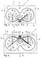
- the floor plan of the tray 21 is exemplified in the form of an eight.
- two substantially circular tray sections 23a, 23b are provided, which are interconnected via a smaller diameter intermediate section 24.
- the tray 21 is fitted in the middle, so to speak.
- the sidecut is therefore provided so that the tray 21 in the tableau movement described below in more detail without hindrance from the cabinet periphery out of the door opening and can go beyond the adjoining the door opening side wall 15 out into the open position.
- the tray 21 is supported at a first bearing point 25 by a first lever arrangement 26 and at a second bearing point 27 spaced from the first bearing point 25 by a second lever arrangement 28.
- the lever arrangements 26, 28 are mounted at their respective bearing points 25, 27 articulated on the underside of the tray 21.
- Both lever assemblies 26, 28 are pivotally connected according to the illustrated embodiment on the one hand to a common stationary, located near the door opening pivot axis 30 and on the other hand at the associated bearing point 25, 27 articulated to the tray 21.
- both lever assemblies 26, 28 are formed such that the distance between their respective bearing point 25, 27 and the pivot axis 30 in the Tablarterrorism between the inner and outer position changes. That is, the lever length of the lever assemblies 26, 28 shortened or extended during the tableau movement.
- one of the lever assemblies is equipped with variable lever length, while in the other lever assembly, the distance between its bearing on the shelf and the pivot axis in the Tablar Gay Gay Gay Gay), which is hinged to the bearing on the tray.
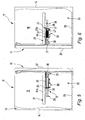
- the pivot axis 30 is located on a particular plate-like support unit 31, which in turn is attached via a fastener 32 on the bottom of the cabinet 29, on an upper cabinet cover or on the inside of the front wall 18, in particular there on a vertical strut 33.
- a fastener 32 on the bottom of the cabinet 29, on an upper cabinet cover or on the inside of the front wall 18, in particular there on a vertical strut 33.
- a respective lever arrangement 26, 28 has two levers 36, 37, of which a first lever 36 is pivotally mounted on the pivot axis 30 and serves as part of a sliding guide for a second lever 37.
- the second lever 37 is hinged to the associated bearing point 25, 27 on the tray 21 and at the same time displaceably guided on the first lever 36, wherein it is on the other hand hingedly connected to the first lever 36 at a located in the Tablarterrorism at a constant distance from the pivot axis 30 hinge point 38 and simultaneously guided with its lever end 39 on the associated control cam 34, 35.
- the second lever 37 is hinged to the tray 21 as already mentioned.
- the first lever 36 may be tubular; on which a kind of guide bushing 41 is movably guided, which in turn is connected to the second lever 37.
- the second lever 37 is designed as a toggle lever and has a second lever arm 44, which is articulated on the one hand on the guide bush 41 and the other hand connected via a hinge point 43 with a first lever arm 42, in turn, on the other hand articulated via the hinge point 38 to the first lever 36 is.
- this situation is the same on both lever assemblies 26, 28, ie
- Each lever assembly is associated with a control cam 34, 35, whose eccentric curves control the distance between the respective bearing points 25, 27 and the pivot axis 30 during the Tablarterrorism between the inner and outer position.
- a retraction device 46 for supporting or autonomous execution of a directed from the outer to the inner position of the tray 21 closing movement and / or a Auszug raised to support or autonomous execution of a directed from the inner to the outer position of the tray 21 opening movement intended.
- the retraction device 46 is also the extraction device according to the preferred embodiment.
- the entry and exit device 46 has at least one energy store in the form of a spring unit 47, which is arranged between two in the Tablarterrorism relatively movable points of the corner cabinet 11.
- At least one helical spring is provided in a preferred manner, on the one hand fixed to the first lever 36, for example, attached to a pivot point 38 carrier plate 48, and on the other hand with the associated bearing point 25, 27 coupled to the guide bush 41, for example ,
- the respective cam 34, 35 has, as mentioned, an eccentric curve with a dead center 49, which causes the lever length after shortening from the dead center again extended. This is done both in the Tablarterrorism from the inner to the outer position and in the Tablarterrorism from the outer to the inner position.
- the coil spring is thus stretched or relaxed when shortening or lengthening the lever length, which results in that the spring force of the coil spring is provided to support or autonomous execution of Tablariolo in the inner position and support or independent execution of Tablarterrorism in the outer position.
- the damping device 50 for damping the Tablarterrorism when entering the inner position and / or extending into the outer position.
- the damping device 50 can be arranged between two positions of the corner cabinet 11 which are movable relative to one another during the tableau movement, for example, also being fixedly connected on one side to the first lever 36 and 27 on the other hand being movably coupled to the associated bearing point 25, 27.
- the Damping device 50 has a damping cylinder 51, which in turn has a cylinder housing 52 and a slidably mounted therein damping piston 53, which in turn is connected to a piston rod 54 which at the piston remote end to the first lever 36, in particular as the coil spring to the support plate 48, attached is.
- the damping piston 53 In the tabla movement, the damping piston 53 is either extended or retracted into the cylinder housing 52, whereby the air contained therein is displaced during the extension of the damping piston 53, which leads to the damping of the tableau movement.
- FIGS. 10A to 10D the movement situation of the tray 21 is illustrated in the Tablarnism between the inner and the outer position.
- the tray 21 is initially in the inner position, completely housed in the interior 20 of the corner cupboard 11.
- the corner cabinet door 19 is opened and the tray 21 is pulled out a little bit with its door opening next tray section 23 b from the door opening.
- FIG. 10B shows.
- the lever length of both the first and the second lever arrangement 26, 28 shortens.
- the distance between the two bearing points 25, 27 to the pivot axis 30 is thus reduced.
- the coil spring of the spring unit 47 is tensioned, that is, a total must be worked against this spring force.
- the tray then reaches the in FIG. 10C shown position in which the dead centers of the respective, the lever assemblies 26, 28 associated control cams 34, 35 are already run over.
- the lever lengths of the two lever assemblies 26, 28 have therefore extended again, ie, the distance between the respective bearing points 25, 27 and the pivot axis 30 has become larger again.
- the coil spring of the spring unit 47 relaxes and provides previously stored spring force for the movement of the tray in the Figure 10D shown external position available. In this external position more than half of the tray 21 is arranged outside the corner cupboard 11. The determination of this external position is done, inter alia, that the run on the control cams 34, 35 guide pin to the end of the cams 34, 35 reach where there is a stop beyond which a further movement is not possible. In the outer position of the toggle lever of the first lever assembly 26 is almost stretched and thus has its largest lever length. The distance of the associated bearing point 25 to the pivot axis 30 is greatest in this position.
Landscapes
- Combinations Of Kitchen Furniture (AREA)
- Bay Windows, Entrances, And Structural Adjustments Related Thereto (AREA)
- Assembled Shelves (AREA)
- Cabinets, Racks, Or The Like Of Rigid Construction (AREA)
- Hinges (AREA)
Applications Claiming Priority (1)
| Application Number | Priority Date | Filing Date | Title |
|---|---|---|---|
| DE102006055806A DE102006055806A1 (de) | 2006-11-27 | 2006-11-27 | Beschlag für einen Eckschrank und Eckschrank |
Publications (2)
| Publication Number | Publication Date |
|---|---|
| EP1925238A1 true EP1925238A1 (fr) | 2008-05-28 |
| EP1925238B1 EP1925238B1 (fr) | 2009-08-12 |
Family
ID=39144370
Family Applications (1)
| Application Number | Title | Priority Date | Filing Date |
|---|---|---|---|
| EP07019000A Not-in-force EP1925238B1 (fr) | 2006-11-27 | 2007-09-27 | Armature pour une armoire angulaire et armoire angulaire |
Country Status (3)
| Country | Link |
|---|---|
| EP (1) | EP1925238B1 (fr) |
| AT (1) | ATE439064T1 (fr) |
| DE (2) | DE102006055806A1 (fr) |
Cited By (6)
| Publication number | Priority date | Publication date | Assignee | Title |
|---|---|---|---|---|
| WO2011042213A1 (fr) * | 2009-10-05 | 2011-04-14 | Compagnucci Holding S.P.A. | Armoire comportant une ou plusieurs étagères extractibles |
| EP2353440A1 (fr) * | 2010-02-05 | 2011-08-10 | Hetal-Werke Franz Hettich GmbH & Co. KG | Armature pour une armoire de coin et armoire de coin |
| EP2353441A1 (fr) * | 2010-02-05 | 2011-08-10 | Hetal-Werke Franz Hettich GmbH & Co. KG | Armature pour une armoire de coin |
| US20120049708A1 (en) * | 2010-02-05 | 2012-03-01 | Hetal-Werke Franz Hettich Gmbh & Co. Kg | Fitting for a Corner Cupboard and a Corner Cupboard |
| US20140225492A1 (en) * | 2011-05-23 | 2014-08-14 | Kesseböhmer Holding e.K. | Fitting for corner cabinets and pull-in device for said type of fitting |
| DE202016004737U1 (de) * | 2016-08-02 | 2017-11-03 | Hetal-Werke Franz Hettich Gmbh & Co. Kg | Beschlag für einen Eckschrank |
Families Citing this family (6)
| Publication number | Priority date | Publication date | Assignee | Title |
|---|---|---|---|---|
| IT1393242B1 (it) * | 2009-03-17 | 2012-04-12 | Sige S P A | Mobile con ripiano estraibile. |
| DE202010002231U1 (de) | 2010-02-05 | 2010-05-20 | Hetal-Werke Franz Hettich Gmbh & Co. Kg | Beschlag für einen Eckschrank und Eckschrank |
| EP3326491A1 (fr) | 2016-11-29 | 2018-05-30 | Vauth-Sagel Holding GmbH & Co. KG | Ferrure destinée au logement mobile commandé par engrenage d'une étagère dans un élément d'angle |
| EP3572188B1 (fr) | 2018-05-23 | 2020-10-07 | Wezag GmbH Werkzeugfabrik | Outil à pince manuel |
| DE102019113251A1 (de) * | 2019-05-20 | 2020-11-26 | Paul Hettich Gmbh & Co. Kg | Möbelelement |
| DE102022122884A1 (de) | 2022-09-08 | 2024-03-14 | Kesseböhmer Holding Kg | Auszugvorrichtung für einen Schrank, insbesondere einen Eckschrank |
Citations (3)
| Publication number | Priority date | Publication date | Assignee | Title |
|---|---|---|---|---|
| US4582372A (en) * | 1982-06-04 | 1986-04-15 | Cooper William E | Bi-axial shelf with retractable guidance and support system |
| DE202004011200U1 (de) * | 2004-07-16 | 2005-12-01 | Heinrich J. Kesseböhmer KG | Eckschrank, insbesondere Kücheneckschrank |
| DE202005016432U1 (de) * | 2005-10-20 | 2005-12-22 | Vauth-Sagel Holding Gmbh & Co. Kg | Schwenkauszug aus einem Eckschrank |
Family Cites Families (3)
| Publication number | Priority date | Publication date | Assignee | Title |
|---|---|---|---|---|
| DE7234174U (de) * | 1972-12-14 | Fa H Kesseboehmer | Schwenkkorb für Eckschränke | |
| DE19860241B4 (de) * | 1998-12-24 | 2008-02-28 | Hetal-Werke Franz Hettich Gmbh & Co | Karussellvorrichtung zum Halten mindestens eines Fachbodens in einem Eckschrank und einer zweiflügeligen Türe |
| DE20306002U1 (de) * | 2003-04-15 | 2003-12-11 | Vauth-Sagel GmbH & Co. Grundstücksverwaltung | Eckschrank mit verschieblichen Einbauelementen |
-
2006
- 2006-11-27 DE DE102006055806A patent/DE102006055806A1/de not_active Ceased
-
2007
- 2007-09-27 AT AT07019000T patent/ATE439064T1/de active
- 2007-09-27 DE DE502007001285T patent/DE502007001285D1/de active Active
- 2007-09-27 EP EP07019000A patent/EP1925238B1/fr not_active Not-in-force
Patent Citations (3)
| Publication number | Priority date | Publication date | Assignee | Title |
|---|---|---|---|---|
| US4582372A (en) * | 1982-06-04 | 1986-04-15 | Cooper William E | Bi-axial shelf with retractable guidance and support system |
| DE202004011200U1 (de) * | 2004-07-16 | 2005-12-01 | Heinrich J. Kesseböhmer KG | Eckschrank, insbesondere Kücheneckschrank |
| DE202005016432U1 (de) * | 2005-10-20 | 2005-12-22 | Vauth-Sagel Holding Gmbh & Co. Kg | Schwenkauszug aus einem Eckschrank |
Cited By (8)
| Publication number | Priority date | Publication date | Assignee | Title |
|---|---|---|---|---|
| WO2011042213A1 (fr) * | 2009-10-05 | 2011-04-14 | Compagnucci Holding S.P.A. | Armoire comportant une ou plusieurs étagères extractibles |
| EP2353440A1 (fr) * | 2010-02-05 | 2011-08-10 | Hetal-Werke Franz Hettich GmbH & Co. KG | Armature pour une armoire de coin et armoire de coin |
| EP2353441A1 (fr) * | 2010-02-05 | 2011-08-10 | Hetal-Werke Franz Hettich GmbH & Co. KG | Armature pour une armoire de coin |
| US20120049708A1 (en) * | 2010-02-05 | 2012-03-01 | Hetal-Werke Franz Hettich Gmbh & Co. Kg | Fitting for a Corner Cupboard and a Corner Cupboard |
| US8911035B2 (en) * | 2010-02-05 | 2014-12-16 | Hetal-Werke Franz Hettich Gmbh & Co. Kg | Fitting for a corner cupboard and a corner cupboard |
| US20140225492A1 (en) * | 2011-05-23 | 2014-08-14 | Kesseböhmer Holding e.K. | Fitting for corner cabinets and pull-in device for said type of fitting |
| US9119470B2 (en) * | 2011-05-23 | 2015-09-01 | Kesseböhmer Holding e.K. | Fitting for corner cabinets and pull-in device for said type of fitting |
| DE202016004737U1 (de) * | 2016-08-02 | 2017-11-03 | Hetal-Werke Franz Hettich Gmbh & Co. Kg | Beschlag für einen Eckschrank |
Also Published As
| Publication number | Publication date |
|---|---|
| ATE439064T1 (de) | 2009-08-15 |
| DE102006055806A1 (de) | 2008-05-29 |
| EP1925238B1 (fr) | 2009-08-12 |
| DE502007001285D1 (de) | 2009-09-24 |
Similar Documents
| Publication | Publication Date | Title |
|---|---|---|
| EP1925238B1 (fr) | Armature pour une armoire angulaire et armoire angulaire | |
| EP1925237A2 (fr) | Armature pour une armoire angulaire et armoire angulaire | |
| EP1925239B1 (fr) | Armoire de coin | |
| EP3087866B1 (fr) | Armature pour une armoire angulaire et armoire angulaire dotée d'une armature | |
| EP3707330B1 (fr) | Armature d'ouvrant pour un meuble, paroi latérale d'un corps de meuble et meuble doté d'une paroi latérale | |
| EP2841668B1 (fr) | Ferrure de porte | |
| EP3314079B1 (fr) | Dispositif d'ejection pour porte pliante ou pour porte pliante et coulissante | |
| EP2702219B1 (fr) | Meuble doté d'un corps et un clapet pliant | |
| DE102015106917B4 (de) | Möbelscharnier mit einem Dämpfer und einer Feder | |
| EP3527762A1 (fr) | Charnière à plusieurs articulations | |
| EP2092850B1 (fr) | Armature pour une armoire de coin | |
| EP2268882A1 (fr) | Charnière de meuble | |
| EP1964490B1 (fr) | Armoire d'angle, en particulier armoire d'angle de cuisine | |
| DE202010000096U1 (de) | Halteelement zum Verstellen eines Deckels eines Möbels | |
| AT527779B1 (de) | Möbel mit einem Möbelkorpus und einer geführten Klappe | |
| EP1999328B1 (fr) | Porte-clapet pour clapet de meuble | |
| AT508351B1 (de) | Dämpfungseinheit sowie faltbare zusatzplatte und tisch | |
| EP2064971A1 (fr) | Armature pour armoire angulaire | |
| DE202010002232U1 (de) | Beschlaganordnung für einen Eckschrank | |
| EP3547876B1 (fr) | Ferrure destinée au logement mobile commandé par roulement d'une étagère dans un élément d'angle | |
| DE202010002230U1 (de) | Beschlag für einen Eckschrank und Eckschrank | |
| DE202005020863U1 (de) | Dämpfeinrichtung für schwenkbare Möbelteile | |
| EP2191745A1 (fr) | Armature pour une armoire angulaire | |
| DE10234797B4 (de) | Beschlag für einen Eckschrank | |
| EP3278689A1 (fr) | Armature pour une armoire angulaire |
Legal Events
| Date | Code | Title | Description |
|---|---|---|---|
| PUAI | Public reference made under article 153(3) epc to a published international application that has entered the european phase |
Free format text: ORIGINAL CODE: 0009012 |
|
| 17P | Request for examination filed |
Effective date: 20080411 |
|
| AK | Designated contracting states |
Kind code of ref document: A1 Designated state(s): AT BE BG CH CY CZ DE DK EE ES FI FR GB GR HU IE IS IT LI LT LU LV MC MT NL PL PT RO SE SI SK TR |
|
| AX | Request for extension of the european patent |
Extension state: AL BA HR MK RS |
|
| AKX | Designation fees paid |
Designated state(s): AT BE BG CH CY CZ DE DK EE ES FI FR GB GR HU IE IS IT LI LT LU LV MC MT NL PL PT RO SE SI SK TR |
|
| GRAP | Despatch of communication of intention to grant a patent |
Free format text: ORIGINAL CODE: EPIDOSNIGR1 |
|
| GRAS | Grant fee paid |
Free format text: ORIGINAL CODE: EPIDOSNIGR3 |
|
| GRAA | (expected) grant |
Free format text: ORIGINAL CODE: 0009210 |
|
| AK | Designated contracting states |
Kind code of ref document: B1 Designated state(s): AT BE BG CH CY CZ DE DK EE ES FI FR GB GR HU IE IS IT LI LT LU LV MC MT NL PL PT RO SE SI SK TR |
|
| REG | Reference to a national code |
Ref country code: GB Ref legal event code: FG4D Free format text: NOT ENGLISH |
|
| REG | Reference to a national code |
Ref country code: CH Ref legal event code: EP Ref country code: CH Ref legal event code: NV Representative=s name: TROESCH SCHEIDEGGER WERNER AG |
|
| REG | Reference to a national code |
Ref country code: IE Ref legal event code: FG4D |
|
| REF | Corresponds to: |
Ref document number: 502007001285 Country of ref document: DE Date of ref document: 20090924 Kind code of ref document: P |
|
| PGFP | Annual fee paid to national office [announced via postgrant information from national office to epo] |
Ref country code: AT Payment date: 20090922 Year of fee payment: 3 |
|
| LTIE | Lt: invalidation of european patent or patent extension |
Effective date: 20090812 |
|
| PG25 | Lapsed in a contracting state [announced via postgrant information from national office to epo] |
Ref country code: FI Free format text: LAPSE BECAUSE OF FAILURE TO SUBMIT A TRANSLATION OF THE DESCRIPTION OR TO PAY THE FEE WITHIN THE PRESCRIBED TIME-LIMIT Effective date: 20090812 Ref country code: SE Free format text: LAPSE BECAUSE OF FAILURE TO SUBMIT A TRANSLATION OF THE DESCRIPTION OR TO PAY THE FEE WITHIN THE PRESCRIBED TIME-LIMIT Effective date: 20090812 Ref country code: LT Free format text: LAPSE BECAUSE OF FAILURE TO SUBMIT A TRANSLATION OF THE DESCRIPTION OR TO PAY THE FEE WITHIN THE PRESCRIBED TIME-LIMIT Effective date: 20090812 Ref country code: IS Free format text: LAPSE BECAUSE OF FAILURE TO SUBMIT A TRANSLATION OF THE DESCRIPTION OR TO PAY THE FEE WITHIN THE PRESCRIBED TIME-LIMIT Effective date: 20091212 Ref country code: ES Free format text: LAPSE BECAUSE OF FAILURE TO SUBMIT A TRANSLATION OF THE DESCRIPTION OR TO PAY THE FEE WITHIN THE PRESCRIBED TIME-LIMIT Effective date: 20091123 |
|
| NLV1 | Nl: lapsed or annulled due to failure to fulfill the requirements of art. 29p and 29m of the patents act | ||
| PG25 | Lapsed in a contracting state [announced via postgrant information from national office to epo] |
Ref country code: LV Free format text: LAPSE BECAUSE OF FAILURE TO SUBMIT A TRANSLATION OF THE DESCRIPTION OR TO PAY THE FEE WITHIN THE PRESCRIBED TIME-LIMIT Effective date: 20090812 Ref country code: SI Free format text: LAPSE BECAUSE OF FAILURE TO SUBMIT A TRANSLATION OF THE DESCRIPTION OR TO PAY THE FEE WITHIN THE PRESCRIBED TIME-LIMIT Effective date: 20090812 Ref country code: PL Free format text: LAPSE BECAUSE OF FAILURE TO SUBMIT A TRANSLATION OF THE DESCRIPTION OR TO PAY THE FEE WITHIN THE PRESCRIBED TIME-LIMIT Effective date: 20090812 Ref country code: NL Free format text: LAPSE BECAUSE OF FAILURE TO SUBMIT A TRANSLATION OF THE DESCRIPTION OR TO PAY THE FEE WITHIN THE PRESCRIBED TIME-LIMIT Effective date: 20090812 |
|
| REG | Reference to a national code |
Ref country code: IE Ref legal event code: FD4D |
|
| BERE | Be: lapsed |
Owner name: HETAL-WERKE FRANZ HETTICH G.M.B.H. & CO. KG Effective date: 20090930 |
|
| PG25 | Lapsed in a contracting state [announced via postgrant information from national office to epo] |
Ref country code: PT Free format text: LAPSE BECAUSE OF FAILURE TO SUBMIT A TRANSLATION OF THE DESCRIPTION OR TO PAY THE FEE WITHIN THE PRESCRIBED TIME-LIMIT Effective date: 20091212 Ref country code: BG Free format text: LAPSE BECAUSE OF FAILURE TO SUBMIT A TRANSLATION OF THE DESCRIPTION OR TO PAY THE FEE WITHIN THE PRESCRIBED TIME-LIMIT Effective date: 20091112 |
|
| PG25 | Lapsed in a contracting state [announced via postgrant information from national office to epo] |
Ref country code: DK Free format text: LAPSE BECAUSE OF FAILURE TO SUBMIT A TRANSLATION OF THE DESCRIPTION OR TO PAY THE FEE WITHIN THE PRESCRIBED TIME-LIMIT Effective date: 20090812 Ref country code: CZ Free format text: LAPSE BECAUSE OF FAILURE TO SUBMIT A TRANSLATION OF THE DESCRIPTION OR TO PAY THE FEE WITHIN THE PRESCRIBED TIME-LIMIT Effective date: 20090812 Ref country code: EE Free format text: LAPSE BECAUSE OF FAILURE TO SUBMIT A TRANSLATION OF THE DESCRIPTION OR TO PAY THE FEE WITHIN THE PRESCRIBED TIME-LIMIT Effective date: 20090812 Ref country code: MC Free format text: LAPSE BECAUSE OF NON-PAYMENT OF DUE FEES Effective date: 20090930 Ref country code: IE Free format text: LAPSE BECAUSE OF FAILURE TO SUBMIT A TRANSLATION OF THE DESCRIPTION OR TO PAY THE FEE WITHIN THE PRESCRIBED TIME-LIMIT Effective date: 20090812 Ref country code: RO Free format text: LAPSE BECAUSE OF FAILURE TO SUBMIT A TRANSLATION OF THE DESCRIPTION OR TO PAY THE FEE WITHIN THE PRESCRIBED TIME-LIMIT Effective date: 20090812 |
|
| PG25 | Lapsed in a contracting state [announced via postgrant information from national office to epo] |
Ref country code: SK Free format text: LAPSE BECAUSE OF FAILURE TO SUBMIT A TRANSLATION OF THE DESCRIPTION OR TO PAY THE FEE WITHIN THE PRESCRIBED TIME-LIMIT Effective date: 20090812 |
|
| PLBE | No opposition filed within time limit |
Free format text: ORIGINAL CODE: 0009261 |
|
| STAA | Information on the status of an ep patent application or granted ep patent |
Free format text: STATUS: NO OPPOSITION FILED WITHIN TIME LIMIT |
|
| REG | Reference to a national code |
Ref country code: FR Ref legal event code: ST Effective date: 20100531 |
|
| 26N | No opposition filed |
Effective date: 20100517 |
|
| PG25 | Lapsed in a contracting state [announced via postgrant information from national office to epo] |
Ref country code: FR Free format text: LAPSE BECAUSE OF NON-PAYMENT OF DUE FEES Effective date: 20091012 |
|
| PG25 | Lapsed in a contracting state [announced via postgrant information from national office to epo] |
Ref country code: BE Free format text: LAPSE BECAUSE OF NON-PAYMENT OF DUE FEES Effective date: 20090930 |
|
| PG25 | Lapsed in a contracting state [announced via postgrant information from national office to epo] |
Ref country code: GR Free format text: LAPSE BECAUSE OF FAILURE TO SUBMIT A TRANSLATION OF THE DESCRIPTION OR TO PAY THE FEE WITHIN THE PRESCRIBED TIME-LIMIT Effective date: 20091113 |
|
| PGFP | Annual fee paid to national office [announced via postgrant information from national office to epo] |
Ref country code: DE Payment date: 20100806 Year of fee payment: 4 |
|
| PG25 | Lapsed in a contracting state [announced via postgrant information from national office to epo] |
Ref country code: LU Free format text: LAPSE BECAUSE OF NON-PAYMENT OF DUE FEES Effective date: 20090927 Ref country code: MT Free format text: LAPSE BECAUSE OF FAILURE TO SUBMIT A TRANSLATION OF THE DESCRIPTION OR TO PAY THE FEE WITHIN THE PRESCRIBED TIME-LIMIT Effective date: 20090812 |
|
| PG25 | Lapsed in a contracting state [announced via postgrant information from national office to epo] |
Ref country code: HU Free format text: LAPSE BECAUSE OF FAILURE TO SUBMIT A TRANSLATION OF THE DESCRIPTION OR TO PAY THE FEE WITHIN THE PRESCRIBED TIME-LIMIT Effective date: 20100213 |
|
| PG25 | Lapsed in a contracting state [announced via postgrant information from national office to epo] |
Ref country code: TR Free format text: LAPSE BECAUSE OF FAILURE TO SUBMIT A TRANSLATION OF THE DESCRIPTION OR TO PAY THE FEE WITHIN THE PRESCRIBED TIME-LIMIT Effective date: 20090812 |
|
| PG25 | Lapsed in a contracting state [announced via postgrant information from national office to epo] |
Ref country code: CY Free format text: LAPSE BECAUSE OF FAILURE TO SUBMIT A TRANSLATION OF THE DESCRIPTION OR TO PAY THE FEE WITHIN THE PRESCRIBED TIME-LIMIT Effective date: 20090812 |
|
| PGFP | Annual fee paid to national office [announced via postgrant information from national office to epo] |
Ref country code: IT Payment date: 20110922 Year of fee payment: 5 |
|
| REG | Reference to a national code |
Ref country code: CH Ref legal event code: PL |
|
| GBPC | Gb: european patent ceased through non-payment of renewal fee |
Effective date: 20110927 |
|
| PG25 | Lapsed in a contracting state [announced via postgrant information from national office to epo] |
Ref country code: LI Free format text: LAPSE BECAUSE OF NON-PAYMENT OF DUE FEES Effective date: 20110930 Ref country code: CH Free format text: LAPSE BECAUSE OF NON-PAYMENT OF DUE FEES Effective date: 20110930 |
|
| PG25 | Lapsed in a contracting state [announced via postgrant information from national office to epo] |
Ref country code: GB Free format text: LAPSE BECAUSE OF NON-PAYMENT OF DUE FEES Effective date: 20110927 |
|
| PG25 | Lapsed in a contracting state [announced via postgrant information from national office to epo] |
Ref country code: DE Free format text: LAPSE BECAUSE OF NON-PAYMENT OF DUE FEES Effective date: 20130403 |
|
| PG25 | Lapsed in a contracting state [announced via postgrant information from national office to epo] |
Ref country code: IT Free format text: LAPSE BECAUSE OF NON-PAYMENT OF DUE FEES Effective date: 20120927 |
|
| REG | Reference to a national code |
Ref country code: DE Ref legal event code: R119 Ref document number: 502007001285 Country of ref document: DE Effective date: 20130403 |
|
| REG | Reference to a national code |
Ref country code: AT Ref legal event code: MM01 Ref document number: 439064 Country of ref document: AT Kind code of ref document: T Effective date: 20120927 |
|
| PG25 | Lapsed in a contracting state [announced via postgrant information from national office to epo] |
Ref country code: AT Free format text: LAPSE BECAUSE OF NON-PAYMENT OF DUE FEES Effective date: 20120927 |