EP1925388A1 - Scie circulaire à table - Google Patents
Scie circulaire à table Download PDFInfo
- Publication number
- EP1925388A1 EP1925388A1 EP07016041A EP07016041A EP1925388A1 EP 1925388 A1 EP1925388 A1 EP 1925388A1 EP 07016041 A EP07016041 A EP 07016041A EP 07016041 A EP07016041 A EP 07016041A EP 1925388 A1 EP1925388 A1 EP 1925388A1
- Authority
- EP
- European Patent Office
- Prior art keywords
- protective hood
- saw blade
- saw
- work table
- saw according
- Prior art date
- Legal status (The legal status is an assumption and is not a legal conclusion. Google has not performed a legal analysis and makes no representation as to the accuracy of the status listed.)
- Granted
Links
Images

Classifications
-
- B—PERFORMING OPERATIONS; TRANSPORTING
- B23—MACHINE TOOLS; METAL-WORKING NOT OTHERWISE PROVIDED FOR
- B23D—PLANING; SLOTTING; SHEARING; BROACHING; SAWING; FILING; SCRAPING; LIKE OPERATIONS FOR WORKING METAL BY REMOVING MATERIAL, NOT OTHERWISE PROVIDED FOR
- B23D45/00—Sawing machines or sawing devices with circular saw blades or with friction saw discs
- B23D45/06—Sawing machines or sawing devices with circular saw blades or with friction saw discs with a circular saw blade arranged underneath a stationary work-table
-
- B—PERFORMING OPERATIONS; TRANSPORTING
- B27—WORKING OR PRESERVING WOOD OR SIMILAR MATERIAL; NAILING OR STAPLING MACHINES IN GENERAL
- B27G—ACCESSORY MACHINES OR APPARATUS FOR WORKING WOOD OR SIMILAR MATERIALS; TOOLS FOR WORKING WOOD OR SIMILAR MATERIALS; SAFETY DEVICES FOR WOOD WORKING MACHINES OR TOOLS
- B27G19/00—Safety guards or devices specially adapted for wood saws; Auxiliary devices facilitating proper operation of wood saws
- B27G19/02—Safety guards or devices specially adapted for wood saws; Auxiliary devices facilitating proper operation of wood saws for circular saws
- B27G19/025—Safety guards or devices specially adapted for wood saws; Auxiliary devices facilitating proper operation of wood saws for circular saws with guards for tool
-
- B—PERFORMING OPERATIONS; TRANSPORTING
- B27—WORKING OR PRESERVING WOOD OR SIMILAR MATERIAL; NAILING OR STAPLING MACHINES IN GENERAL
- B27G—ACCESSORY MACHINES OR APPARATUS FOR WORKING WOOD OR SIMILAR MATERIALS; TOOLS FOR WORKING WOOD OR SIMILAR MATERIALS; SAFETY DEVICES FOR WOOD WORKING MACHINES OR TOOLS
- B27G19/00—Safety guards or devices specially adapted for wood saws; Auxiliary devices facilitating proper operation of wood saws
- B27G19/08—Accessories for keeping open the saw kerf, e.g. riving knives or wedge plates
Definitions
- the invention relates to a table saw with a work table, a rotatably driven saw blade with a ring gear, which is mounted below the work table, and wherein a processing portion of the saw blade passes through the work table and a riving knife, which is arranged on the work table and on which a protective hood for at least Partial cover of the machining portion of the saw blade is pivotally mounted about a pivot axis, from a with its free end a cutting region of the ring gear of the machining portion of the saw blade substantially completely covering the rest position into an operating position in which at least one intersection of the Sprocket of the machining portion of the saw blade for machining a workpiece is uncovered.
- the DE 103 48 587 B3 a table saw with a protective cover for the saw blade and a cover plate attached to the side of the protective cover. This is to ensure that the saw blade is also covered laterally by the cover plate to cover even the lower part of the saw blade.
- the US Pat. No. 6,405,624 B2 a protective hood, which can be pivoted from a first to a second position, wherein in the second position, the processing area of a table saw blade is not covered by the protective hood.
- a similar design shows the DE 202 09 464 U1 , Describing a table saw machine, in the riving knife a height-adjustable mounted protective hood is executed, which includes in the lowest position the projecting beyond the table part of the circular saw blade substantially, the height adjustment of the guard is designed so that the lower edge of the guard always parallel remains aligned to the table surface.
- the above describes US Pat. No. 6,405,624 B2 a protective hood in which a rotational pivoting of the protective hood is also made possible.
- the cited prior art has the disadvantage that in a rest position, the protective cover can be damaged quickly by acting on them lateral forces, as the free In this case, the end of the guard dodges the lateral forces, which can lead to breakage or deformation of the guard.
- the invention therefore has the task of providing a circular table saw of the generic type, in which the forces acting on the guard transverse forces in the rest position do not lead to deformation of the guard or its attachment to the riving knife.
- the invention solves this problem by a table-top circular saw, in which engages in the rest position, a portion of the free end of the guard in a corresponding recess in the work table.
- the guard is designed so that in its fully lowered, namely the rest position corresponding position in which the guard normally rests against the work table, the guard has an area which enters into a space provided for this purpose the work table, so that the free end of the protective hood is fixed with respect to transverse forces acting on the protective hood. This means that the protective cover is not in the lowered position on the work table, but at least partially immersed in this.
- the protective hood can be designed such that it has a substantially U-shaped profile which covers the upper edge of the toothed rim of the saw blade, but also the two side surfaces of the saw blade.
- the U-shaped profile is also closed at the free end of the protective cover, so that in the rest position the saw blade completely covered by the protective cover with respect to its sprocket becomes.
- the protective hood can protrude in the direction of the free end over the ring gear of the saw blade. This may possibly be dispensed with, to close the free end of the guard with respect to the U-shaped profile.
- the protective cover is integrally formed.
- the one-piece design has the advantage that the protective cover can be made relatively simple. The guard is then pivoted with respect to their entirety about the pivot axis which is fixed on the riving knife.
- the protective cover is formed in two parts, wherein the first part is pivotally mounted on the splitting wedge and substantially corresponds to the one-piece protective hood.
- the second part is then pivotable about a parallel to the pivot axis of the first part extending axis and this is located at the free end of the first part of the guard.
- the area which engages in the rest position in the work table be provided on the first and / or on the second part of the protective hood.
- a pivoting of the second part take place in such a way that the second part is pivoted into the first part in order to clear a cutting region of the saw blade for processing.
- a design with a movable second front part of the guard allows a better enclosure of the cutting area, which also offers particular advantages, provided that a Staubabsaug noisy is provided, which is attached to the guard, preferably in the region of articulation of the guard on the riving knife, wherein provident a second pivotable part of the guard by the better Enclosing the saw blade, the suction of the rear, namely the cutting area facing away from the part of the ring gear, dust raised can be improved and so the chip removal is improved by the dust extraction.
- the protective hood consists at least partially of plastic and is preferably at least partially transparent. It is particularly advantageous if this consists of a machinable and impact-resistant plastic. If this is at least partially transparent, such a design allows a good view of the tool both in the resting and in the processing situation.
- the parts of the protective cover may consist of PC.
- the protective hood or the second part of the protective hood has a run-on slope at its free end.
- a pivoting movement of the protective hood or of the part of the protective hood is facilitated if a workpiece to be machined is pushed against the protective hood.
- the guard then moves under the pressure of the workpiece from the rest position into a processing position, it being possible to provide that the run-on slope can be formed both straight and curved.
- the protective hood can be preloaded in particular in the direction of the rest position, in particular due to its own weight, but also in addition, for example, by spring force, so as to release only the necessary cutting area of the saw blade and immediately swing back into the rest position after processing.
- the protective hood and the two parts of the protective hood can have different shapes.
- the protective hood will have a polygonal shape, which tapers in particular starting from its free end to its end mounted on the riving knife end.
- a shape corresponding to the shape of a sword of a sailboat may be provided as a form of the protective hood in a side view.
- the saw blade is adjustable relative to the work table in height and / or inclination.
- the protective hood is arranged so far above the splitting wedge and mounted pivotably, that the various adjustment options of the saw blade are allowed.
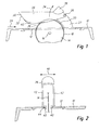
- FIG. 1 shows a table saw according to the invention with a work table 10, a table insert 12 with a Slit for the passage of a saw blade 14 includes.
- the saw blade 14 is rotatably mounted below the work table 10 about an axis 16. It comprises on its outer periphery a ring gear 18, wherein by the portion of the saw blade 14, which is arranged above the work table 10, a processing section 20 is formed.
- the saw blade 14 is rotatably driven by means of a motor, not shown.
- a riving knife 22 is also attached, which serves to split machined workpieces.
- the processing direction or feed direction for workpieces is indicated here by the arrow 24.
- the workpieces are pushed in the direction of arrow 24 against the saw blade 14 and separated by the saw blade, with a further splitting then takes place by the workpiece runs against the riving knife 22 and is divided by this in two halves.
- a protective cover 26 is also provided, which is pivotally mounted on the riving knife 22 via an axis 28.
- the protective hood 26 has in the side view the shape of a sword of a sailboat and tapers in the direction of the pivot axis 28.
- the guard At its free end 30, the guard on a run-on slope 32, which allows pivoting of the guard when coming against the guard 26 workpieces .
- the protective hood is pivoted in the direction of the arrow 34 about the axis 28 and thus releases a part of a cutting region, which is designated 36 in the drawing, in which region the workpiece can then be processed by the saw blade.
- a dust extraction device 38 is provided on the protective hood 26, by means of which the dust and / or particulate matter thrown upwards and forwards by the saw blade, in particular the section area of the saw blade, can be collected and removed.
- Figure 2 shows a sectional view of a table saw according to Figure 1 in a rest position.
- the same components are provided here with the same reference numerals.
- the protective hood 26 is shown in the lowered representation.
- the protective hood 26 has a region which is designated by 40 in FIG.
- the region 40 in the U-shaped cross-sectional view of the protective hood in FIG. 2 consists of a partial region of the two lower edges of the protective hood 26, wherein they have a smaller distance from one another in the region 40 than the two lateral surfaces 42 of the protective hood.
- the protective cover 26 now engages in the slot 44 of the insert 12 of the work table, so that the lower edge of the protective hood 26 is stabilized over the region 40 against transverse loads, which are identified by the arrow 46.
- the protective hood 26 has already been lowered again, that is to say through the cutting area guided workpiece, a better completion of the saw blade through the protective hood, so that the suction of whirled up dust, which is transported by the saw blade 14 to the front, is improved.
- FIG. 3 now shows a further embodiment, the same reference numbers being used for the same components here as well.
- the work table is here designed according to Figure 1.
- the protective hood 26 is a two-part protective hood 26 comprising a first part 50 and a second part 52 configured.
- the first part 50 is again pivotably mounted on the riving knife 22 via a pivot axis 28.
- the first part 50 also carries the dust extraction.
- the second part 52 is now articulated, which is designed pivotable about an axis 54 with respect to the first part 50.
- the first 50 and second 52 parts each have a U-shaped cross-sectional shape, as can be seen in particular Figure 4, and has in side view the shape of a sword of a sailboat, both parts 50 and 52 to its pivot axis 28 and 54 rejuvenate.
- FIG. 4 shows the design according to FIG. 3 in section from the front comprising a first part 50 of a protective hood 26 and a second part 52 of the protective hood 26.
- the second part 52 of the protective hood 26 is rotatably mounted on the first part 50 via two pins 56, wherein the pins 56 form the axis 54.
- the area 40 which engages in the slot 44 in contrast to Figure 1 is not designed as a continuation of the legs of a U-shaped cross-sectional configuration of the protective hood 26 and the part 52, but has a portion 48 which in the direction of the saw blade 14 is bent over. In this way an even better finish and better sealing of the saw blade 14 from the environment can be achieved.
- a load direction by transverse forces, in particular of the first part 50 is indicated by the arrow 60.
- the invention thus has the advantage that the sprocket can be kept closed as long as possible and that better collected by the rear ascending sprocket forward thrown dust or particulate matter and can be dissipated via a chip and dust extraction.
- the guard 26 laterally stabilized considerably.
Landscapes
- Life Sciences & Earth Sciences (AREA)
- Engineering & Computer Science (AREA)
- Mechanical Engineering (AREA)
- Wood Science & Technology (AREA)
- Forests & Forestry (AREA)
- Sawing (AREA)
Applications Claiming Priority (1)
| Application Number | Priority Date | Filing Date | Title |
|---|---|---|---|
| DE102006055018A DE102006055018B3 (de) | 2006-11-22 | 2006-11-22 | Tischkreissäge |
Publications (2)
| Publication Number | Publication Date |
|---|---|
| EP1925388A1 true EP1925388A1 (fr) | 2008-05-28 |
| EP1925388B1 EP1925388B1 (fr) | 2012-07-11 |
Family
ID=38542625
Family Applications (1)
| Application Number | Title | Priority Date | Filing Date |
|---|---|---|---|
| EP07016041A Active EP1925388B1 (fr) | 2006-11-22 | 2007-08-16 | Scie circulaire à table |
Country Status (2)
| Country | Link |
|---|---|
| EP (1) | EP1925388B1 (fr) |
| DE (1) | DE102006055018B3 (fr) |
Cited By (4)
| Publication number | Priority date | Publication date | Assignee | Title |
|---|---|---|---|---|
| EP2260987A1 (fr) * | 2009-06-09 | 2010-12-15 | Metabowerke GmbH | Scie circulaire à table avec couverture de copeaux |
| US20110179923A1 (en) * | 2010-01-27 | 2011-07-28 | Tsuda Hollan A | Blade guard with dust collection |
| US20190240750A1 (en) * | 2018-02-08 | 2019-08-08 | Yongkang Congzhen Tools Co.,Ltd | Stage dedusting shield for dust-free table saw |
| US20200180186A1 (en) * | 2015-12-16 | 2020-06-11 | Black & Decker Inc. | Tile saw |
Families Citing this family (9)
| Publication number | Priority date | Publication date | Assignee | Title |
|---|---|---|---|---|
| EP2108491B8 (fr) * | 2008-04-08 | 2012-09-26 | Suva | Capot protecteur pour une scie circulaire |
| CN201783703U (zh) * | 2010-08-06 | 2011-04-06 | 浙江世达工具制造有限公司 | 复合锯台切式台面防护罩 |
| CN105235029A (zh) * | 2015-10-29 | 2016-01-13 | 浙江培瑞工具有限公司 | 台锯用防护罩 |
| DE102017111070A1 (de) * | 2017-05-22 | 2018-11-22 | Festool Gmbh | Schutzabdeckung für eine Säge und damit ausgestattete Säge |
| CN111958688B (zh) * | 2017-12-20 | 2022-04-08 | 福建杜氏木业有限公司 | 一种安全实用的锯木装置 |
| DE202018102266U1 (de) | 2018-04-24 | 2018-04-30 | Avola Maschinenfabrik A. Volkenborn Gmbh & Co.Kg | Schutzvorrichtung für Tischkreissägen |
| DE102019200366A1 (de) | 2019-01-14 | 2020-07-16 | Festool Gmbh | Sägeblattabdeckung, Anschlagseinheit und Tischsäge |
| DE202019101274U1 (de) | 2019-03-07 | 2019-03-12 | Avola Maschinenfabrik A. Volkenborn Gmbh & Co. Kg | Schutzvorrichtung für Trennscheibe |
| DE202020101184U1 (de) | 2020-03-04 | 2020-03-12 | Avola Maschinenfabrik A. Volkenborn Gmbh + Co. Kg | Schutzvorrichtung für Trennscheibe |
Citations (6)
| Publication number | Priority date | Publication date | Assignee | Title |
|---|---|---|---|---|
| US1563317A (en) * | 1923-09-22 | 1925-12-01 | Westinghouse Electric & Mfg Co | Saw guard |
| US1594772A (en) * | 1924-08-05 | 1926-08-03 | Charles N Fournier | Rotary saw guard |
| GB662756A (en) * | 1948-12-10 | 1951-12-12 | Arthur Wilfred Hunt | Improvements in or relating to safety guards for power operated machine tools |
| NL6703368A (fr) * | 1967-02-28 | 1968-08-29 | ||
| US20010035081A1 (en) * | 1998-07-08 | 2001-11-01 | Stephen O. Sutton | Splitter and cutting member guard assembly |
| DE10348587B3 (de) * | 2003-08-18 | 2005-03-03 | P & F Brother Industrial Corp. | Tischkreissäge mit einer Schutzhaube für das Sägeblatt sowie einer neigbaren auf der Schutzhaube angebrachten Abdeckplatte |
Family Cites Families (2)
| Publication number | Priority date | Publication date | Assignee | Title |
|---|---|---|---|---|
| DE229211C (fr) * | ||||
| DE20209464U1 (de) * | 2002-06-19 | 2003-10-30 | Metabowerke GmbH, 72622 Nürtingen | Tischkreissägemaschine |
-
2006
- 2006-11-22 DE DE102006055018A patent/DE102006055018B3/de not_active Expired - Fee Related
-
2007
- 2007-08-16 EP EP07016041A patent/EP1925388B1/fr active Active
Patent Citations (6)
| Publication number | Priority date | Publication date | Assignee | Title |
|---|---|---|---|---|
| US1563317A (en) * | 1923-09-22 | 1925-12-01 | Westinghouse Electric & Mfg Co | Saw guard |
| US1594772A (en) * | 1924-08-05 | 1926-08-03 | Charles N Fournier | Rotary saw guard |
| GB662756A (en) * | 1948-12-10 | 1951-12-12 | Arthur Wilfred Hunt | Improvements in or relating to safety guards for power operated machine tools |
| NL6703368A (fr) * | 1967-02-28 | 1968-08-29 | ||
| US20010035081A1 (en) * | 1998-07-08 | 2001-11-01 | Stephen O. Sutton | Splitter and cutting member guard assembly |
| DE10348587B3 (de) * | 2003-08-18 | 2005-03-03 | P & F Brother Industrial Corp. | Tischkreissäge mit einer Schutzhaube für das Sägeblatt sowie einer neigbaren auf der Schutzhaube angebrachten Abdeckplatte |
Cited By (8)
| Publication number | Priority date | Publication date | Assignee | Title |
|---|---|---|---|---|
| EP2260987A1 (fr) * | 2009-06-09 | 2010-12-15 | Metabowerke GmbH | Scie circulaire à table avec couverture de copeaux |
| US20110179923A1 (en) * | 2010-01-27 | 2011-07-28 | Tsuda Hollan A | Blade guard with dust collection |
| US9586335B2 (en) * | 2010-01-27 | 2017-03-07 | Sd3, Llc | Blade guard with dust collection |
| US20170173818A1 (en) * | 2010-01-27 | 2017-06-22 | Sd3, Llc | Blade guard with dust collection |
| US10710269B2 (en) * | 2010-01-27 | 2020-07-14 | Sawstop Holding Llc | Blade guard with dust collection |
| US20200180186A1 (en) * | 2015-12-16 | 2020-06-11 | Black & Decker Inc. | Tile saw |
| US20190240750A1 (en) * | 2018-02-08 | 2019-08-08 | Yongkang Congzhen Tools Co.,Ltd | Stage dedusting shield for dust-free table saw |
| US10576561B2 (en) * | 2018-02-08 | 2020-03-03 | Yongkang Congzhen Tools Co., Ltd | Stage dedusting shield for dust-free table saw |
Also Published As
| Publication number | Publication date |
|---|---|
| EP1925388B1 (fr) | 2012-07-11 |
| DE102006055018B3 (de) | 2007-10-31 |
Similar Documents
| Publication | Publication Date | Title |
|---|---|---|
| EP1925388B1 (fr) | Scie circulaire à table | |
| DE10036458B4 (de) | Staubfangvorrichtung für eine Kreissäge | |
| EP1557231B1 (fr) | Scie pivotante avec collecteur de poussière | |
| DE60301306T2 (de) | Staubabsaugung für eine Gehrungssäge | |
| EP1418018B1 (fr) | Rail de guidage pour machines-outils à main avec butée associée | |
| DE102010040706A1 (de) | Schutzsystem für eine elektrische Säge | |
| DE29805197U1 (de) | Vorrichtung zum Sortieren von Werkstückteilen an einer Maschine zum schneidenden Bearbeiten von Werkstücken | |
| DE2404872A1 (de) | Tragbare werkzeugmaschine mit rotierendem schneidwerkzeug | |
| CH680347A5 (en) | Circular saw safety device - has hinging cowl with sloping end face lifted off table by inserted workpiece | |
| EP1902822A1 (fr) | Capot protecteur pour lame de scie circulaire ou analogue | |
| DE102010021523B4 (de) | Wippkreissäge | |
| DE102013208307B4 (de) | Plattenaufteilanlage | |
| EP2260987A1 (fr) | Scie circulaire à table avec couverture de copeaux | |
| DE69617178T2 (de) | Kappsägevorrichtung | |
| EP1839827B1 (fr) | Défonceuse | |
| AT517190B1 (de) | Maschine für das Schneiden von Platten | |
| EP3095543B1 (fr) | Machine d'usinage | |
| DE202010011164U1 (de) | Wippkreissäge | |
| DE202009005542U1 (de) | Kappsäge mit Neigungsverstellung | |
| DE20209464U1 (de) | Tischkreissägemaschine | |
| DE202005017769U1 (de) | Einspannvorrichtung | |
| EP1431013B1 (fr) | Scie circulaire à table | |
| WO2025125342A1 (fr) | Dispositif d'usinage de pièce à travailler avec une machine-outil | |
| EP2186588B1 (fr) | Scie circulaire et scie à onglet | |
| DD256103A1 (de) | Bewegliche schutzeinrichtung fuer schnittwerkzeuge |
Legal Events
| Date | Code | Title | Description |
|---|---|---|---|
| PUAI | Public reference made under article 153(3) epc to a published international application that has entered the european phase |
Free format text: ORIGINAL CODE: 0009012 |
|
| AK | Designated contracting states |
Kind code of ref document: A1 Designated state(s): AT BE BG CH CY CZ DE DK EE ES FI FR GB GR HU IE IS IT LI LT LU LV MC MT NL PL PT RO SE SI SK TR |
|
| AX | Request for extension of the european patent |
Extension state: AL BA HR MK RS |
|
| 17P | Request for examination filed |
Effective date: 20080913 |
|
| AKX | Designation fees paid |
Designated state(s): DE FR GB IT |
|
| GRAP | Despatch of communication of intention to grant a patent |
Free format text: ORIGINAL CODE: EPIDOSNIGR1 |
|
| GRAS | Grant fee paid |
Free format text: ORIGINAL CODE: EPIDOSNIGR3 |
|
| GRAA | (expected) grant |
Free format text: ORIGINAL CODE: 0009210 |
|
| AK | Designated contracting states |
Kind code of ref document: B1 Designated state(s): DE FR GB IT |
|
| REG | Reference to a national code |
Ref country code: GB Ref legal event code: FG4D Free format text: NOT ENGLISH |
|
| REG | Reference to a national code |
Ref country code: DE Ref legal event code: R096 Ref document number: 502007010175 Country of ref document: DE Effective date: 20120906 |
|
| PLBE | No opposition filed within time limit |
Free format text: ORIGINAL CODE: 0009261 |
|
| STAA | Information on the status of an ep patent application or granted ep patent |
Free format text: STATUS: NO OPPOSITION FILED WITHIN TIME LIMIT |
|
| PG25 | Lapsed in a contracting state [announced via postgrant information from national office to epo] |
Ref country code: IT Free format text: LAPSE BECAUSE OF FAILURE TO SUBMIT A TRANSLATION OF THE DESCRIPTION OR TO PAY THE FEE WITHIN THE PRESCRIBED TIME-LIMIT Effective date: 20120711 |
|
| 26N | No opposition filed |
Effective date: 20130412 |
|
| REG | Reference to a national code |
Ref country code: DE Ref legal event code: R097 Ref document number: 502007010175 Country of ref document: DE Effective date: 20130412 |
|
| REG | Reference to a national code |
Ref country code: FR Ref legal event code: PLFP Year of fee payment: 10 |
|
| REG | Reference to a national code |
Ref country code: FR Ref legal event code: PLFP Year of fee payment: 11 |
|
| REG | Reference to a national code |
Ref country code: FR Ref legal event code: PLFP Year of fee payment: 12 |
|
| PGFP | Annual fee paid to national office [announced via postgrant information from national office to epo] |
Ref country code: DE Payment date: 20250819 Year of fee payment: 19 |
|
| PGFP | Annual fee paid to national office [announced via postgrant information from national office to epo] |
Ref country code: GB Payment date: 20250822 Year of fee payment: 19 |
|
| PGFP | Annual fee paid to national office [announced via postgrant information from national office to epo] |
Ref country code: FR Payment date: 20250821 Year of fee payment: 19 |