EP1925392A1 - Dispositif et procédé destinés à la réparation d'un revêtement - Google Patents
Dispositif et procédé destinés à la réparation d'un revêtement Download PDFInfo
- Publication number
- EP1925392A1 EP1925392A1 EP07022681A EP07022681A EP1925392A1 EP 1925392 A1 EP1925392 A1 EP 1925392A1 EP 07022681 A EP07022681 A EP 07022681A EP 07022681 A EP07022681 A EP 07022681A EP 1925392 A1 EP1925392 A1 EP 1925392A1
- Authority
- EP
- European Patent Office
- Prior art keywords
- frame
- contour
- sheet
- outer skin
- skin
- Prior art date
- Legal status (The legal status is an assumption and is not a legal conclusion. Google has not performed a legal analysis and makes no representation as to the accuracy of the status listed.)
- Granted
Links
- 238000000034 method Methods 0.000 title claims abstract description 28
- 229910052751 metal Inorganic materials 0.000 claims abstract description 41
- 239000002184 metal Substances 0.000 claims abstract description 41
- 230000003014 reinforcing effect Effects 0.000 claims description 21
- 238000005520 cutting process Methods 0.000 claims description 11
- 238000003466 welding Methods 0.000 claims description 8
- 238000004080 punching Methods 0.000 claims description 7
- 238000004026 adhesive bonding Methods 0.000 claims description 3
- 238000003698 laser cutting Methods 0.000 claims description 3
- 238000003825 pressing Methods 0.000 claims description 3
- 230000008439 repair process Effects 0.000 description 15
- 229910000831 Steel Inorganic materials 0.000 description 3
- 229910052782 aluminium Inorganic materials 0.000 description 3
- XAGFODPZIPBFFR-UHFFFAOYSA-N aluminium Chemical compound [Al] XAGFODPZIPBFFR-UHFFFAOYSA-N 0.000 description 3
- 239000010959 steel Substances 0.000 description 3
- XEEYBQQBJWHFJM-UHFFFAOYSA-N Iron Chemical compound [Fe] XEEYBQQBJWHFJM-UHFFFAOYSA-N 0.000 description 2
- 238000005553 drilling Methods 0.000 description 2
- 230000000694 effects Effects 0.000 description 2
- 239000000463 material Substances 0.000 description 2
- 239000004033 plastic Substances 0.000 description 2
- 230000006641 stabilisation Effects 0.000 description 2
- 238000011105 stabilization Methods 0.000 description 2
- 229910001220 stainless steel Inorganic materials 0.000 description 2
- 239000010935 stainless steel Substances 0.000 description 2
- 239000004809 Teflon Substances 0.000 description 1
- 229920006362 Teflon® Polymers 0.000 description 1
- 238000010521 absorption reaction Methods 0.000 description 1
- 239000000853 adhesive Substances 0.000 description 1
- 230000001070 adhesive effect Effects 0.000 description 1
- 239000002131 composite material Substances 0.000 description 1
- 150000001875 compounds Chemical class 0.000 description 1
- 230000007613 environmental effect Effects 0.000 description 1
- 229910052742 iron Inorganic materials 0.000 description 1
- 238000005304 joining Methods 0.000 description 1
- 230000033001 locomotion Effects 0.000 description 1
- 150000002736 metal compounds Chemical class 0.000 description 1
- 238000003801 milling Methods 0.000 description 1
- 239000000203 mixture Substances 0.000 description 1
- 230000002787 reinforcement Effects 0.000 description 1
- 238000007493 shaping process Methods 0.000 description 1
Images



Classifications
-
- B—PERFORMING OPERATIONS; TRANSPORTING
- B21—MECHANICAL METAL-WORKING WITHOUT ESSENTIALLY REMOVING MATERIAL; PUNCHING METAL
- B21D—WORKING OR PROCESSING OF SHEET METAL OR METAL TUBES, RODS OR PROFILES WITHOUT ESSENTIALLY REMOVING MATERIAL; PUNCHING METAL
- B21D1/00—Straightening, restoring form or removing local distortions of sheet metal or specific articles made therefrom; Stretching sheet metal combined with rolling
- B21D1/06—Removing local distortions
-
- B—PERFORMING OPERATIONS; TRANSPORTING
- B23—MACHINE TOOLS; METAL-WORKING NOT OTHERWISE PROVIDED FOR
- B23K—SOLDERING OR UNSOLDERING; WELDING; CLADDING OR PLATING BY SOLDERING OR WELDING; CUTTING BY APPLYING HEAT LOCALLY, e.g. FLAME CUTTING; WORKING BY LASER BEAM
- B23K37/00—Auxiliary devices or processes, not specially adapted for a procedure covered by only one of the other main groups of this subclass
- B23K37/04—Auxiliary devices or processes, not specially adapted for a procedure covered by only one of the other main groups of this subclass for holding or positioning work
- B23K37/0408—Auxiliary devices or processes, not specially adapted for a procedure covered by only one of the other main groups of this subclass for holding or positioning work for planar work
-
- B—PERFORMING OPERATIONS; TRANSPORTING
- B23—MACHINE TOOLS; METAL-WORKING NOT OTHERWISE PROVIDED FOR
- B23K—SOLDERING OR UNSOLDERING; WELDING; CLADDING OR PLATING BY SOLDERING OR WELDING; CUTTING BY APPLYING HEAT LOCALLY, e.g. FLAME CUTTING; WORKING BY LASER BEAM
- B23K37/00—Auxiliary devices or processes, not specially adapted for a procedure covered by only one of the other main groups of this subclass
- B23K37/04—Auxiliary devices or processes, not specially adapted for a procedure covered by only one of the other main groups of this subclass for holding or positioning work
- B23K37/0426—Fixtures for other work
- B23K37/0435—Clamps
-
- B—PERFORMING OPERATIONS; TRANSPORTING
- B61—RAILWAYS
- B61K—AUXILIARY EQUIPMENT SPECIALLY ADAPTED FOR RAILWAYS, NOT OTHERWISE PROVIDED FOR
- B61K13/00—Other auxiliaries or accessories for railways
-
- B—PERFORMING OPERATIONS; TRANSPORTING
- B23—MACHINE TOOLS; METAL-WORKING NOT OTHERWISE PROVIDED FOR
- B23K—SOLDERING OR UNSOLDERING; WELDING; CLADDING OR PLATING BY SOLDERING OR WELDING; CUTTING BY APPLYING HEAT LOCALLY, e.g. FLAME CUTTING; WORKING BY LASER BEAM
- B23K2101/00—Articles made by soldering, welding or cutting
- B23K2101/18—Sheet panels
Definitions
- the present invention relates to a device for repairs to an outer skin, in particular, the invention relates to a device for repairing an outer skin of rail vehicles.
- Object of the present invention is therefore to provide a secure fixation for a repair device, so on the one hand
- a repair device so on the one hand
- a repair device so on the one hand
- a repair device so on the one hand
- a repair device so on the one hand
- a repair device so on the one hand
- a repair device so on the one hand
- a repair device so on the one hand
- a repair device so on the one hand
- Therefore, damaged part of the outer skin does not distort the overall composite of the outer skin or scattered, and on the other hand generates no faults in the outer skin after introduction of a replacement part and its welding become.
- a device for repairing an outer skin in particular a sheet, wherein the device 10 comprises an outer frame 1, an inner frame 2 and at least one element 3 for connecting the outer frame 1 to the inner frame 2, wherein the outer skin (20) between Outer frame (1) and inner frame (2) can be arranged stress-free.
- a device for repairing an outer skin is preferably understood to mean a suitable aid for the effective and inexpensive carrying out of a repair.
- Under an outer skin is understood to mean that surface of a vehicle or rail vehicle, which faces outward and protects the interior of a vehicle from external environmental influences.
- the outer skin is preferably made of sheet metal, aluminum, plastic, stainless steel, Teflon, etc.
- An outer frame is preferably understood to mean a frame which preferably has a rectangular, circular or other geometry and moreover has a corresponding stability in order to be used for repairs to an outer skin, in particular a metal sheet.
- Such an outer frame may preferably consist of steel, iron, aluminum or another stable metal compound.
- the outer frame is that part of the device which is applied to the outside of the sheet to be repaired of the rail vehicle, wherein the point to be repaired of the outer skin or of the sheet is preferably located in the center of the outer frame.
- the outer frame images the outer contour of the outer skin. This is preferably the case when the contour of the surface of the outer skin already corresponds to the contour of the outer frame. Preferably, the use of an additional contour frame is not necessary in this case.
- An inner frame 2 is understood to mean a frame which has the same or similar geometry as the outer frame 1. Also, the inner frame is preferably made of the same material, although this need not necessarily be the case.
- the inner frame is applied to the inside of the outer skin or the sheet to be repaired, wherein the point to be repaired of the sheet is preferably located in the middle of the frame.
- the inside of the outer skin or of the sheet is preferably understood to be that side which points into the interior of the rail vehicle.
- the inner frame images the inner contour of the inner side of the outer skin. This is preferably the case when the contour of the surface of the inside already corresponds to the contour of the inner frame. Preferably, the use of an additional contour frame is not necessary in this case.
- the outer frame and he inner frame are dimensioned so as to compensate for the tension occurring in the repair of the outer skin or the sheet, so that a distortion-free or tension-free mounting and attachment of the spare part can be made.
- the geometry of the outer and inner frame is dimensioned such that by means of a corresponding repair device, preferably a welding device, the point to be repaired is easily accessible.
- An element 3 for connecting the outer frame to the inner frame means a device, preferably a screw or other connecting means, such as a bolt, which is preferably fixedly attached to the outer frame or inner frame and connected to the inner frame or outer frame.
- the connection is accomplished by means of a screw, wherein the screw extends through a bore of the outer skin or of the sheet metal and of the inner frame or outer frame.
- a thread may preferably be attached in order to produce a screw connection or another connection with the element 3.
- this is understood to mean that the outer skin or the metal sheet (20) between the outer frame (1) and inner frame (2) can be arranged stress-free that such a strong force between the clamped outer skin or the clamped sheet and the outer frame by means of the connecting means and make the inner frame, that there is no warping or distortion of the sheet to be repaired.
- the device provide additional support by means of supporting devices, e.g. to the vehicle floor, sidewalls, etc. allowed.
- the size of such an area for supporting is preferably variable and allows the absorption of the total force, which is composed of the force of the support and the force of any tension occurring.
- the outer frame comprises an outer base frame 1a and an outer contour frame 1b.
- An outer base frame 1a is understood to mean that part of the outer frame which is furthest from the outer side of the outer skin or of the metal sheet, and to which elements for connecting the outer frame to the inner frame are preferably arranged.
- the base frame has a plurality of holes 4, through which preferably at least one element for connecting the outer frame runs with the inner frame.
- the elements for connecting the outer frame to the inner frame are arranged in a rectangular shape of the outer frame in the respective corners of the rectangle.
- An outer contour frame 1b is understood to mean that part of the outer frame which is arranged closest to the outside of the outer skin or the sheet of the rail vehicle.
- the outer contour frame preferably has a multiplicity of guide elements 1e.
- the contour frame 1b has a plurality of bores for passing through the connecting element. These holes are preferably arranged at a rectangular shape at the corners of the rectangle.
- the contour frame has a contour which corresponds to the inner diameter of the outer base frame.
- the contour frame conforms to the geometry of the outer skin or of the sheet, i. the geometry of the Kontorrahmens preferably adapts to the geometry of the outer skin or of the sheet metal.
- the outer contour frame is made from a copy derived from an impression of the surface of the sheet.
- the surface geometry of the outer contour frame has the same surface geometry as the outer skin or the sheet metal.
- the outer frame 1 and the inner frame 2 have a plurality of bores 4.
- the holes are preferably arranged uniformly along the surface, which runs perpendicular to the surface of the sheet to be repaired.
- the holes extend completely through the outer frame and the inner frame, so that at least one element for connecting the inner frame and the outer frame can be passed, and thus corresponding guide elements for securely connecting the inner frame with the outer frame can be arranged. Due to the large number of holes and the arrangement of the guide elements or connecting elements, there is the advantage that the outer frame and the inner frame can be fixedly and stably arranged on the outer skin or sheet.
- the base frame 2 has an inner base frame 2a and an inner contour frame 2b.
- the inner base frame 2a is that part of the inner frame 2, which is furthest from the surface of the outer skin or the sheet metal.
- the inner contour frame 2b is that part of the inner frame, which is located closest to the inside of the sheet.
- the inner base frame and the inner contour frame on a plurality of holes.
- the inner contour of the frame has a surface geometry that corresponds to the geometry of the sheet to be repaired or the outer skin.
- the inner contour frame is made from a copy derived from an impression of the inner surface of the sheet.
- the surface geometry of the inner contour frame has the same surface geometry as the outer skin or the sheet metal.
- the outer contour frame 1b and / or the inner contour frame 2b are contour-conforming to a shape of a sheet or an outer skin.
- Contour conforming to a shape of the outer skin or a sheet is understood to mean that the outer contour frame and the inner contour frame have a geometry or surface geometry that corresponds to the geometry or surface geometry of the outer side of the Sheet metal or the inner side of the outer skin or the sheet are comparable or similar.
- the contour-conforming property of the contour frame affords the advantage that the contour frame can be optimally adapted to the sheet to be repaired.
- the inner contour frame is composed of at least one contour portion 2d.
- the inner contour frame is composed of a plurality of individual contour parts 2d.
- the inner contour frame preferably consists of four contours 2d. Due to the individual contour parts, there is the advantage that the inner frame can be adapted to the corresponding geometry of the inside of the outer skin or of the sheet metal.
- reinforcing elements 5 or guides along the inside of the outer skin or of the sheet can be covered by the inner frame 2. This results in a further preferred advantage that the surface of the inner frame or of the inner contour frame 2b correspondingly bears against the inside of the sheet.
- the inner contour frame 2b has at least one recess for receiving a reinforcing element 5.
- a recess means a corresponding shaping, in particular a recess on the surface of the inner contour frame 2b.
- the connecting element comprises at least one screw and at least one nut.
- a screw or a nut is understood to mean a connecting element, which is preferably made of steel or stainless steel and is used to connect the outer frame with the inner frame.
- the screw has a corresponding thread, which corresponds to the thread of the nut.
- the inner base frame 2a and / or the outer contour frame have at least one guide element 1e, 2e.
- a guide element 1e, 2e is understood to mean an element in order to be able to produce a corresponding displacement-free connection in a cost-effective and simple manner between the outer base frame and the inner contour frame.
- the guide elements are preferably inserted into the previously described holes of the outer base frame and the inner contour frame.
- the object of the present invention is also achieved by a method for repairing an outer skin, in particular a sheet, by means of the device according to the invention, the method comprising the steps of attaching the outer frame to an outer side of the outer skin or the sheet, attaching the inner frame to an inner side the outer skin or of the sheet metal and a joining of the Outer frame and the inner frame by means of at least one connecting element.
- the step of attaching the outer frame to an outer side of the outer skin or the sheet is understood to mean that the outer frame is attached to the outer side of the outer skin or the sheet of the rail vehicle such that the cut to be repaired on the outer skin or the Sheet metal in the inner region of the outer frame, preferably centered in the inner region of the outer frame, is located.
- the outer frame is applied to the surface of the sheet such that the outer frame is in direct contact with the outer skin or the sheet metal.
- the step of attaching the inner frame to an inner side of the outer skin or the sheet it is understood that the surface of the inner frame is immediately adjacent to the inside of the outer skin or sheet.
- the inner frame is preferably attached to the corner of the outer skin or the sheet, which is directly opposite the outer frame.
- the step of piercing the outer skin or the sheet metal on at least one bore of the outer frame means that the outer skin or the sheet metal is preferably pierced there by means of a corresponding device, where a bore 4 rests on the outer skin or sheet metal.
- a plurality of bores are performed, particularly preferably four holes are performed, preferably in each case in the corners of the rectangular outer frame. Through the holes, it is possible to guide in a later step, the corresponding connecting elements through the bore of the outer frame and the bore of the inner frame and thus to be able to connect the inner frame with the outer frame accordingly.
- the step of connecting the outer frame and the inner frame by means of the at least one connecting element is understood to mean that, as previously explained, a corresponding connecting element is passed through a bore 4 of the outer frame and through a bore 4 of the inner frame so that it becomes a corresponding connection between the inner frame and the outer frame comes.
- a corresponding connecting element is passed through a bore 4 of the outer frame and through a bore 4 of the inner frame so that it becomes a corresponding connection between the inner frame and the outer frame comes.
- at least four such connecting elements are guided through respectively corresponding four holes and connected to each other.
- the method further comprises the step of attaching a reinforcing member in an edge portion of the apparatus.
- the step of attaching a reinforcing element in an edge region of the device means that the device is attached to the reinforcing element in such a way as to provide additional stability of the device when mounted on the plate.
- the method further comprises the step of attaching the inner contour frame 2b over a guide 7.
- a guide is understood to mean a section on the outer skin or the sheet metal which has a corresponding geometry or a corresponding profile, and wherein an additional stability of the guide rail 7 is achieved by attaching the inner contour frame, which preferably has a recess Device 10 can be achieved on the sheet to be repaired.
- the method further includes the step of cutting out a part 30 of the skin 20 surrounded by the device 10 and replacing the part 30 with a spare part 40 and a part Attaching the spare part 40 on the outer skin or the sheet 20 includes.
- the center of the part to be cut out is in the middle of the outer frame or inner frame.
- a corresponding replacement part 40 is again inserted in the gap created by cutting out the part 30 from the sheet metal 20.
- a replacement part preferably consists of the same material as the sheet to be repaired.
- the spare part may have any shape.
- the spare part 40 is attached to the outer skin or sheet 20 accordingly.
- the fastening is fastening by means of a welding process.
- the cutting out of the part 30 is done by a process that originates from the group involving laser cutting, sheet metal cutting, sawing, flexing, punching, or a combination thereof.
- laser cutting is meant a process which is applied by means of a corresponding laser on the sheet to be repaired.
- sheet metal cutting is meant that the sheet is cut out by means of a suitable device for cutting sheet metal, preferably a corresponding pair of scissors.
- Sawing is preferably carried out by means of a saw, preferably by hand or by hand.
- Flexing is carried out by means of a motorized flex machine.
- Punching means that the outer skin or the sheet metal, or the part 30 of the sheet metal 20, is punched or cut out of the sheet metal by means of a corresponding punching device.
- the fixing of the spare part 40 on the sheet 20 is done by an operation derived from the group consisting of welding, gluing, pressing, punching, screwing or combination including thereof.
- Welding is understood as meaning a welding process, as is customary in the prior art, in order to weld or attach corresponding sheet metal parts to a metal sheet.
- Adhesive bonding is a process that involves adhesive made of plastic or other compounds to adhere metal parts together.
- a pressing is understood to mean that the two metal parts, ie the actual sheet metal and the spare part of the sheet, are pressed together in such a way that the spare part holds on the sheet 20 accordingly.
- Punching is understood to mean that the replacement part is deformed with the sheet metal in such a way that the replacement part and the sheet metal are in a fixed connection with one another.
- screwing is meant that the replacement part 40 has a corresponding geometry in order to be screwed to the sheet 20. Both the replacement part 40 and the sheet 20 have a corresponding thread.
- the outer skin (20) is installed in a vehicle, in particular a rail vehicle, a ship, an aircraft, a land vehicle or a spacecraft.
- locomotion means are understood to mean devices as are known in the prior art and for which corresponding repairs can be made by means of the device according to the invention or the method according to the invention.
- the outer base frame 1a has a plurality of through holes 4 and a rectangular frame shape. Through four of these holes 4 run fasteners 3. At the bottom of the outer base frame of the outer contour frame is attached. This outer contour frame is also rectangular in shape and has holes and guide elements 1e. In addition, a corresponding surface geometry can be seen on the outer contour frame which conforms to the contour of the surface of the metal sheet 20.
- the inner frame 2 is composed of the inner base frame 2a and the inner contour frame 2b.
- the inner base frame 2a also has a plurality of holes 4 and guide elements 2e.
- the inner contour frame 2b in this embodiment, a plurality of holes 4 and two recesses 2c, wherein the recesses serve that the device 10 can be set via a reinforcing element 5.
- the inner and outer contour frames each have a contour area K, which conforms to the surface geometry of the inside and outside of the outer skin. Thus, it is possible for the device 10 to rest on the outer skin or the metal sheet 20 in an optimally contoured manner.
- the outer base frame 1a with the outer contour frame 1b and the inner contour frame 2b and inner base frame 2a can be made Fig. 1
- the connecting element extends when it is fully inserted into the bores of the outer contour frame, inner contour frame and inner base frame.
- the guides 1e extend into corresponding holes of the outer base frame, which are located laterally of the holes 4 for the connecting elements 3.
- the guide elements 2e extend laterally in the inner contour frame 2b of the bores for the connecting elements 3.
- FIG. 2a is a plan view of the device 10 according to the invention shown.
- the outer frame 1 which is composed of the outer base frame 1 a and the outer Contour frame 1b composed by means of screws 3 applied to the outer surface of the sheet 20.
- the FIG. 1a recognizable that part of the sheet, which has remained after the cutting out of the damaged part 30 from the sheet 20.
- the spare part 40 can be seen, which has been inserted into the cut-out opening in the sheet 20.
- the FIG. 2b 12 illustrates a view of the inner surface of the sheet 20 of the rail vehicle.
- the inner frame 2 composed of the inner contour frame 2b and the inner base frame 2a has been attached to the inner surface of the sheet.
- the inner contour frame 2 b is arranged directly on the surface of the sheet 20.
- the inner contour frame 2b on its left and right side recesses 2c, through which a guide 7, which is arranged on the inside of the sheet extends.
- the device 10 directly adjoins a reinforcing element 5. By this adjoining of the device 10 to the reinforcing element 5, a further stabilization of the device 10 according to the invention results.
- the underside of the replacement part 40 can be seen, which has a corresponding profiling. Such a profiling is particularly preferred in the connection of the replacement part to the sheet 20 in a welding process.
- the inner frame 2 is connected by means of corresponding connecting elements, in this case screws and nuts, with the outer frame 1 on the plate of the rail vehicle.
- the Figure 2c shows a schematic cross-sectional side view of the device 10 according to the invention, which is mounted on the sheet 20.
- the spare part 40 is shown in cross section.
- the outer frame is applied to the point to be repaired on a metal sheet 20 of a rail vehicle.
- the outer frame and the inner frame are made of steel or aluminum.
- the area to be repaired has a size of 100 cm 2.
- the area inside the outer frame and the inner frame is 900 cm 2 .
- the outer contour frame 1b and the inner contour frame 2b have already been adapted to the surface geometry of the sheet in a previous work step.
- the outer frame is arranged and aligned in a first step over the area of the sheet to be repaired.
- a user of the device according to the invention guides the bores of the inner frame through the connecting elements and screws the screws with corresponding nuts.
- the part 30 of the sheet to be repaired is cut out by means of a flex machine and a hand milling cutter and a replacement part 40 is welded in place 30.
- the outer frame and the inner frame are removed from each other in the reverse order as described above.
- the repair process according to the invention or the method makes it possible to carry out an effective and cost-effective repair on a rail vehicle without having to use complex additional devices and with the advantage that tensions or distortions on the metal sheet to be repaired are reduced to a minimum.
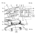
- FIGS. 3a to 3c another preferred embodiment of the present invention is shown.
- Fig. 1 are also explained in Fig. 3 a top view of the surface of the sheet with the device 10 according to the invention, a plan view of the inner surface of the sheet with the device 10 according to the invention and a cross-sectional schematic side view of the device according to the invention recognizable.
- an additional reinforcing element 4 is provided, which serves as a reinforcing element in the sheet 20 of the rail vehicle, to provide for a corresponding stabilization of the sheet of the rail vehicle.
- Figure 3c is still a schematic side view shown with the reinforcing element 5 and the inventive arrangement of the device.
- FIG. 4 the device 10 according to the invention is shown in an exploded view, wherein the inner contour frame 2b composed of four contests 2d, which have corresponding recesses 2c.
- the inner contour frame 2b composed of four contests 2d, which have corresponding recesses 2c.
- These corresponding recesses 2c make it possible, as already in the FIGS. 3a to 3c has been shown that the inner contour frame can be attached directly to a location on the inside of the sheet, where a reinforcing element 5 extends.
- the advantage of the individual contour parts 2d is that the inner contour frame can be adapted individually to the geometry of the inner panel or possibly occurring reinforcing elements 5.
- the four contour parts 2d each have a corresponding contour region K, which corresponds to the surface geometry of the inside of the metal sheet 20.
- the individual contour regions K of the individual contour parts 2d can have any desired shape.
- the outer contour frame 1 b has a contour region K ', which corresponds to the surface geometry of the outer side of the sheet 20.
- contour parts 2d have guides or depressions 2f in their edge regions, which provide a stable composition of the inner contour frame 2b.
Landscapes
- Engineering & Computer Science (AREA)
- Mechanical Engineering (AREA)
- Physics & Mathematics (AREA)
- Optics & Photonics (AREA)
- Vehicle Cleaning, Maintenance, Repair, Refitting, And Outriggers (AREA)
- Body Structure For Vehicles (AREA)
Applications Claiming Priority (1)
| Application Number | Priority Date | Filing Date | Title |
|---|---|---|---|
| DE102006055607A DE102006055607B3 (de) | 2006-11-24 | 2006-11-24 | Vorrichtung und Verfahren zur Reparatur bzw. zum Reparieren einer Außenhaut |
Publications (2)
| Publication Number | Publication Date |
|---|---|
| EP1925392A1 true EP1925392A1 (fr) | 2008-05-28 |
| EP1925392B1 EP1925392B1 (fr) | 2011-02-02 |
Family
ID=38988015
Family Applications (1)
| Application Number | Title | Priority Date | Filing Date |
|---|---|---|---|
| EP07022681A Not-in-force EP1925392B1 (fr) | 2006-11-24 | 2007-11-22 | Dispositif et procédé destinés à la réparation d'un revêtement |
Country Status (3)
| Country | Link |
|---|---|
| EP (1) | EP1925392B1 (fr) |
| DE (2) | DE102006055607B3 (fr) |
| ES (1) | ES2360733T3 (fr) |
Cited By (2)
| Publication number | Priority date | Publication date | Assignee | Title |
|---|---|---|---|---|
| CN114453612A (zh) * | 2021-12-29 | 2022-05-10 | 浙江博秦精密工业有限公司 | 一种用于手机配件高效加工的cnc设备及加工方法 |
| CN114833606A (zh) * | 2022-04-22 | 2022-08-02 | 大族激光科技产业集团股份有限公司 | 治具 |
Families Citing this family (1)
| Publication number | Priority date | Publication date | Assignee | Title |
|---|---|---|---|---|
| DE102024114402A1 (de) * | 2024-05-23 | 2025-11-27 | Dr. Ing. H.C. F. Porsche Aktiengesellschaft | Verfahren zum Reparieren einer Karosserie |
Citations (3)
| Publication number | Priority date | Publication date | Assignee | Title |
|---|---|---|---|---|
| JPS58174079A (ja) * | 1982-04-05 | 1983-10-13 | Mitsubishi Heavy Ind Ltd | 船殻構造材取替工法 |
| DE4034625A1 (de) * | 1990-10-31 | 1992-05-07 | Doege Eckart | Ziehverfahren |
| EP0970764A1 (fr) * | 1998-01-29 | 2000-01-12 | Amino Corporation | Appareil de formage de plaques sans matrice |
Family Cites Families (2)
| Publication number | Priority date | Publication date | Assignee | Title |
|---|---|---|---|---|
| US3338086A (en) * | 1965-03-29 | 1967-08-29 | Travis L Hunter | Multi-direction force clamp |
| DE20103876U1 (de) * | 2001-03-07 | 2002-07-11 | MV Marketing und Vertriebs-GmbH & Co. KG Wieländer + Schill, 78054 Villingen-Schwenningen | Vorrichtung zum Einschweißen von Blechen, insbesondere von Heckblechen |
-
2006
- 2006-11-24 DE DE102006055607A patent/DE102006055607B3/de not_active Expired - Fee Related
-
2007
- 2007-11-22 DE DE502007006415T patent/DE502007006415D1/de active Active
- 2007-11-22 EP EP07022681A patent/EP1925392B1/fr not_active Not-in-force
- 2007-11-22 ES ES07022681T patent/ES2360733T3/es active Active
Patent Citations (3)
| Publication number | Priority date | Publication date | Assignee | Title |
|---|---|---|---|---|
| JPS58174079A (ja) * | 1982-04-05 | 1983-10-13 | Mitsubishi Heavy Ind Ltd | 船殻構造材取替工法 |
| DE4034625A1 (de) * | 1990-10-31 | 1992-05-07 | Doege Eckart | Ziehverfahren |
| EP0970764A1 (fr) * | 1998-01-29 | 2000-01-12 | Amino Corporation | Appareil de formage de plaques sans matrice |
Cited By (2)
| Publication number | Priority date | Publication date | Assignee | Title |
|---|---|---|---|---|
| CN114453612A (zh) * | 2021-12-29 | 2022-05-10 | 浙江博秦精密工业有限公司 | 一种用于手机配件高效加工的cnc设备及加工方法 |
| CN114833606A (zh) * | 2022-04-22 | 2022-08-02 | 大族激光科技产业集团股份有限公司 | 治具 |
Also Published As
| Publication number | Publication date |
|---|---|
| EP1925392B1 (fr) | 2011-02-02 |
| ES2360733T3 (es) | 2011-06-08 |
| DE502007006415D1 (de) | 2011-03-17 |
| DE102006055607B3 (de) | 2008-05-15 |
Similar Documents
| Publication | Publication Date | Title |
|---|---|---|
| DE102007035483B4 (de) | Crasheinrichtung | |
| EP2197623B1 (fr) | Procédé de fabrication de machines | |
| WO2010023059A2 (fr) | Support pour composant structural d'aéronef pouvant être produit selon un procédé de fusion sélective par laser | |
| DE102008036824A1 (de) | Querträger für ein Kraftfahrzeug | |
| EP3077133B1 (fr) | Presse à cintrer | |
| EP0245635B1 (fr) | Dispositif de fixation pour panneaux | |
| DE102010035766A1 (de) | Verfahren und Befestigungsanordnung zum lagerichtigen Befestigen eines Geräts an einem Stukturteil eines Kraftfahrzeugs | |
| AT515153A1 (de) | Biegemaschine | |
| DE19802806A1 (de) | Trägerwerk zur Aufnahme von Funktionsaggregaten eines Kraftfahrzeugs | |
| EP1925392B1 (fr) | Dispositif et procédé destinés à la réparation d'un revêtement | |
| EP2578347A2 (fr) | Dispositif d'assemblage destiné à connecter des composants de structure d'un aéronef | |
| DE2638440B2 (de) | Ueberschlagschutzrahmen fuer kraftfahrzeuge | |
| DE102006055736A1 (de) | Querträger | |
| EP1931494B1 (fr) | Element d'assemblage | |
| EP2698295A2 (fr) | Tube télescopique réglable en longueur, béquille télescopique et procédé de montage | |
| WO2005056373A1 (fr) | Élément de carrosserie et procédé de production associé | |
| DE10029293B4 (de) | Vorrichtung und Verfahren zum Laserstrahlschweißen von Blechplatinen | |
| EP3693123B1 (fr) | Structure d'armature dotée d'une pluralité d'éléments profilés, et méthode de fabrication d'une structure d'armature dotée d'une pluralité d'éléments profilés | |
| DE10135158B4 (de) | Verfahren zur Montage von Schottplatten an Längsträgern eines Fahrzeugs, insbesondere eines Kraftfahrzeugs | |
| WO2004022416A1 (fr) | Composant hybride a elements de fixation en plastique moules par injection pour vehicules automobiles et procede de reparation dudit composant | |
| DE69517964T2 (de) | Rahmen | |
| DE102012214162A1 (de) | Multifunktionales Befestigungsprofil | |
| EP1363824B1 (fr) | Procede pour orienter une cabine de conducteur dans une position correcte et vehicule sur rails permettant de mettre en oeuvre ce procede | |
| DE102012221983B4 (de) | Konsole zur Verbindung von Dachaufbauten eines Schienenfahrzeugs mit dem Schienenfahrzeug | |
| DE10336589B3 (de) | Verfahren zur Reparatur von aus Profilteilen bestehenden Tragstrukturen, insbesondere Rahmenkonstruktionen von Kraftfahrzeug-Karosserien |
Legal Events
| Date | Code | Title | Description |
|---|---|---|---|
| PUAI | Public reference made under article 153(3) epc to a published international application that has entered the european phase |
Free format text: ORIGINAL CODE: 0009012 |
|
| AK | Designated contracting states |
Kind code of ref document: A1 Designated state(s): AT BE BG CH CY CZ DE DK EE ES FI FR GB GR HU IE IS IT LI LT LU LV MC MT NL PL PT RO SE SI SK TR |
|
| AX | Request for extension of the european patent |
Extension state: AL BA HR MK RS |
|
| 17P | Request for examination filed |
Effective date: 20080903 |
|
| 17Q | First examination report despatched |
Effective date: 20081001 |
|
| AKX | Designation fees paid |
Designated state(s): DE ES |
|
| GRAP | Despatch of communication of intention to grant a patent |
Free format text: ORIGINAL CODE: EPIDOSNIGR1 |
|
| GRAS | Grant fee paid |
Free format text: ORIGINAL CODE: EPIDOSNIGR3 |
|
| GRAA | (expected) grant |
Free format text: ORIGINAL CODE: 0009210 |
|
| AK | Designated contracting states |
Kind code of ref document: B1 Designated state(s): DE ES |
|
| REF | Corresponds to: |
Ref document number: 502007006415 Country of ref document: DE Date of ref document: 20110317 Kind code of ref document: P |
|
| REG | Reference to a national code |
Ref country code: DE Ref legal event code: R096 Ref document number: 502007006415 Country of ref document: DE Effective date: 20110317 |
|
| REG | Reference to a national code |
Ref country code: ES Ref legal event code: FG2A Ref document number: 2360733 Country of ref document: ES Kind code of ref document: T3 Effective date: 20110608 |
|
| PLBE | No opposition filed within time limit |
Free format text: ORIGINAL CODE: 0009261 |
|
| STAA | Information on the status of an ep patent application or granted ep patent |
Free format text: STATUS: NO OPPOSITION FILED WITHIN TIME LIMIT |
|
| 26N | No opposition filed |
Effective date: 20111103 |
|
| REG | Reference to a national code |
Ref country code: DE Ref legal event code: R097 Ref document number: 502007006415 Country of ref document: DE Effective date: 20111103 |
|
| PGFP | Annual fee paid to national office [announced via postgrant information from national office to epo] |
Ref country code: DE Payment date: 20131129 Year of fee payment: 7 |
|
| PGFP | Annual fee paid to national office [announced via postgrant information from national office to epo] |
Ref country code: ES Payment date: 20131120 Year of fee payment: 7 |
|
| REG | Reference to a national code |
Ref country code: DE Ref legal event code: R119 Ref document number: 502007006415 Country of ref document: DE |
|
| PG25 | Lapsed in a contracting state [announced via postgrant information from national office to epo] |
Ref country code: DE Free format text: LAPSE BECAUSE OF NON-PAYMENT OF DUE FEES Effective date: 20150602 |
|
| REG | Reference to a national code |
Ref country code: ES Ref legal event code: FD2A Effective date: 20160129 |
|
| PG25 | Lapsed in a contracting state [announced via postgrant information from national office to epo] |
Ref country code: ES Free format text: LAPSE BECAUSE OF NON-PAYMENT OF DUE FEES Effective date: 20141123 |