EP1925421A1 - Spritzgiessform mit Induktionsheizung, Spritzgiessverfahren, optischer Datenträger und Lichtleiterplatte - Google Patents
Spritzgiessform mit Induktionsheizung, Spritzgiessverfahren, optischer Datenträger und Lichtleiterplatte Download PDFInfo
- Publication number
- EP1925421A1 EP1925421A1 EP06124467A EP06124467A EP1925421A1 EP 1925421 A1 EP1925421 A1 EP 1925421A1 EP 06124467 A EP06124467 A EP 06124467A EP 06124467 A EP06124467 A EP 06124467A EP 1925421 A1 EP1925421 A1 EP 1925421A1
- Authority
- EP
- European Patent Office
- Prior art keywords
- injection
- moulding device
- mould
- top member
- carrier
- Prior art date
- Legal status (The legal status is an assumption and is not a legal conclusion. Google has not performed a legal analysis and makes no representation as to the accuracy of the status listed.)
- Granted
Links
- 238000001746 injection moulding Methods 0.000 title claims abstract description 36
- 238000010438 heat treatment Methods 0.000 title claims abstract description 27
- 230000001939 inductive effect Effects 0.000 title claims abstract description 7
- 230000003287 optical effect Effects 0.000 title claims description 3
- 238000004804 winding Methods 0.000 claims abstract description 18
- 230000005291 magnetic effect Effects 0.000 claims description 20
- 230000035699 permeability Effects 0.000 claims description 19
- 239000000463 material Substances 0.000 claims description 14
- 239000002826 coolant Substances 0.000 claims description 12
- 238000000034 method Methods 0.000 claims description 9
- 229910052581 Si3N4 Inorganic materials 0.000 claims description 8
- 229910010293 ceramic material Inorganic materials 0.000 claims description 8
- QYEXBYZXHDUPRC-UHFFFAOYSA-N B#[Ti]#B Chemical compound B#[Ti]#B QYEXBYZXHDUPRC-UHFFFAOYSA-N 0.000 claims description 6
- 229910052580 B4C Inorganic materials 0.000 claims description 6
- 229910033181 TiB2 Inorganic materials 0.000 claims description 6
- 239000007787 solid Substances 0.000 claims description 6
- HQVNEWCFYHHQES-UHFFFAOYSA-N silicon nitride Chemical compound N12[Si]34N5[Si]62N3[Si]51N64 HQVNEWCFYHHQES-UHFFFAOYSA-N 0.000 claims description 4
- PNEYBMLMFCGWSK-UHFFFAOYSA-N aluminium oxide Inorganic materials [O-2].[O-2].[O-2].[Al+3].[Al+3] PNEYBMLMFCGWSK-UHFFFAOYSA-N 0.000 claims description 3
- INAHAJYZKVIDIZ-UHFFFAOYSA-N boron carbide Chemical compound B12B3B4C32B41 INAHAJYZKVIDIZ-UHFFFAOYSA-N 0.000 claims description 3
- PMHQVHHXPFUNSP-UHFFFAOYSA-M copper(1+);methylsulfanylmethane;bromide Chemical compound Br[Cu].CSC PMHQVHHXPFUNSP-UHFFFAOYSA-M 0.000 claims description 3
- 229910052593 corundum Inorganic materials 0.000 claims description 3
- TWNQGVIAIRXVLR-UHFFFAOYSA-N oxo(oxoalumanyloxy)alumane Chemical compound O=[Al]O[Al]=O TWNQGVIAIRXVLR-UHFFFAOYSA-N 0.000 claims description 3
- 229910001845 yogo sapphire Inorganic materials 0.000 claims description 3
- 230000020169 heat generation Effects 0.000 abstract 1
- 239000010410 layer Substances 0.000 description 22
- 239000011347 resin Substances 0.000 description 16
- 229920005989 resin Polymers 0.000 description 16
- 238000001816 cooling Methods 0.000 description 7
- 230000005294 ferromagnetic effect Effects 0.000 description 6
- 238000002347 injection Methods 0.000 description 5
- 239000007924 injection Substances 0.000 description 5
- 238000004519 manufacturing process Methods 0.000 description 5
- RYGMFSIKBFXOCR-UHFFFAOYSA-N Copper Chemical compound [Cu] RYGMFSIKBFXOCR-UHFFFAOYSA-N 0.000 description 4
- PXHVJJICTQNCMI-UHFFFAOYSA-N Nickel Chemical compound [Ni] PXHVJJICTQNCMI-UHFFFAOYSA-N 0.000 description 4
- 239000010949 copper Substances 0.000 description 4
- 229910052802 copper Inorganic materials 0.000 description 4
- 239000003302 ferromagnetic material Substances 0.000 description 4
- 239000000969 carrier Substances 0.000 description 3
- 230000005672 electromagnetic field Effects 0.000 description 3
- 239000004698 Polyethylene Substances 0.000 description 2
- 239000004743 Polypropylene Substances 0.000 description 2
- 230000006835 compression Effects 0.000 description 2
- 238000007906 compression Methods 0.000 description 2
- 230000000694 effects Effects 0.000 description 2
- 239000011521 glass Substances 0.000 description 2
- 238000000465 moulding Methods 0.000 description 2
- 229910052759 nickel Inorganic materials 0.000 description 2
- 229920003229 poly(methyl methacrylate) Polymers 0.000 description 2
- -1 polyethylene Polymers 0.000 description 2
- 229920000573 polyethylene Polymers 0.000 description 2
- 239000004926 polymethyl methacrylate Substances 0.000 description 2
- 229920001155 polypropylene Polymers 0.000 description 2
- BSYNRYMUTXBXSQ-UHFFFAOYSA-N Aspirin Chemical compound CC(=O)OC1=CC=CC=C1C(O)=O BSYNRYMUTXBXSQ-UHFFFAOYSA-N 0.000 description 1
- ATUUNJCZCOMUKD-OKILXGFUSA-N MLI-2 Chemical compound C1[C@@H](C)O[C@@H](C)CN1C1=CC(C=2C3=CC(OC4(C)CC4)=CC=C3NN=2)=NC=N1 ATUUNJCZCOMUKD-OKILXGFUSA-N 0.000 description 1
- YXLXNENXOJSQEI-UHFFFAOYSA-L Oxine-copper Chemical compound [Cu+2].C1=CN=C2C([O-])=CC=CC2=C1.C1=CN=C2C([O-])=CC=CC2=C1 YXLXNENXOJSQEI-UHFFFAOYSA-L 0.000 description 1
- 229910000831 Steel Inorganic materials 0.000 description 1
- 239000002131 composite material Substances 0.000 description 1
- 239000004020 conductor Substances 0.000 description 1
- 230000001627 detrimental effect Effects 0.000 description 1
- 230000002500 effect on skin Effects 0.000 description 1
- 239000002245 particle Substances 0.000 description 1
- 239000004417 polycarbonate Substances 0.000 description 1
- 229920000515 polycarbonate Polymers 0.000 description 1
- 230000010076 replication Effects 0.000 description 1
- 230000003362 replicative effect Effects 0.000 description 1
- 238000007789 sealing Methods 0.000 description 1
- 239000002356 single layer Substances 0.000 description 1
- 239000010959 steel Substances 0.000 description 1
- 239000002344 surface layer Substances 0.000 description 1
- 239000012815 thermoplastic material Substances 0.000 description 1
- XLYOFNOQVPJJNP-UHFFFAOYSA-N water Substances O XLYOFNOQVPJJNP-UHFFFAOYSA-N 0.000 description 1
- 229910000859 α-Fe Inorganic materials 0.000 description 1
Images


Classifications
-
- B—PERFORMING OPERATIONS; TRANSPORTING
- B29—WORKING OF PLASTICS; WORKING OF SUBSTANCES IN A PLASTIC STATE IN GENERAL
- B29C—SHAPING OR JOINING OF PLASTICS; SHAPING OF MATERIAL IN A PLASTIC STATE, NOT OTHERWISE PROVIDED FOR; AFTER-TREATMENT OF THE SHAPED PRODUCTS, e.g. REPAIRING
- B29C45/00—Injection moulding, i.e. forcing the required volume of moulding material through a nozzle into a closed mould; Apparatus therefor
- B29C45/17—Component parts, details or accessories; Auxiliary operations
- B29C45/72—Heating or cooling
- B29C45/73—Heating or cooling of the mould
-
- B—PERFORMING OPERATIONS; TRANSPORTING
- B29—WORKING OF PLASTICS; WORKING OF SUBSTANCES IN A PLASTIC STATE IN GENERAL
- B29C—SHAPING OR JOINING OF PLASTICS; SHAPING OF MATERIAL IN A PLASTIC STATE, NOT OTHERWISE PROVIDED FOR; AFTER-TREATMENT OF THE SHAPED PRODUCTS, e.g. REPAIRING
- B29C45/00—Injection moulding, i.e. forcing the required volume of moulding material through a nozzle into a closed mould; Apparatus therefor
- B29C45/17—Component parts, details or accessories; Auxiliary operations
- B29C45/26—Moulds
- B29C45/263—Moulds with mould wall parts provided with fine grooves or impressions, e.g. for record discs
- B29C45/2642—Heating or cooling means therefor
-
- B—PERFORMING OPERATIONS; TRANSPORTING
- B29—WORKING OF PLASTICS; WORKING OF SUBSTANCES IN A PLASTIC STATE IN GENERAL
- B29C—SHAPING OR JOINING OF PLASTICS; SHAPING OF MATERIAL IN A PLASTIC STATE, NOT OTHERWISE PROVIDED FOR; AFTER-TREATMENT OF THE SHAPED PRODUCTS, e.g. REPAIRING
- B29C45/00—Injection moulding, i.e. forcing the required volume of moulding material through a nozzle into a closed mould; Apparatus therefor
- B29C45/17—Component parts, details or accessories; Auxiliary operations
- B29C45/72—Heating or cooling
- B29C45/73—Heating or cooling of the mould
- B29C2045/7368—Heating or cooling of the mould combining a heating or cooling fluid and non-fluid means
-
- B—PERFORMING OPERATIONS; TRANSPORTING
- B29—WORKING OF PLASTICS; WORKING OF SUBSTANCES IN A PLASTIC STATE IN GENERAL
- B29C—SHAPING OR JOINING OF PLASTICS; SHAPING OF MATERIAL IN A PLASTIC STATE, NOT OTHERWISE PROVIDED FOR; AFTER-TREATMENT OF THE SHAPED PRODUCTS, e.g. REPAIRING
- B29C45/00—Injection moulding, i.e. forcing the required volume of moulding material through a nozzle into a closed mould; Apparatus therefor
- B29C45/17—Component parts, details or accessories; Auxiliary operations
- B29C45/72—Heating or cooling
- B29C45/73—Heating or cooling of the mould
- B29C2045/7393—Heating or cooling of the mould alternately heating and cooling
-
- Y—GENERAL TAGGING OF NEW TECHNOLOGICAL DEVELOPMENTS; GENERAL TAGGING OF CROSS-SECTIONAL TECHNOLOGIES SPANNING OVER SEVERAL SECTIONS OF THE IPC; TECHNICAL SUBJECTS COVERED BY FORMER USPC CROSS-REFERENCE ART COLLECTIONS [XRACs] AND DIGESTS
- Y10—TECHNICAL SUBJECTS COVERED BY FORMER USPC
- Y10T—TECHNICAL SUBJECTS COVERED BY FORMER US CLASSIFICATION
- Y10T156/00—Adhesive bonding and miscellaneous chemical manufacture
- Y10T156/10—Methods of surface bonding and/or assembly therefor
- Y10T156/1002—Methods of surface bonding and/or assembly therefor with permanent bending or reshaping or surface deformation of self sustaining lamina
- Y10T156/1039—Surface deformation only of sandwich or lamina [e.g., embossed panels]
- Y10T156/1041—Subsequent to lamination
Definitions
- the present invention relates to an injection-moulding device, comprising at least first and second mould parts, defining a mould cavity, wherein at least one of the mould parts comprises heating means, for heating the mould part in the vicinity of a mould cavity surface, said heating means comprising an inductive coil having a plurality of windings and being powered by an oscillator.
- Such an injection-moulding device is disclosed e.g. in US, 4,563,145 .
- This document describes a moulding block for manufacturing flat information carriers from thermoplastic material.
- the moulding block comprises a glass plate, wherein a copper pipe is embedded.
- the copper pipe can be used both as a cooling channel and an inductive coil.
- On top of the glass plate a ferromagnetic material layer is placed, which absorbs some of the energy emitted from the coil.
- a copper layer is placed, having high thermal conductivity. The copper layer conducts the generated heat to a surface layer in the mould part.
- This device may thus be used both to actively heat and cool the mould, which provides for shorter process cycles and/or improved process yield.
- An improved and more efficient heating functionality is however needed to further improve an injection moulding process.
- An object of the present invention is therefore to provide an injection moulding device with improved active heating capability. This object is achieved by means of an injection moulding device as defined in claim 1.
- the injection moulding device comprises at least first and second mould parts, defining a mould cavity, wherein at least one of the mould parts comprises heating means, for heating the mould part in the vicinity of a mould cavity surface, said heating means comprising an inductive coil having a plurality of windings and being powered by an oscillator.
- the mould part comprises a top member, at the mould cavity surface, a carrier member, placed beneath the top member as seen from the cavity surface and comprising grooves for accommodating said coil windings, and an intermediate member placed between the top member and the carrier member, wherein the top member has a resistivity lower than 1.5*10 -6 ⁇ m, the carrier member has a relative magnetic permeability higher than 50, and a resistivity higher than 20*10 -6 ⁇ m, and the intermediate member has a resistivity higher than 20*10 -6 ⁇ m and a relative magnetic permeability lower than 1.2.
- the top member can be made very thin, since the intermediate member can provide the necessary rigidity while not functioning as a susceptor for electromagnetic energy to any greater extent. As the top member can be made thin, the development of heat may be concentrated to a region close to the mould cavity surface, thus providing efficient heating. Additionally, the top member may be provided in a ferromagnetic material.
- the grooves in the carrier member may be arranged to convey a coolant.
- the thermal conductivity of the intermediate member may then be higher than 10 W/mK, thus very efficiently transporting heat from the mould cavity surface when the mould is to be cooled.
- the intermediate member may comprise a ceramic material, such as Aluminum Nitride, A1N, Boron Carbide, B 4 C, Silicon Nitride, Si 3 N 4 , Titanium Diboride, TiB 2 , or Aluminum Oxide, Al 2 O 3 .
- a ceramic material such as Aluminum Nitride, A1N, Boron Carbide, B 4 C, Silicon Nitride, Si 3 N 4 , Titanium Diboride, TiB 2 , or Aluminum Oxide, Al 2 O 3 .
- a backing member may be placed behind the carrier member as seen from the cavity surface and the coil may have return windings that are placed between the carrier member and the backing member.
- the top member may then have a resistivity higher than 0.05*10 -6 ⁇ m (i.e. in the interval 0.05*10 -6 - 1.5*10 -6 ⁇ m), and the backing member may have a resistivity lower than 0.05*10 -6 ⁇ m.
- the elasticity modulus of the intermediate member may be 200 GPa or higher.
- the relative magnetic permeability of the top member may be higher than 1.2, as the top member can be made thin.
- the top member may be solid or laminated.
- an upper top member layer may comprise a material with a relative magnetic permeability higher than 1.2 and a lower top member layer may comprise a material with a relative magnetic permeability lower than 1.2.
- the intermediate member may comprise grooves facing the grooves of the carrier member.
- a method for injection moulding may use an injection-moulding device as defined above and may be used to produce e.g. optical information carriers and lightguide plates.
- Figs 1-4 describe schematically steps in an injection-molding process utilizing an injection moulding device. More particularly, an injection compression cycle is schematically illustrated.
- a first mould part 1 is fixed and comprises a resin injecting nozzle 2, which is fed by an extruder. Together with a second, moveable mould part 3 and a sub-part 8 on the second moveable part 3, the first mould part forms a cavity 4.
- the first and second mould parts further include means, in the form of coolant ducts 5, for cooling the mould parts in the vicinity of the cavity 4.
- the first and second mould parts 1, 3 include means, in the form of inductor coils 6, for heating the mould parts in the vicinity of the cavity 4.
- the heating means 6 are activated so as to heat the mould parts 1, 3 while hot resin is injected into the cavity 4.
- the first and second mould parts are separated, but the cavity 4 is closed by means of the sub-part 8 on the second mould part 3.
- An amount of resin, suitable for finally filling the cavity, is injected between the mould parts 1, 3.
- the sub-part 8 can slide to some extent in the axial direction in relation to the second mould part 3, and may be provided as a ring surrounding the cavity and defining the periphery of the same, such that the resin does not escape through the gap between the mould parts. Air may still escape through a small gap between one of the mould parts and the sub-part as the resin is injected. This gap may be e.g. 10 ⁇ m wide.
- the injection phase has been completed, and a clamping force is applied to the second, moveable mould part 3 in order to press the second part 3 towards the first mould part 1.
- This serves to make the resin fill the cavity entirely and to replicate any surface structure e.g. on the second mould part 3 on the corresponding surface of the injected resin.
- the injected resin takes up the greater part of the applied force, thanks to the moveable sub-part 8.
- the second mould part moves slightly towards the first mould part also after the cavity is completely filled, to compensate for the shrinking of the resin as the resin gets cooler.
- the heating of the mould may be switched off before or during this phase of the cycle.
- the above described cycle may be called “injection compression” and is useful e.g. for the purpose of replicating fine surface structures on a finished product.
- the invention to be described would however also be useful for so-called “straight injection” cycles, where the mould parts are in a fully closed state, with applied clamping force, as the resin is injected, and no particular clamping step is used. No sub-part (8 as in figs 1-4) is thus needed, and the cavity may be defined entirely by the forms of a first and second mould part. The shrinking may then be compensated for by means of resin injected by the extruder to which the nozzle is connected.
- active heating of the mould part/s takes place.
- active heating allows shorter cycle times and the production of thinner structures with greater surfaces.
- cooling channels may be placed closer to the cavity surface or thermally quicker materials may be used, both in terms of thermal conduction and specific heat, close to the cavity surface. Lower clamping forces may be used with maintained replication performance.
- Fig 5 shows a cross section of a mould part at a cavity surface.
- the term “top” generally refers to parts closer to the mould cavity than the term “bottom”, irrespective of the actual orientation of the injection moulding device.
- This mould part has been designed to achieve a development of thermal energy which is to a great extent concentrated to an area close to the cavity surface 20.
- the mould part has a top member 22, an intermediate member 24, a carrier member 26, comprising a coil 30, and a backing member 28.
- the top member 22 functions as a susceptor for an oscillating electromagnetic field generated by the coil 30, i.e. develops thermal energy when exposed to the field.
- the top member 22 may be solid or laminated.
- thermal energy raises the temperature of top member as the electromagnetic field is generated. To some extent, this effect may be due to magnetic hysteresis in the top member 22 material, but in most cases, induced eddy currents provide the greater part of the developed thermal energy.
- the top member may in these cases be thin, less than about 1 mm thick. If e.g. a 1 cm top member would be used in order to provide a very stiff structure, a great part of the thermal energy would be developed from eddy currents close to the bottom surface of the top member, at a distance from the mould cavity surface. Even if some of this energy would be conveyed to the top surface during the heating part of the cycle, the efficiency of such an arrangement may be too low. Thanks to the use of an intermediate member, as will be described below, it is however possible to use a thin top member structure.
- the top member 22 should comprise an electrically conductive material with a resistivity at least lower than 1.5*10 -6 ⁇ m.
- the top member may be chosen freely. In general, a high relative permeability will have the effect that the eddy currents to a greater extent are induced close to the bottom surface of the top part. This may as mentioned be detrimental for the efficiency if the top member is very thick.
- a thin ferromagnetic top member may be used as this entails a high and rapid thermal power development at the mould cavity surface.
- Suitable top member materials include ferrite and austenitic type steels (e.g. STAVAX ESR or GRIPER, sold by Uddeholm Tooling AB of Hagfors, Sweden), or other electrically conductive ferromagnetic or non-ferromagnetic materials such as e.g. Nickel.
- ferrite and austenitic type steels e.g. STAVAX ESR or GRIPER, sold by Uddeholm Tooling AB of Hagfors, Sweden
- other electrically conductive ferromagnetic or non-ferromagnetic materials such as e.g. Nickel.
- the carrier member 26 comprises grooves 32 that are open towards the cavity surface and contain coil winding turns.
- the carrier member material has a high relative magnetic permeability, at least 50 at the relevant temperatures, in order to efficiently form a part of a magnetic circuit around each winding turn.
- the open grooves serve not to short-circuit these magnetic circuits.
- relevant temperatures is here meant temperatures occurring in the relative section of the mould part during the process cycle.
- the windings may comprise litz wires.
- the carrier part should at the same time have a high resistivity, at least higher than 20*10 -6 ⁇ m. This serves to avoid that thermal energy is developed in the carrier part 26 to any greater extent, instead focusing the temperature increase at the mold cavity surface.
- a suitable material is Permedyn TM MF1, which is a soft magnetic composite, including ferromagnetic, electrically insulated particles. Wall parts between adjacent grooves 32 in the carrier member may be dimensioned under consideration of the saturation level of the used material.
- the grooves 32 may at the same time be used to convey a coolant, such as water, which is used to cool the mold part during a part of the production cycle.
- a coolant such as water
- the coil windings may then be placed at the far end of the grooves, as seen from the cavity surface, in order provide a coolant flow closer to the top member 22.
- the intermediate member 24 is used to provide a mechanical stiffness which allows the top part 22 to be thin. At the same time, the intermediate member should not to any greater extent itself function as a susceptor, thereby concentrating the heating to the top member 22 when the electromagnetic field is applied. Thus, materials with high resistivity, low relative magnetic permeability and high elasticity modulus are preferred.
- the resistivity may be higher than 20*10 -6 ⁇ m and the relative magnetic permeability lower than 1.2.
- the required elasticity modulus depends on the thickness of the intermediate layer as well as the mechanical stresses to which the top member 22 and the intermediate member 24 are exposed, and on other geometric properties, such as the width of the grooves in the carrier member. It has been found that an elasticity modulus of about 200 GPa is sufficient in most cases. As illustrated in fig 5, grooves 31 may also be provided in the intermediate member 24, facing the grooves 32 of the carrier member 26. Greater overall cooling ducts may thus be achieved, or alternatively the groove depth in the carrier member may be reduced with maintained cross-section.
- a clamping pressure as high as 45 MPa may in conventional injection moulding devices be applied on the injected resin by the mold parts.
- the active heating/cooling allows the clamping pressure to be substantially reduced.
- the bearing distance over a carrier member groove is typically only about 2.5 mm.
- the pressure of that coolant is applied on the other side of the intermediate member 24, and this pressure may be applied over a greater bearing distance, greater than the radius of the mould surface as illustrated by the carrier member in fig 6. Therefore, the coolant pressure may in many cases determine the required stiffness of the intermediate member 24.
- an intermediate member with good thermal conductivity provides improved cooling of the top member during the phase when the mold is cooled. Further, the intermediate member may be capable of sealing the grooves too enclose the coolant in a groove, even if some leakage of coolant between adjacent grooves may be allowed.
- ceramic materials such as Aluminum Nitride, AIN, Boron Carbide, B 4 C, Silicon Nitride ,Si 3 N 4 , or Titanium Diboride, TiB 2 , may be used. Sintered Aluminum Oxide, Al 2 O 3 , may also be considered. Generally, a thermal conductivity higher than 10 W/mK in the intermediate is preferred.
- the backing member 28 is situated behind the carrier member 26 as seen from the mould cavity surface. As will be illustrated later, return winding parts of the coil windings 30 are placed between the carrier member 26 and the backing member 28, and therefore the backing member 28 may preferably be made in a material that avoids excessive development of thermal energy due to the return windings.
- the backing member may therefore have a low resistivity (e.g. ⁇ 0.03*10 -6 ⁇ m), preferably lower than the top member resistivity. A low relative magnetic permeability ( ⁇ 1.2) is further preferred.
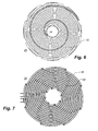
- Fig 6 shows a front view of a circular carrier member
- fig 7 illustrates exposed a winding as wound in the carrier member of fig 6.
- the coil 30 is wound in eight turns around the carrier member 26, which has a central opening 34.
- the upper part of each turn 36 as seen from the mould cavity, extends in a groove 32, formed as an Archimedean spiral, from the periphery of the carrier member to the central opening 34.
- the bottom part 38 of each turn extends in a comparatively short path, between the carrier member and the backing member, from the central opening to the periphery of the carrier member.
- the backing member 28 and the top member 22 may be in galvanic contact, electrically connected at the central opening 34 and at the periphery of the carrier member 26. This closes the eddy current loops in the radial direction and avoids any risk of the build-up of excessive voltages at these locations due to the applied oscillating field.
- Fig 8 shows a cross section through a laminated top member.
- the top member comprises an upper layer 40 and a lower layer 42.
- the upper layer may typically comprise a stamper, that is used to generate a surface pattern on the injected resin. If the lower layer functions as a susceptor, the upper layer may be chosen also in a material that does not exhibit good susceptor properties. The upper layer may be replaced, e.g. when a new pattern should be printed.
- the upper top member layer functions as a sort of low-pass filter, equalizing the temperature both over time and over the cavity surface. This may be used to avoid excessive temperature variations at the cavity surface that may be caused by e.g. the spacing between the coil turns.
- a laminated top member may therefore be useful even in cases where separate stampers are not used.
- One useful configuration is to have a ferromagnetic upper layer (relative magnetic permeability higher than 1.2) and a non-ferromagnetic lower top member layer (relative magnetic permeability lower than 1.2).
- Three or more layers in the top member may also be considered.
- Fig 9 shows a cross section through a solid top member 22', comprising a single layer 44.
- a top member may of course be less complex to manufacture. It has been considered to use a solid top member with an integrated stamper.
- Such a top member may be made in a ferromagnetic material, e.g. in nickel.
- the mould part may thus have the following exemplary configuration having eight winding turns and being powered by a 40 kHz impulse: Part Operating temperature Material Dimensions Top member, 1 st layer (stamper) 20-350 °C Nickel 0.3 mm thick Top member, 2 nd layer 20-350 °C Griper 0.5 mm thick Intermediate member 20-350 °C Silicon Nitride, Si 3 N 4 4 mm thick Carrier member 20-170 °C MF1 16 mm thick; 2.5 mm wide and 6.25 mm deep grooves at c-c distance 6 mm Backing member 20-170 °C Copper 8 mm thick
- the described injection-moulding device may be useful for producing a variety of different products. Apart from information carriers such as CDs and DVDs and sub-layers of such items, e.g. lightguide plates may be produced.
- the mould cavity surfaces may have different shapes. As an example, fig 10 illustrates a rectangular carrier member.
- Typical resins to be used in an injection moulding device include e.g. polymethyl methacrylate (PMMA), polycarbonate (PC), polyethylene (PE), and polypropylene (PP) .
- PMMA polymethyl methacrylate
- PC polycarbonate
- PE polyethylene
- PP polypropylene
Landscapes
- Engineering & Computer Science (AREA)
- Manufacturing & Machinery (AREA)
- Mechanical Engineering (AREA)
- Moulds For Moulding Plastics Or The Like (AREA)
- Injection Moulding Of Plastics Or The Like (AREA)
Priority Applications (4)
| Application Number | Priority Date | Filing Date | Title |
|---|---|---|---|
| AT06124467T ATE508854T1 (de) | 2006-11-21 | 2006-11-21 | Spritzgiessform mit induktionsheizung sowie spritzgiessverfahren |
| EP06124467A EP1925421B1 (de) | 2006-11-21 | 2006-11-21 | Spritzgiessform mit Induktionsheizung sowie Spritzgiessverfahren |
| PCT/EP2007/009978 WO2008061683A1 (en) | 2006-11-21 | 2007-11-19 | Injection-mould with inductive heating, injection moulding method, optical information carrier and light guide plate |
| US12/469,341 US8235697B2 (en) | 2006-11-21 | 2009-05-20 | Injection mold with inductive heating |
Applications Claiming Priority (1)
| Application Number | Priority Date | Filing Date | Title |
|---|---|---|---|
| EP06124467A EP1925421B1 (de) | 2006-11-21 | 2006-11-21 | Spritzgiessform mit Induktionsheizung sowie Spritzgiessverfahren |
Publications (2)
| Publication Number | Publication Date |
|---|---|
| EP1925421A1 true EP1925421A1 (de) | 2008-05-28 |
| EP1925421B1 EP1925421B1 (de) | 2011-05-11 |
Family
ID=37946311
Family Applications (1)
| Application Number | Title | Priority Date | Filing Date |
|---|---|---|---|
| EP06124467A Not-in-force EP1925421B1 (de) | 2006-11-21 | 2006-11-21 | Spritzgiessform mit Induktionsheizung sowie Spritzgiessverfahren |
Country Status (4)
| Country | Link |
|---|---|
| US (1) | US8235697B2 (de) |
| EP (1) | EP1925421B1 (de) |
| AT (1) | ATE508854T1 (de) |
| WO (1) | WO2008061683A1 (de) |
Cited By (6)
| Publication number | Priority date | Publication date | Assignee | Title |
|---|---|---|---|---|
| EP2260993A1 (de) | 2009-06-12 | 2010-12-15 | Robert Bosch GmbH | Spritzgusswerkzeug |
| EP2434836A3 (de) * | 2010-09-27 | 2012-12-19 | Chung Yuan Christian University | Induktionswärmevorrichtung und Steuerungsverfahren dafür |
| CN102950782A (zh) * | 2011-08-09 | 2013-03-06 | 通用汽车环球科技运作有限责任公司 | 向感应加热工具表面施加可变磁性质以及利用该工具来制造部件的方法 |
| CN106457617A (zh) * | 2014-06-27 | 2017-02-22 | 沙特基础工业全球技术有限公司 | 具有多材料核芯的感应加热的模具装置及其使用方法 |
| US9962861B2 (en) | 2011-06-28 | 2018-05-08 | Tctech Sweden Ab | Device and method for heating a mould or tool |
| US10035286B2 (en) | 2012-12-27 | 2018-07-31 | Tctech Sweden Ab | Device and method for heating a mould or tool |
Families Citing this family (17)
| Publication number | Priority date | Publication date | Assignee | Title |
|---|---|---|---|---|
| EP1800829A1 (de) * | 2005-12-22 | 2007-06-27 | Thermal Cyclic Technologies TCTech i Stockholm AB | Spritzgiesswerkzeug mit Induktionsheizung und Spritzgiessverfahren mit einem Induktionsheizschritt. |
| EP2910358B1 (de) | 2010-07-16 | 2018-12-05 | SiO2 Medical Products, Inc. | Spritzenanordnung |
| DE102011053867B4 (de) * | 2011-09-22 | 2015-08-06 | Dr. Schneider Kunststoffwerke Gmbh | Spritzgießwerkzeug mit Induktor für die Herstellung von Kunststoffformteilen |
| RU2014133966A (ru) | 2012-02-24 | 2016-03-20 | Дзе Проктер Энд Гэмбл Компани | Пресс-форма для инжекционного формования с упрощённой системой охлаждения |
| US20130295219A1 (en) * | 2012-05-02 | 2013-11-07 | Ralph Edwin Neufarth | Injection Mold Having a Simplified Evaporative Cooling System or a Simplified Cooling System with Exotic Cooling Fluids |
| US8770968B2 (en) * | 2012-04-13 | 2014-07-08 | GM Global Technology Operations LLC | Injection molding tool with embedded induction heater |
| CA2875235C (fr) * | 2012-06-19 | 2021-06-22 | Roctool | Moule a chauffage et refroidissement rapides |
| EP2922680A2 (de) | 2012-11-21 | 2015-09-30 | iMFLUX Inc. | Verkleinerter läufer für ein spritzgiessformsystem |
| AT514610B1 (de) | 2013-06-21 | 2015-02-15 | Engel Austria Gmbh | Mischkopf mit auf Mischkammer gerichteten Wellenemitter |
| US10085584B2 (en) * | 2014-06-09 | 2018-10-02 | Whirlpool Corporation | Method of regulating temperature for sous vide cooking and apparatus therefor |
| DE102015114880A1 (de) * | 2015-09-04 | 2017-03-09 | Diehl Aircabin Gmbh | Induktiv beheizbares Formwerkzeug |
| ITUB20159600A1 (it) * | 2015-12-28 | 2017-06-28 | Velatech S R L | Pressa a termo induzione per la saldatura di circuiti stampati e metodo attuato da tale pressa |
| CN114555310B (zh) * | 2019-07-22 | 2025-10-28 | 铸造实验室有限公司 | 铸造模具 |
| EP3842208B1 (de) * | 2019-12-23 | 2023-09-20 | COBES GmbH | Verwendung einer vorrichtung zur induktiven erwärmung eines elektrisch-leitenden, vorzugsweise metallischen, einlegeteils als bestandteil eines spritzgiesslings |
| US11752684B2 (en) | 2020-11-28 | 2023-09-12 | Blockwise Engineering Llc | Inductively heated mold system |
| US12318967B2 (en) | 2020-11-28 | 2025-06-03 | Blockwise Engineering Llc | Inductively heated mold system |
| DE102021117463B4 (de) | 2021-07-06 | 2025-05-08 | 3D Laserdruck GmbH & Co. KG | Druck- oder spritzgusswerkzeug |
Citations (4)
| Publication number | Priority date | Publication date | Assignee | Title |
|---|---|---|---|---|
| US4563145A (en) | 1983-12-22 | 1986-01-07 | U.S. Philips Corporation | Alternately heatable and coolable moulding block |
| JPH068250A (ja) * | 1992-06-26 | 1994-01-18 | Toshiba Emi Ltd | 光ディスク成形金型 |
| US20040188427A1 (en) | 2003-03-24 | 2004-09-30 | Jung-Tang Huang | High frequency induction heater built in an injection mold |
| JP2005335234A (ja) * | 2004-05-27 | 2005-12-08 | Fuiisa Kk | 射出成形法及び射出成形装置 |
Family Cites Families (6)
| Publication number | Priority date | Publication date | Assignee | Title |
|---|---|---|---|---|
| JP2002226954A (ja) * | 2000-11-30 | 2002-08-14 | Nisshin Steel Co Ltd | Fe−Cr系軟磁性材料及び製造方法 |
| WO2003079728A1 (en) * | 2002-03-19 | 2003-09-25 | Matsushita Electric Industrial Co., Ltd. | Induction heating device |
| JP4809039B2 (ja) * | 2005-11-07 | 2011-11-02 | 偕成エンジニア株式会社 | 電磁誘導型検査装置および電磁誘導型検査方法 |
| EP1800829A1 (de) * | 2005-12-22 | 2007-06-27 | Thermal Cyclic Technologies TCTech i Stockholm AB | Spritzgiesswerkzeug mit Induktionsheizung und Spritzgiessverfahren mit einem Induktionsheizschritt. |
| US7386243B2 (en) * | 2006-03-07 | 2008-06-10 | Kabushiki Kaisha Toshiba | Heating apparatus and induction heating control method |
| US20100000980A1 (en) * | 2008-07-02 | 2010-01-07 | Bogdan Popescu | Induction Heating System with Versatile Inductive Cartridge |
-
2006
- 2006-11-21 EP EP06124467A patent/EP1925421B1/de not_active Not-in-force
- 2006-11-21 AT AT06124467T patent/ATE508854T1/de not_active IP Right Cessation
-
2007
- 2007-11-19 WO PCT/EP2007/009978 patent/WO2008061683A1/en not_active Ceased
-
2009
- 2009-05-20 US US12/469,341 patent/US8235697B2/en not_active Expired - Fee Related
Patent Citations (4)
| Publication number | Priority date | Publication date | Assignee | Title |
|---|---|---|---|---|
| US4563145A (en) | 1983-12-22 | 1986-01-07 | U.S. Philips Corporation | Alternately heatable and coolable moulding block |
| JPH068250A (ja) * | 1992-06-26 | 1994-01-18 | Toshiba Emi Ltd | 光ディスク成形金型 |
| US20040188427A1 (en) | 2003-03-24 | 2004-09-30 | Jung-Tang Huang | High frequency induction heater built in an injection mold |
| JP2005335234A (ja) * | 2004-05-27 | 2005-12-08 | Fuiisa Kk | 射出成形法及び射出成形装置 |
Cited By (10)
| Publication number | Priority date | Publication date | Assignee | Title |
|---|---|---|---|---|
| EP2260993A1 (de) | 2009-06-12 | 2010-12-15 | Robert Bosch GmbH | Spritzgusswerkzeug |
| DE102009026916A1 (de) | 2009-06-12 | 2010-12-16 | Robert Bosch Gmbh | Spritzgusswerkzeug |
| EP2434836A3 (de) * | 2010-09-27 | 2012-12-19 | Chung Yuan Christian University | Induktionswärmevorrichtung und Steuerungsverfahren dafür |
| US9962861B2 (en) | 2011-06-28 | 2018-05-08 | Tctech Sweden Ab | Device and method for heating a mould or tool |
| CN102950782A (zh) * | 2011-08-09 | 2013-03-06 | 通用汽车环球科技运作有限责任公司 | 向感应加热工具表面施加可变磁性质以及利用该工具来制造部件的方法 |
| US9095994B2 (en) | 2011-08-09 | 2015-08-04 | GM Global Technology Operations LLC | Method for applying variable magnetic properties to a induction heated tool face and manufacturing parts using the tool |
| CN102950782B (zh) * | 2011-08-09 | 2018-07-10 | 通用汽车环球科技运作有限责任公司 | 向感应加热工具表面施加可变磁性质以及利用该工具来制造部件的方法 |
| US10035286B2 (en) | 2012-12-27 | 2018-07-31 | Tctech Sweden Ab | Device and method for heating a mould or tool |
| CN106457617A (zh) * | 2014-06-27 | 2017-02-22 | 沙特基础工业全球技术有限公司 | 具有多材料核芯的感应加热的模具装置及其使用方法 |
| US10427329B2 (en) | 2014-06-27 | 2019-10-01 | Sabic Global Technologies B.V. | Induction heated mold apparatus with multimaterial core and method of using the same |
Also Published As
| Publication number | Publication date |
|---|---|
| EP1925421B1 (de) | 2011-05-11 |
| US8235697B2 (en) | 2012-08-07 |
| ATE508854T1 (de) | 2011-05-15 |
| US20090239023A1 (en) | 2009-09-24 |
| WO2008061683A1 (en) | 2008-05-29 |
Similar Documents
| Publication | Publication Date | Title |
|---|---|---|
| US8235697B2 (en) | Injection mold with inductive heating | |
| Yao et al. | Rapid thermal cycling of injection molds: An overview on technical approaches and applications | |
| US7118372B2 (en) | Molding tool having a heating and cooling medium | |
| CN101678570B (zh) | 用于聚合物成型的模塑设备和方法 | |
| KR101197703B1 (ko) | 물건 제조용 재료 가열방법 및 그 장치 | |
| US9096009B2 (en) | Method for forming a polymer part | |
| JP7403011B2 (ja) | 熱可塑性部分を有する部品のための誘導加熱成形 | |
| US20040041303A1 (en) | Method and apparatus for rapid mold heating and cooling | |
| US7981350B2 (en) | Method and apparatus for injection molding having an inductive coil heater | |
| US8926887B2 (en) | Device for shaping materials using induction heating that enables preheating of the device | |
| US20180117806A1 (en) | Resin injection apparatus and method of manufacturing core product | |
| EP1800828B1 (de) | Spritzgiesswerkzeug mit Induktionsheizung und Spritzgiessverfahren mit einem Induktionsheizschritt | |
| JP4218989B2 (ja) | 樹脂成形用金型 | |
| CN101352901A (zh) | 模具 | |
| WO2007073290A1 (en) | Moulding device and method | |
| EP1800822A1 (de) | Spritzgiesswerkzeug mit spiralförmigen Kühlkanälen und entsprechendes Spritzgiessverfahren | |
| JP2010094867A (ja) | 円筒状成形品の射出成形用金型、射出成形方法及び成形品 | |
| JP2015112749A (ja) | 射出成形用金型 | |
| JP2017047544A (ja) | インモールド成形体の製造方法 |
Legal Events
| Date | Code | Title | Description |
|---|---|---|---|
| PUAI | Public reference made under article 153(3) epc to a published international application that has entered the european phase |
Free format text: ORIGINAL CODE: 0009012 |
|
| AK | Designated contracting states |
Kind code of ref document: A1 Designated state(s): AT BE BG CH CY CZ DE DK EE ES FI FR GB GR HU IE IS IT LI LT LU LV MC NL PL PT RO SE SI SK TR |
|
| AX | Request for extension of the european patent |
Extension state: AL BA HR MK RS |
|
| 17P | Request for examination filed |
Effective date: 20081124 |
|
| AKX | Designation fees paid |
Designated state(s): AT BE BG CH CY CZ DE DK EE ES FI FR GB GR HU IE IS IT LI LT LU LV MC NL PL PT RO SE SI SK TR |
|
| 17Q | First examination report despatched |
Effective date: 20090112 |
|
| RTI1 | Title (correction) |
Free format text: INJECTION-MOULD WITH INDUCTIVE HEATING AND INJECTION MOULDING METHOD |
|
| GRAP | Despatch of communication of intention to grant a patent |
Free format text: ORIGINAL CODE: EPIDOSNIGR1 |
|
| GRAS | Grant fee paid |
Free format text: ORIGINAL CODE: EPIDOSNIGR3 |
|
| GRAA | (expected) grant |
Free format text: ORIGINAL CODE: 0009210 |
|
| AK | Designated contracting states |
Kind code of ref document: B1 Designated state(s): AT BE BG CH CY CZ DE DK EE ES FI FR GB GR HU IE IS IT LI LT LU LV MC NL PL PT RO SE SI SK TR |
|
| REG | Reference to a national code |
Ref country code: GB Ref legal event code: FG4D |
|
| REG | Reference to a national code |
Ref country code: CH Ref legal event code: EP |
|
| REG | Reference to a national code |
Ref country code: IE Ref legal event code: FG4D |
|
| REG | Reference to a national code |
Ref country code: DE Ref legal event code: R096 Ref document number: 602006021921 Country of ref document: DE Effective date: 20110622 |
|
| RAP2 | Party data changed (patent owner data changed or rights of a patent transferred) |
Owner name: AVALON INNOVATION AB |
|
| REG | Reference to a national code |
Ref country code: NL Ref legal event code: VDEP Effective date: 20110511 |
|
| REG | Reference to a national code |
Ref country code: DE Ref legal event code: R081 Ref document number: 602006021921 Country of ref document: DE Owner name: AVALON INNOVATION AB, SE Free format text: FORMER OWNER: THERMAL CYCLIC TECHNOLOGIES TCTECH I STOCKHOLM AB, SPANGA, SE Effective date: 20110826 Ref country code: DE Ref legal event code: R081 Ref document number: 602006021921 Country of ref document: DE Owner name: TCTECH SWEDEN AB, SE Free format text: FORMER OWNER: THERMAL CYCLIC TECHNOLOGIES TCTECH I STOCKHOLM AB, SPANGA, SE Effective date: 20110826 |
|
| PG25 | Lapsed in a contracting state [announced via postgrant information from national office to epo] |
Ref country code: PT Free format text: LAPSE BECAUSE OF FAILURE TO SUBMIT A TRANSLATION OF THE DESCRIPTION OR TO PAY THE FEE WITHIN THE PRESCRIBED TIME-LIMIT Effective date: 20110912 Ref country code: LT Free format text: LAPSE BECAUSE OF FAILURE TO SUBMIT A TRANSLATION OF THE DESCRIPTION OR TO PAY THE FEE WITHIN THE PRESCRIBED TIME-LIMIT Effective date: 20110511 Ref country code: SE Free format text: LAPSE BECAUSE OF FAILURE TO SUBMIT A TRANSLATION OF THE DESCRIPTION OR TO PAY THE FEE WITHIN THE PRESCRIBED TIME-LIMIT Effective date: 20110511 |
|
| PG25 | Lapsed in a contracting state [announced via postgrant information from national office to epo] |
Ref country code: LV Free format text: LAPSE BECAUSE OF FAILURE TO SUBMIT A TRANSLATION OF THE DESCRIPTION OR TO PAY THE FEE WITHIN THE PRESCRIBED TIME-LIMIT Effective date: 20110511 Ref country code: GR Free format text: LAPSE BECAUSE OF FAILURE TO SUBMIT A TRANSLATION OF THE DESCRIPTION OR TO PAY THE FEE WITHIN THE PRESCRIBED TIME-LIMIT Effective date: 20110812 Ref country code: CY Free format text: LAPSE BECAUSE OF FAILURE TO SUBMIT A TRANSLATION OF THE DESCRIPTION OR TO PAY THE FEE WITHIN THE PRESCRIBED TIME-LIMIT Effective date: 20110511 Ref country code: SI Free format text: LAPSE BECAUSE OF FAILURE TO SUBMIT A TRANSLATION OF THE DESCRIPTION OR TO PAY THE FEE WITHIN THE PRESCRIBED TIME-LIMIT Effective date: 20110511 Ref country code: FI Free format text: LAPSE BECAUSE OF FAILURE TO SUBMIT A TRANSLATION OF THE DESCRIPTION OR TO PAY THE FEE WITHIN THE PRESCRIBED TIME-LIMIT Effective date: 20110511 Ref country code: IS Free format text: LAPSE BECAUSE OF FAILURE TO SUBMIT A TRANSLATION OF THE DESCRIPTION OR TO PAY THE FEE WITHIN THE PRESCRIBED TIME-LIMIT Effective date: 20110911 Ref country code: BE Free format text: LAPSE BECAUSE OF FAILURE TO SUBMIT A TRANSLATION OF THE DESCRIPTION OR TO PAY THE FEE WITHIN THE PRESCRIBED TIME-LIMIT Effective date: 20110511 Ref country code: AT Free format text: LAPSE BECAUSE OF FAILURE TO SUBMIT A TRANSLATION OF THE DESCRIPTION OR TO PAY THE FEE WITHIN THE PRESCRIBED TIME-LIMIT Effective date: 20110511 Ref country code: ES Free format text: LAPSE BECAUSE OF FAILURE TO SUBMIT A TRANSLATION OF THE DESCRIPTION OR TO PAY THE FEE WITHIN THE PRESCRIBED TIME-LIMIT Effective date: 20110822 |
|
| PG25 | Lapsed in a contracting state [announced via postgrant information from national office to epo] |
Ref country code: NL Free format text: LAPSE BECAUSE OF FAILURE TO SUBMIT A TRANSLATION OF THE DESCRIPTION OR TO PAY THE FEE WITHIN THE PRESCRIBED TIME-LIMIT Effective date: 20110511 |
|
| PG25 | Lapsed in a contracting state [announced via postgrant information from national office to epo] |
Ref country code: CZ Free format text: LAPSE BECAUSE OF FAILURE TO SUBMIT A TRANSLATION OF THE DESCRIPTION OR TO PAY THE FEE WITHIN THE PRESCRIBED TIME-LIMIT Effective date: 20110511 Ref country code: EE Free format text: LAPSE BECAUSE OF FAILURE TO SUBMIT A TRANSLATION OF THE DESCRIPTION OR TO PAY THE FEE WITHIN THE PRESCRIBED TIME-LIMIT Effective date: 20110511 |
|
| PG25 | Lapsed in a contracting state [announced via postgrant information from national office to epo] |
Ref country code: DK Free format text: LAPSE BECAUSE OF FAILURE TO SUBMIT A TRANSLATION OF THE DESCRIPTION OR TO PAY THE FEE WITHIN THE PRESCRIBED TIME-LIMIT Effective date: 20110511 Ref country code: RO Free format text: LAPSE BECAUSE OF FAILURE TO SUBMIT A TRANSLATION OF THE DESCRIPTION OR TO PAY THE FEE WITHIN THE PRESCRIBED TIME-LIMIT Effective date: 20110511 Ref country code: SK Free format text: LAPSE BECAUSE OF FAILURE TO SUBMIT A TRANSLATION OF THE DESCRIPTION OR TO PAY THE FEE WITHIN THE PRESCRIBED TIME-LIMIT Effective date: 20110511 Ref country code: PL Free format text: LAPSE BECAUSE OF FAILURE TO SUBMIT A TRANSLATION OF THE DESCRIPTION OR TO PAY THE FEE WITHIN THE PRESCRIBED TIME-LIMIT Effective date: 20110511 |
|
| PLBE | No opposition filed within time limit |
Free format text: ORIGINAL CODE: 0009261 |
|
| STAA | Information on the status of an ep patent application or granted ep patent |
Free format text: STATUS: NO OPPOSITION FILED WITHIN TIME LIMIT |
|
| 26N | No opposition filed |
Effective date: 20120214 |
|
| PG25 | Lapsed in a contracting state [announced via postgrant information from national office to epo] |
Ref country code: IT Free format text: LAPSE BECAUSE OF FAILURE TO SUBMIT A TRANSLATION OF THE DESCRIPTION OR TO PAY THE FEE WITHIN THE PRESCRIBED TIME-LIMIT Effective date: 20110511 |
|
| REG | Reference to a national code |
Ref country code: DE Ref legal event code: R097 Ref document number: 602006021921 Country of ref document: DE Effective date: 20120214 |
|
| PG25 | Lapsed in a contracting state [announced via postgrant information from national office to epo] |
Ref country code: MC Free format text: LAPSE BECAUSE OF NON-PAYMENT OF DUE FEES Effective date: 20111130 |
|
| REG | Reference to a national code |
Ref country code: CH Ref legal event code: PL |
|
| PG25 | Lapsed in a contracting state [announced via postgrant information from national office to epo] |
Ref country code: LI Free format text: LAPSE BECAUSE OF NON-PAYMENT OF DUE FEES Effective date: 20111130 Ref country code: CH Free format text: LAPSE BECAUSE OF NON-PAYMENT OF DUE FEES Effective date: 20111130 |
|
| REG | Reference to a national code |
Ref country code: IE Ref legal event code: MM4A |
|
| PG25 | Lapsed in a contracting state [announced via postgrant information from national office to epo] |
Ref country code: IE Free format text: LAPSE BECAUSE OF NON-PAYMENT OF DUE FEES Effective date: 20111121 |
|
| PG25 | Lapsed in a contracting state [announced via postgrant information from national office to epo] |
Ref country code: LU Free format text: LAPSE BECAUSE OF NON-PAYMENT OF DUE FEES Effective date: 20111121 |
|
| PG25 | Lapsed in a contracting state [announced via postgrant information from national office to epo] |
Ref country code: BG Free format text: LAPSE BECAUSE OF FAILURE TO SUBMIT A TRANSLATION OF THE DESCRIPTION OR TO PAY THE FEE WITHIN THE PRESCRIBED TIME-LIMIT Effective date: 20110811 |
|
| PG25 | Lapsed in a contracting state [announced via postgrant information from national office to epo] |
Ref country code: TR Free format text: LAPSE BECAUSE OF FAILURE TO SUBMIT A TRANSLATION OF THE DESCRIPTION OR TO PAY THE FEE WITHIN THE PRESCRIBED TIME-LIMIT Effective date: 20110511 |
|
| PG25 | Lapsed in a contracting state [announced via postgrant information from national office to epo] |
Ref country code: HU Free format text: LAPSE BECAUSE OF FAILURE TO SUBMIT A TRANSLATION OF THE DESCRIPTION OR TO PAY THE FEE WITHIN THE PRESCRIBED TIME-LIMIT Effective date: 20110511 |
|
| REG | Reference to a national code |
Ref country code: FR Ref legal event code: PLFP Year of fee payment: 10 |
|
| REG | Reference to a national code |
Ref country code: DE Ref legal event code: R081 Ref document number: 602006021921 Country of ref document: DE Owner name: TCTECH SWEDEN AB, SE Free format text: FORMER OWNER: AVALON INNOVATION AB, KARLSHAMN, SE |
|
| REG | Reference to a national code |
Ref country code: GB Ref legal event code: 732E Free format text: REGISTERED BETWEEN 20160218 AND 20160224 |
|
| REG | Reference to a national code |
Ref country code: GB Ref legal event code: 732E Free format text: REGISTERED BETWEEN 20160225 AND 20160302 |
|
| REG | Reference to a national code |
Ref country code: FR Ref legal event code: CD Owner name: TCTECH SWEDEN AB, SE Effective date: 20160223 Ref country code: FR Ref legal event code: TP Owner name: TCTECH SWEDEN AB, SE Effective date: 20160223 Ref country code: FR Ref legal event code: CA Effective date: 20160223 |
|
| REG | Reference to a national code |
Ref country code: FR Ref legal event code: PLFP Year of fee payment: 11 |
|
| PGFP | Annual fee paid to national office [announced via postgrant information from national office to epo] |
Ref country code: FR Payment date: 20161102 Year of fee payment: 11 Ref country code: GB Payment date: 20161103 Year of fee payment: 11 Ref country code: DE Payment date: 20161102 Year of fee payment: 11 |
|
| REG | Reference to a national code |
Ref country code: DE Ref legal event code: R119 Ref document number: 602006021921 Country of ref document: DE |
|
| GBPC | Gb: european patent ceased through non-payment of renewal fee |
Effective date: 20171121 |
|
| REG | Reference to a national code |
Ref country code: FR Ref legal event code: ST Effective date: 20180731 |
|
| PG25 | Lapsed in a contracting state [announced via postgrant information from national office to epo] |
Ref country code: FR Free format text: LAPSE BECAUSE OF NON-PAYMENT OF DUE FEES Effective date: 20171130 Ref country code: DE Free format text: LAPSE BECAUSE OF NON-PAYMENT OF DUE FEES Effective date: 20180602 |
|
| PG25 | Lapsed in a contracting state [announced via postgrant information from national office to epo] |
Ref country code: GB Free format text: LAPSE BECAUSE OF NON-PAYMENT OF DUE FEES Effective date: 20171121 |