EP1925499A2 - Zustiegs- und/oder Zufahrtshilfe für Fahrzeuge mit Personenbeförderung - Google Patents
Zustiegs- und/oder Zufahrtshilfe für Fahrzeuge mit Personenbeförderung Download PDFInfo
- Publication number
- EP1925499A2 EP1925499A2 EP07022732A EP07022732A EP1925499A2 EP 1925499 A2 EP1925499 A2 EP 1925499A2 EP 07022732 A EP07022732 A EP 07022732A EP 07022732 A EP07022732 A EP 07022732A EP 1925499 A2 EP1925499 A2 EP 1925499A2
- Authority
- EP
- European Patent Office
- Prior art keywords
- positioning means
- approach
- aid according
- side parts
- end profile
- Prior art date
- Legal status (The legal status is an assumption and is not a legal conclusion. Google has not performed a legal analysis and makes no representation as to the accuracy of the status listed.)
- Granted
Links
- 229910052751 metal Inorganic materials 0.000 claims abstract description 6
- 239000002184 metal Substances 0.000 claims abstract description 6
- 238000013459 approach Methods 0.000 claims description 20
- 238000003698 laser cutting Methods 0.000 claims description 5
- 230000013011 mating Effects 0.000 claims 1
- 238000004519 manufacturing process Methods 0.000 description 7
- 238000005452 bending Methods 0.000 description 6
- MOVRNJGDXREIBM-UHFFFAOYSA-N aid-1 Chemical compound O=C1NC(=O)C(C)=CN1C1OC(COP(O)(=O)OC2C(OC(C2)N2C3=C(C(NC(N)=N3)=O)N=C2)COP(O)(=O)OC2C(OC(C2)N2C3=C(C(NC(N)=N3)=O)N=C2)COP(O)(=O)OC2C(OC(C2)N2C3=C(C(NC(N)=N3)=O)N=C2)COP(O)(=O)OC2C(OC(C2)N2C(NC(=O)C(C)=C2)=O)COP(O)(=O)OC2C(OC(C2)N2C3=C(C(NC(N)=N3)=O)N=C2)COP(O)(=O)OC2C(OC(C2)N2C3=C(C(NC(N)=N3)=O)N=C2)COP(O)(=O)OC2C(OC(C2)N2C3=C(C(NC(N)=N3)=O)N=C2)COP(O)(=O)OC2C(OC(C2)N2C(NC(=O)C(C)=C2)=O)COP(O)(=O)OC2C(OC(C2)N2C3=C(C(NC(N)=N3)=O)N=C2)COP(O)(=O)OC2C(OC(C2)N2C3=C(C(NC(N)=N3)=O)N=C2)COP(O)(=O)OC2C(OC(C2)N2C3=C(C(NC(N)=N3)=O)N=C2)COP(O)(=O)OC2C(OC(C2)N2C(NC(=O)C(C)=C2)=O)COP(O)(=O)OC2C(OC(C2)N2C3=C(C(NC(N)=N3)=O)N=C2)COP(O)(=O)OC2C(OC(C2)N2C3=C(C(NC(N)=N3)=O)N=C2)COP(O)(=O)OC2C(OC(C2)N2C3=C(C(NC(N)=N3)=O)N=C2)CO)C(O)C1 MOVRNJGDXREIBM-UHFFFAOYSA-N 0.000 description 2
- 238000010276 construction Methods 0.000 description 2
- 238000000034 method Methods 0.000 description 2
- 238000004080 punching Methods 0.000 description 2
- 235000002918 Fraxinus excelsior Nutrition 0.000 description 1
- 229910052782 aluminium Inorganic materials 0.000 description 1
- XAGFODPZIPBFFR-UHFFFAOYSA-N aluminium Chemical compound [Al] XAGFODPZIPBFFR-UHFFFAOYSA-N 0.000 description 1
- 239000002956 ash Substances 0.000 description 1
- 238000004140 cleaning Methods 0.000 description 1
- 238000011109 contamination Methods 0.000 description 1
- 230000008878 coupling Effects 0.000 description 1
- 238000010168 coupling process Methods 0.000 description 1
- 238000005859 coupling reaction Methods 0.000 description 1
- 230000001419 dependent effect Effects 0.000 description 1
- 238000012423 maintenance Methods 0.000 description 1
- 230000002441 reversible effect Effects 0.000 description 1
- 239000007787 solid Substances 0.000 description 1
- 238000003466 welding Methods 0.000 description 1
Images


Classifications
-
- B—PERFORMING OPERATIONS; TRANSPORTING
- B60—VEHICLES IN GENERAL
- B60R—VEHICLES, VEHICLE FITTINGS, OR VEHICLE PARTS, NOT OTHERWISE PROVIDED FOR
- B60R3/00—Arrangements of steps or ladders facilitating access to or on the vehicle, e.g. running-boards
- B60R3/02—Retractable steps or ladders, e.g. movable under shock
Definitions
- the invention relates to a boarding and / or access aid of the type specified in the preamble of claim 1.
- Approaches and access aids of this type are known in many forms. They are used in vehicles for passenger transport, such as buses and rail vehicles of public transport, and facilitate entry and exit in such vehicles, characterized in that in the area of stops a slidably mounted on the respective vehicle and possibly also pivotally mounted tread plate in the form of a ramp , a linear step od. Like. Is extended. Of course, the term approach and access assistance also includes their use as exit and exit assistance.
- the existing example of aluminum and provided with a slip-resistant footboard is coupled with its back to a trolley, which is slidably mounted in mounted below the vehicle floor rails. It is preferably positioned before opening a vehicle door between a standing and waiting area for persons to be transported, for example a platform, and a floor space in the entry area of the vehicle, if necessary to balance existing differences in level and / or gaps between these two areas or to make them easier to pass. This also makes it possible, for example, for wheelchair users and stroller users to easily get in or out. After completion of the training and entry phase and possibly after closing the vehicle doors, the tread plate is returned to its original position.
- the rails for the trolley are attached to the side panels of a rectangular frame, on which also the required for reciprocating the trolley drive means are mounted.
- the frame consists of a welded construction and is mounted under the floor of the vehicle.
- the invention proposes to provide the side parts, the end profile and the support strut (s) of the frame with positively interlocking positioning means.
- the frame according to the invention brings considerable advantages, especially in mass production. This is especially true when the positioning means in the manner of puzzle pieces consist of interlocking recesses and lugs. Such recesses and approaches can be produced with high precision, for example by punching, but with particular advantage by laser cutting.
- the invention makes it possible to manufacture the frame parts, if necessary, in spite of the presence of the positioning means as U-shaped bent sheet metal parts, which reduces the production costs, without increasing the tight tolerances.
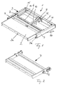
- Fig. 1 shows a boarding and / or access aid 1 with a tread plate 2, the od, for example, on a bus or the. Like. Is formed.
- the approach and / or access aid 1 according to FIG. 1 has a rectangular frame 3 with two parallel side parts 4, which are connected at rear ends by an end profile 5 and in a spaced apart, eg middle part by at least one support 6.
- the side parts 4 are preferably designed as inwardly open, U-shaped guides in which a trolley 7 (Fig. 2) is guided by means of wheels 8 slidably. At a front end of the trolley 7 is coupled to a rear end of the tread plate 2.
- the tread plate 2 by the trolley 7 parallel to the side members 4 pushed back and forth and thereby, based on the vehicle, not shown, either via a front end 3a of the frame 3 also in an extended, from Fig. 1st be pushed forward apparent position or in a retracted position in which a front edge 2a of the tread plate 2 is substantially flush with the front side 3a of the frame 3.
- the tread plate 2 may be pivotally coupled in a conventional manner with the trolley 7 to form a slightly downwardly inclined, leading to a standing or waiting area ramp in the extended state, if the stand or waiting area not level with the frame 3 is arranged.
- the footboard can also be provided with the wheels 8 in a rear area and the trolley 7 are completely omitted.
- a non-illustrated, rotatably mounted deflection roller is mounted, which cooperates with a drive roller 9 which is rotatably mounted on the end profile 5.
- Both rollers are arranged in the middle between the two side parts 4 and have parallel to the axes of the roller 8 (Fig. 2) of the trolley 7 extended axes of rotation.
- the two rollers are used to guide an endless, designed as a chain or toothed belt drive element 10, which is connected to a rear end of the trolley 7 or the tread plate 2 and in the middle between the side members 4 and extends parallel to these.
- a motor 11 For driving a motor 11 is provided which is mounted on the end profile 5 and has a coaxial with the axis of rotation of the drive roller 9 arranged output shaft 12 which is connected via a coupling, not shown, with a drive shaft of the drive roller 9.
- the motor 11 is preferably designed as a reversible motor, so that its output shaft can be selectively rotated in one or the other direction.
- the drive element 10 and with it also the trolley 7 and the tread plate 2 in the direction of a double arrow v (Fig. 1) back and forth.
- the trolley 7 is easily displaced, the side panels 4 with small tolerances (eg in the range of 1/10 mm) regardless of exactly parallel, how long they are in an individual case (eg up to 1500 mm) and how wide the frame 7 is (eg up to 1500 mm).
- the procedure according to the invention is as follows.
- the side parts 4, the end profile 5 and the support strut 6 are everywhere where they are to be connected, provided with positively interlocking positioning means.
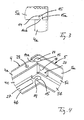
- Fig. 3 and 4 of which in Fig. 3 is a plan view of an upper right corner of the frame 3 in Fig. 1 and in Fig. 4 is a perspective view of an upper left in Fig. 1 corner of the frame 3, the side parts 4 and the end profile 5 have U-shaped cross sections and therefore two longitudinal webs 4a, 4b and 5a, 5b and one middle web 4c or 5c connecting the latter.
- the side parts 4 are provided at their ends connected to the end profile 5 with the longitudinal webs 4a, 4b integrally formed, first positioning means and the end profile 5 at its associated ends with formed in the longitudinal webs 5a, 5b second positioning means.
- the first positioning means are preferably made e.g. circular lugs 14 and connected thereto webs 14a, by means of which they are attached to the longitudinal webs 4a, 4b.
- the second positioning means preferably consist of the lugs 14 receiving circular recesses 15 and the webs 14 a receiving, opening in the recesses 15 slots 15 a, which also border on the edges of the longitudinal webs 5 a, 5 b. This makes it possible, in particular Fig.
- the side parts 4 and the end profile 5 are preferably made of U-shaped bent sheet metal parts.
- the side parts 4 and the end profile 5 are made of originally flat sheet metal blanks or the like in which the first and second positioning means 14, 14a and 15, 15a are formed by laser cutting, for example, with very close tolerances can be done.
- the blanks are longitudinally schematically indicated bending lines 16 and 17 (Fig. 5) are bent by 90 ° to the same side to obtain the U-shaped, from Fig. 4 apparent cross sections. It is clear that the bending lines 16, 17 are shown only schematically and the blanks are actually not edged sharp, but bent with small radii of curvature.
- mounting tabs 18 are additionally formed on the ends of the central webs 4c of the side parts 4 (and / or the ends of the central webs 5c of the end profile 5), which also along a further bending line 19 by about 90 ° and to the same Side as the longitudinal webs 4 a, 4 b bent and provided with screw holes 20.
- These mounting tabs 18 lie in connecting the end profile 5 with the side parts 4 from the inside and against the central webs 5c of the end profile 5 (or the respective side part 4), that their screw holes 20 formed in the central webs 5c (or 4c) screw holes 21 are aligned coaxially.
- the screw holes 20, 21 protruding mounting screws, the side parts 4 and the end profile 5 are then firmly connected to each other, their exact relative positioning is further determined by the first and second positioning means.
- the first and second positioning means 14, 14a and 15, 15a can be realized by triangular projections and recesses or those with other cross-sectional shapes instead of by circular projections and recesses. It is only important that the positioning means each fit together form fit and thereby set the relative positions of the side panels 4 and the end profiles 5 in the longitudinal and transverse directions clearly and with close tolerances. Therefore, it is of course also possible to form the first positioning means as recesses and the second positioning means as approaches or to provide combinations of both.
- the connection of the side parts 4 with the support strut 6 is expediently carried out in a corresponding manner, as shown in FIGS. 5, 7 and 8 show.
- the lower longitudinal webs 4b of the side parts 4 provided in FIGS. 1 and 8 are provided with third positioning means, which are basically designed like the second positioning means 15, 15a could be in the embodiment but have a slightly different shape. They consist in particular of recesses 25 with transversely to the side parts 4 and transverse to those bending lines 16 extending, preferably parallel side edges 25a, which border the side edges of the longitudinal webs 4b, and from the side edges 25a inwardly subsequent extensions 25b, so that the third positioning means 25, 25a, 25b consist overall of cutouts with a substantially T-shaped contour. These cutouts are advantageously made before the bending process and are like the recesses 15 and 15a slots open to the edges.
- Fig. 4 side part 4 is provided at its lower longitudinal ridge 4b with corresponding third positioning means, which, however, are formed mirror symmetry to the positioning means 25, 25a, 25b of FIG.
- the support strut 6 is provided at its two ends with fourth positioning means (FIGS. 7 and 8) in the form of ashes 26, which have an outer contour corresponding to the inner contour of the recesses 25 of the third positioning means and therefore inserted into the third positioning means with small tolerances and in a puzzle-like manner can be.
- fourth positioning means FIGS. 7 and 8
- the described shape of the third and fourth positioning means and in particular the presence of the side edges 25a and enschender side edges on the lugs 26 has the advantage that the support struts 6 come to lie largely secure against rotation in the side parts 4, i. the positioning means 25 and 26 do not act as a pivot bearing perpendicular to the plane formed by the longitudinal webs 4b and the support struts 6 preferably made of flat bars.
- the surfaces of the support struts 6 and the longitudinal webs 4b are preferably in a common plane.
- the production of the third and fourth positioning means 25, 26 takes place, like that of the first and second positioning means 14, 15, preferably by laser cutting and in the case of the side parts 4 before the bending operation (FIG. 5). Again, it is possible to form the third positioning means as lugs and the fourth positioning means as recesses or to provide combinations thereof.
- a solid connection of the side parts 4 with the support strut 6 is provided in the embodiment by means of rails 27 (Fig. 8), which are placed on the facing inner sides of the longitudinal webs 4a, 4b and not shown support and guidance of the wheels 8 of Trolley 7 (Fig. 2) are used.
- the rails 27 on their undersides preferably formed as blind holes, not shown threaded holes, which after the laying of the rails 27 on the longitudinal webs 4a, 4b on continuous, formed in the longitudinal webs 4a, 4b screw holes 28 (Fig. 8) are aligned. By screwed in from the outside fastening screws, the rails 27 are then fixed to the longitudinal webs 4a, 4b.
- the rails 27 shown in broken in Fig. 8 also have at least one threaded bore on at least one continuous screw hole 29 in the fourth Positioning means forming lugs 26 are aligned.
- a screw hole 29 protruding from the outside through fastening screw can therefore be screwed into the relevant threaded bore of the track 27 until her head from below on the fourth positioning means forming projection 26 and this firm with the slide rail 27 and on this with the frame. 3 (Fig. 1) connects.
- two or more attachment screws may be used per lug 26.
- a plurality of such support struts 6 can also be connected to the side parts 4, in particular also at the front end 3a (FIG. 1) of the frame 3. The connection can also be made in the manner described with reference to FIGS. 7 and 8.
- One of these support struts 6 can also serve for fastening the deflection pulley, not shown, for the drive element 10 (FIG. 1).
- Impellers 8 and drive parts 9 to 12 protects against contamination.
- This floor preferably has a pivotable service flap (FIG. 1) which can be pivoted downwards and, in spite of the cover, allows easy access to the drive parts 9 to 12 located in the rear area of the frame 3, which is particularly useful for service purposes (cleaning, Repair, maintenance, etc.) is advantageous and a cumbersome disassembly of the entire frame 3 od.
- a pivotable service flap (FIG. 1) which can be pivoted downwards and, in spite of the cover, allows easy access to the drive parts 9 to 12 located in the rear area of the frame 3, which is particularly useful for service purposes (cleaning, Repair, maintenance, etc.) is advantageous and a cumbersome disassembly of the entire frame 3 od.
- it may be provided to extend the floor only to the last rear support strut 6 and the service flap 30 by means of a hinge band od.
- a particularly significant advantage of the approach and / or access aid described is that the puzzle-like positioning means a very accurate arrangement of the parts 4, 5 and 6 relative to each other, thereby allowing a parallel alignment of the two side parts 4 and a total extremely torsionally rigid frame construction.
- the invention is not limited to the described embodiments, which can be modified in many ways. This is especially true for the shape and dimensioning of the positioning means, which, however, are preferably always formed so that they can be easily manufactured in the manner described. Further, it is possible to produce the first to fourth positioning means in other ways than by laser cutting, in particular for example by punching. For frames 3 small sizes, it may further be auseichend to provide the support strut 6 only at the front end 3a (Fig. 1) of the frame 3 instead of or only in a central part and possibly the service flap 30 omitted. Next, the Wheels 8 are also mounted in the rear of the tread plate 2, in which case an additional trolley is not needed. Finally, it should be understood that the various features may be applied in combinations other than those described and illustrated.
Landscapes
- Engineering & Computer Science (AREA)
- Mechanical Engineering (AREA)
- Vehicle Step Arrangements And Article Storage (AREA)
- Body Structure For Vehicles (AREA)
- Refuge Islands, Traffic Blockers, Or Guard Fence (AREA)
- Motorcycle And Bicycle Frame (AREA)
- Vehicle Waterproofing, Decoration, And Sanitation Devices (AREA)
- Traffic Control Systems (AREA)
- Bridges Or Land Bridges (AREA)
- Tents Or Canopies (AREA)
- Road Paving Structures (AREA)
- Handcart (AREA)
- Forklifts And Lifting Vehicles (AREA)
- Ladders (AREA)
Abstract
Description
- Die Erfindung betrifft eine Zustiegs- und/oder Zufahrtshilfe der im Oberbegriffs des Anspruchs 1 angegebenen Gattung.
- Zustiegs- und Zufahrtshilfen dieser Art sind in vielfältiger Form bekannt. Sie finden Anwendung bei Fahrzeugen zur Personenbeförderung, beispielsweise bei Bussen und Schienenfahrzeugen des öffentlichen Nahverkehrs, und erleichtern den Ein- und Ausstieg bei solchen Fahrzeugen dadurch, daß im Bereich von Haltestellen eine am jeweiligen Fahrzeug verschiebbar und ggf. auch verschwenkbar gelagerte Trittplatte in Form einer Rampe, eines linearen Tritts od. dgl. ausgefahren wird. Die Bezeichnung Zustiegs- und Zufahrtshilfe beinhaltet selbstverständlich auch deren Verwendung als Ausstiegs- und Ausfahrthilfe.
- Die beispielsweise aus Aluminium bestehende und mit einer rutschhemmenden Auflage versehene Trittplatte ist mit ihrer Rückseite an einen Rollwagen gekoppelt, der in unterhalb des Fahrzeugbodens angebrachten Laufschienen verschiebbar gelagert ist. Sie wird vorzugsweise vor dem Öffnen einer Fahrzeugtür zwischen einem Stand-und Wartebereich für zu befördernde Personen, beispielsweise einem Bahnsteig, und einer Bodenfläche im Einstiegsbereich des Fahrzeugs positioniert, um eventuell zwischen diesen beiden Bereichen bestehende Niveauunterschiede und/oder Spalte auszugleichen oder einfacher passierbar zu machen. Dadurch wird es beispielsweise auch Rollstuhlfahrern und Kinderwagenbenutzern möglich, einfach ein- bzw. auszusteigen. Nach Beendigung der Aus- und Einstiegsphase und evtl. nach dem Schließen der Fahrzeugtüren wird die Trittplatte wieder in ihre Ausgangsposition zurückgebracht.
- Damit die Trittplatte zusammen mit den zugehörigen Funktionsteilen als komplette Baueinheit montiert werden kann, sind die Laufschienen für den Rollwagen an den Seitenteilen eines rechteckigen Rahmens befestigt, an dem auch die zum Hin- und Herfahren des Rollwagens benötigten Antriebsmittel montiert sind. Der Rahmen besteht insgesamt aus einer Schweißkontruktion und wird unter dem Fahrzeugboden montiert.
- Zur Erzielung einer exakten Spurführung müssen die Seitenteile und die an ihnen befestigten Laufschienen exakt parallel zueinander ansgerichtet sein. Das gilt insbesondere dann, wenn es erwünscht ist, den Rollwagen zur Reduzierung der Herstellungskosten nur mit einem einzigen, in der Mitte zwischen den Seitenteilen wirksamen Antrieb zu versehen.
- Aufgrund der erforderlichen Schweißarbeiten beim Zusammenbau der den Rahmen bildenden Seitenteile, Endprofile und Stützstreben kann eine exakte Parallelität nicht gewährleistet werden. Aus denselben Gründen ist die Einhaltung vorgegebener Toleranzen im Hinblick auf das Längen- und Breitenmaß des Rahmens schwierig. Es ist daher erforderlich, die Parallelität der Laufschienen und/oder eine leichtgängige Verschiebbarkeit des Rollwagens auf andere Weise sicherzustellen. Dazu werden einerseits zusätzliche Arbeitsschritte bei der Herstellung und/oder beim Zusammenbau des Rahmens benötigt, was mit einer unerwünschten Steigerung der Produktionskosten verbunden ist. Andererseits müssen vergleichsweise große Herstellungstoleranzen in Kauf genommen werden, was ebenfalls in der Regel unerwünscht ist.
- Ausgehend davon liegt der Erfindung das technische Problem zugrunde, die Zustiegs-und/oder Zufahrtshilfe der eingangs bezeichneten Gattung mit einem Rahmen zu versehen, der mit engen Toleranzen und dennoch vergleichsweise preisgünstig herstellbar ist.
- Zur Lösung dieses Problems wird erfindungsgemäß vorgeschlagen, die Seitenteile, das Endprofil und die Stützstrebe(n) des Rahmens mit formschlüssig ineinander greifenden Positionierungsmitteln zu versehen.
- Durch die erfindungsgemäßen Positionierungsmittel ist nicht nur Länge und Breite des Rahmens festgelegt, sondern auch sichergestellt, daß die Seitenteile exakt parallel angeordnet werden. Der erfindungsgemäße Rahmen bringt daher vor allem in der Serienfertigung erhebliche Vorteile mit sich. Das gilt insbesondere dann, wenn die Positionierungsmittel nach Art von Puzzleteilen aus ineinander greifenden Aussparungen und Ansätzen bestehen. Derartige Aussparungen und Ansätze lassen sich mit hoher Präzision beispielsweise durch Stanzen, mit besonderem Vorteil jedoch durch Laserschneiden herstellen. Außerdem ermöglicht es die Erfindung, die Rahmenteile, soweit erforderlich, trotz des Vorhandenseins der Positionierungsmittel als U-förmig gebogene Blechformteile herzustellen, was die Produktionskosten erniedrigt, ohne die engen Toleranzen zu erhöhen.
- Weitere vorteilhafte Merkmale der Erfindung ergeben sich aus den Unteransprüchen.
- Die Erfindung wird nachfolgend in Verbindung mit den beiligenden Zeichnungen an Ausführungsbeispielen näher erläutert. Es zeigen:
- Fig. 1 eine schematische perspektivische Ansicht einer erfindungsgemäßen Zustiegs-und/oder Zufahrtshilfe mit einem Rahmen und einer an diesem ein- und ausfahrbar gelagerten Trittplatte;
- Fig. 2 eine schematische perspektivische Ansicht eines in dem Rahmen der Zustiegs-und/oder Zufahrtshilfe nach Fig. 1 verschiebbar geführten, mit der Trittplatte gekoppelten Rollwagens;
- Fig. 3 eine Draufsicht auf ein Ausführungsbeispiel von erfindungsgemäßen, zur Verbindung von zwei Rahmenteilen bestimmten Positionierungsmitteln;
- Fig. 4 eine perspektivische Darstellung einer Eckverbindung zwischen einem Seitenteil und einem Endprofil des Rahmens nach Fig. 1;
- Fig. 5 eine schematische Draufsicht auf einen zur Herstellung des Seitenteils und des Endprofils nach Fig. 4 verwendeten Blechzuschnitts;
- Fig. 6 ein zweites Ausführungsbeispiel von entsprechend Fig. 3 verwendbaren Positionierungsmitteln;
- Fig. 7 eine Unteransicht einer Verbindung zwischen einem Seitenteil und einer Stützstrebe des Rahmens nach Fig. 1; und
- Fig. 8 die Verbindung nach Fig. 7 in einer perspektivischen Ansicht von oben her.
- Fig. 1 zeigt ein Zustiegs- und/oder Zufahrtshilfe 1 mit einer Trittplatte 2, die z.B. an einem Autobus od. dgl. ausgebildet ist. Die Zustiegs- und/oder Zufahrtshilfe 1 nach Fig. 1 weist einen rechteckförmigen Rahmen 3 mit zwei parallelen Seitenteilen 4 auf, die an hinteren Enden durch ein Endprofil 5 und in einem davon beabstandeten, z.B. mittleren Teil durch wenigstens eine Stütze 6 verbunden sind. Die Seitenteile 4 sind vorzugsweise als nach innen offene, U-förmige Führungen ausgebildet, in denen ein Rollwagen 7 (Fig. 2) mittels Laufrädern 8 verschiebbar geführt ist. An einem Vorderende ist der Rollwagen 7 an ein Hinterende der Trittplatte 2 gekoppelt. Dadurch kann die Trittplatte 2 vom Rollwagen 7 parallel zu den Seitenteilen 4 vor- und zurückgeschoben und dadurch, bezogen auf das nicht gezeigte Fahrzeug, entweder über ein Vorderende 3a des Rahmens 3 hinaus in eine ausgefahrene, aus Fig. 1 ersichtliche Position vorgeschoben oder in eine eingefahrene Position zurückgezogen werden, in welcher eine Vorderkante 2a der Trittplatte 2 im wesentlichen bündig mit der Vorderseite 3a des Rahmens 3 abschließt. Außerdem kann die Trittplatte 2 in an sich bekannter Weise schwenkbar mit dem Rollwagen 7 gekoppelt sein, um im ausgefahrenen Zustand eine leicht nach unten geneigte, zu einem Stand- oder Wartebereich führende Rampe zu bilden, sofern der Stand- oder Wartebereich nicht niveaugleich mit dem Rahmen 3 angeordnet ist.
- Ist eine Verschwenkung der Trittplatte nicht erforderlich, kann sie in einem hinteren Bereich auch selbst mit den Laufrädern 8 versehen sein und der Rollwagen 7 ganz weggelassen werden.
- In einem vorderen Bereich des Rahmens 3 ist eine nicht dargestellte, drehbar gelagerte Umlenkrolle montiert, die mit einer Antriebsrolle 9 zusammenwirkt, die am Endprofil 5 drehbar gelagert ist. Beide Rollen sind in der Mitte zwischen den beiden Seitenteilen 4 angeordnet und weisen parallel zu den Achsen der Laufrolle 8 (Fig. 2) des Rollwagens 7 erstreckte Drehachsen auf. Die beiden Rollen dienen zur Führung eines endlosen, z.B. als Kette oder Zahnriemen ausgebildeten Antriebselements 10, das mit einem hinteren Ende des Rollwagens 7 oder der Trittplatte 2 verbunden und in der Mitte zwischen den Seitenteilen 4 und parallel zu diesen erstreckt ist. Zum Antrieb ist ein Motor 11 vorgesehen, der am Endprofil 5 montiert ist und eine koaxial zur Drehachse der Antriebsrolle 9 angeordnete Abtriebswelle 12 aufweist, die über eine nicht dargestellte Kupplung mit einer Antriebswelle der Antriebsrolle 9 verbunden ist. Der Motor 11 ist vorzugsweise als Reversiermotor ausgebildet, so daß seine Abtriebswelle wahlweise in der einen oder anderen Drehrichtung gedreht werden kann. Dadurch sind das Antriebselement 10 und mit ihm auch der Rollwagen 7 und die Trittplatte 2 in Richtung eines Doppelpfeils v (Fig. 1) hin- und herbewegbar.
- Damit der Rollwagen 7 leichtgängig verschiebbar ist, müssen die Seitenteile 4 mit geringen Toleranzen (z.B. im Bereich von 1/10 mm) unabhängig davon exakt parallel angeordnet sein, wie lang sie im Einzelfall sind (z.B. bis zu 1500 mm) und wie breit der Rahmen 7 ist (z.B. bis zu 1500 mm). Um dies zu erreichen, wird erfindungsgemäß wie folgt vorgegangen.
- Die Seitenteile 4, das Endprofil 5 und die Stützstrebe 6 werden überall dort, wo sie miteinander verbunden werden sollen, mit formschlüssig ineinander greifenden Positionierungsmitteln versehen. Bei dem in Fig. 3 und 4 gezeigten Ausführungsbeispiel, von dem in Fig. 3 eine Draufsicht auf eine in Fig. 1 obere, rechte Ecke des Rahmens 3 und in Fig. 4 eine perspektivische Ansicht einer in Fig. 1 linken oberen Ecke des Rahmens 3 gezeigt ist, haben die Seitenteile 4 und das Endprofil 5 U-förmige Querschnitte und daher je zwei Längsstege 4a, 4b bzw. 5a, 5b und je einen diese verbindenden Mittelsteg 4c bzw. 5c. Ferner sind die Seitenteile 4 an ihren mit dem Endprofil 5 verbundenen Enden mit an die Längsstege 4a, 4b angeformten, ersten Positionierungsmitteln und das Endprofil 5 an seinen zugeordneten Enden mit in den Längsstegen 5a, 5b ausgebildeten zweiten Positionierungsmitteln versehen. Die ersten Positionierungsmittel bestehen vorzugsweise aus z.B. kreisförmigen Ansätzen 14 und mit diesen verbundenen Stegen 14a, mittels derer sie an den Längsstegen 4a, 4b angebracht sind. Dagegen bestehen die zweiten Positionierungsmittel vorzugsweise aus die Ansätze 14 aufnehmenden kreisförmigen Aussparungen 15 und die Stege 14a aufnehmenden, in den Aussparungen 15 mündenden Schlitzen 15a, die außerdem an die Ränder der Längsstege 5a, 5b grenzen. Dadurch ist es möglich, wie insbesondere Fig. 3 und 4 zeigen, das Endprofil 5 an seinen Enden auf die Seitenteile 4 so aufzustecken, daß die Ansätze 14 und die Stege 14a nach Art eines Puzzles in die Aussparungen 15 und die Schlitze 15a eintreten und dann in diesen formschlüssig und mit exakter relativer Positionierung gehalten werden.
- Die Seitenteile 4 und das Endprofil 5 bestehen vorzugsweise aus U-förmig gebogenen Blechformteilen. Wie insbesondere Fig. 5 zeigt, werden die Seitenteile 4 und das Endprofil 5 aus ursprünglich flachen Blechzuschnitten od. dgl. hergestellt, in denen die ersten und zweiten Positionierungsmittel 14, 14a und 15, 15a z.B. durch Laserschneiden ausgebildet werden, was mit sehr engen Toleranzen erfolgen kann. Im Anschluß daran werden die Blechzuschnitte längs schematisch angedeuteter Biegelinien 16 bzw. 17 (Fig. 5) um jeweils 90 ° zu derselben Seite hin umgebogen, um die U-förmigen, aus Fig. 4 ersichtlichen Querschnitte zu erhalten. Dabei ist klar, daß die Biegelinien 16, 17 nur schematisch dargestellt sind und die Zuschnitte tatsächlich nicht scharfkantig abgekantet, sondern mit kleinen Krümmungsradien umgebogen werden.
- Wie Fig. 5 weiter zeigt, werden an die Enden der Mittelstege 4c der Seitenteile 4 (und/oder die Enden der Mittelstege 5c des Endprofils 5) zusätzlich Befestigungslaschen 18 angeformt, die längs einer weiteren Biegelinie 19 ebenfalls um ca. 90° und zu derselben Seite wie die Längsstege 4a, 4b umgebogen und mit Schraublöchern 20 versehen werden. Diese Befestigungslaschen 18 legen sich beim Verbinden des Endprofils 5 mit den Seitenteilen 4 von innen und derart gegen die Mittelstege 5c des Endprofils 5 (bzw. des betreffenden Seitenteils 4), daß ihre Schraublöcher 20 auf in den Mittelstegen 5c (bzw. 4c) ausgebildete Schraublöcher 21 koaxial ausgerichtet sind. Mit Hilfe von nicht dargestellten, die Schraublöcher 20, 21 durchragender Befestigungsschrauben werden die Seitenteile 4 und das Endprofil 5 dann fest miteinander verbunden, wobei ihre exakte relative Positionierung auch weiterhin durch die ersten und zweiten Positionierungsmittel vorgegeben ist.
- Die ersten und zweiten Positionierungsmittel 14, 14a und 15, 15a können anstatt durch kreisförmige Ansätze und Aussparungen auch durch dreieckige Ansätze und Aussparungen oder solche mit anderen Querschnittsformen realisiert werden. Wichtig ist nur, daß die Positionierungsmittel jeweils formschlüssig zusammenpassen und dadurch die relativen Lagen der Seitenteile 4 und der Endprofile 5 in Längs- und Querrichtung eindeutig und mit engen Toleranzen festlegen. Daher ist es natürlich auch möglich, die ersten Positionierungsmittel als Aussparungen und die zweiten Positionierungsmittel als Ansätze auszubilden oder jeweils Kombinationen von beiden vorzusehen.
- Die Verbindung der Seitenteile 4 mit der Stützstrebe 6 erfolgt zweckmäßig in entsprechender Weise, wie Fig. 5, 7 und 8 zeigen. Im Ausführungsbeispiel sind die in Fig. 1 und 8 unteren Längsstege 4b der Seitenteile 4 mit dritten Positionierungsmitteln versehen, die grundsätzlich wie die zweiten Positionierungsmitteln 15, 15a ausgebildet sein könnten, im Ausführungsbeispiel aber eine etwas andere Form haben. Sie bestehen insbesondere aus Aussparungen 25 mit quer zu den Seitenteilen 4 bzw. quer zu denen Biegelinien 16 verlaufenden, vorzugsweise parallelen Seitenkanten 25a, die an die Seitenränder der Längsstege 4b grenzen, sowie aus an die Seitenkanten 25a nach innen hin anschließenden Erweiterungen 25b, so daß die dritten Positionierungsmittel 25, 25a, 25b insgesamt aus Ausschnitten mit einer im wesentlichen T-förmigen Kontur bestehen. Diese Ausschnitte werden zweckmäßig vor dem Biegevorgang hergestellt und sind wie die Aussparungen 15 und Schlitze 15a zu den Rändern hin offen.
- Das andere, in Fig. 4 nicht sichtbare Seitenteil 4 wird an seinem unteren Längssteg 4b mit entsprechenden dritten Positionierungsmitteln versehen, die jedoch spiegelsymmmetrisch zu den Positionierungsmitteln 25, 25a, 25b gemäß Fig. 5 ausgebildet sind.
- Die Stützstrebe 6 wird an ihren beiden Enden mit vierten Positionierungsmitteln (Fig. 7 und 8) in Form von Asätzen 26 versehen, die eine der Innenkontur der Aussparungen 25 der dritten Positionierungsmittel entsprechende Außenkontur haben und daher mit geringen Toleranzen und puzzleartig in die dritten Positionierungsmittel eingelegt werden können. Dabei bringt die beschriebene Form der dritten und vierten Positionierungsmittel und insbesondere das Vorhandensein der Seitenkanten 25a und ensprechender Seitenkanten an den Ansätzen 26 den Vorteil mit sich, daß die Stützstreben 6 weitgehend verdrehsicher in den Seitenteilen 4 zu liegen kommen, d.h. die Positionierungsmittel 25 und 26 nicht als Schwenklager senkrecht zu der von den Längsstegen 4b und den vorzugsweise aus Flachstäben hergestellten Stützstreben 6 gebildeten Ebene wirken. Nach dem Einlegen der vierten Positionierungsmittel 26 in die dritten Positionierungsmittel 25, 25a, 25b liegen die Oberflächen der Stützstreben 6 und der Längsstege 4b vorzugsweise in einer gemeinsamen Ebene.
- Die Herstellung der dritten und vierten Positionierungsmittel 25, 26 erfolgt wie die der ersten und zweiten Positionierungsmittel 14, 15 vorzugsweise durch Laserschneiden und bei den Seitenteilen 4 vor dem Biegevorgang (Fig. 5). Auch hier ist es möglich, die dritten Positionierungsmittel als Ansätze und die vierten Positionierungsmittel als Aussparungen auszubilden oder Kombinationen davon vorzusehen.
- Eine feste Verbindung der Seitenteile 4 mit der Stützstrebe 6 wird im Ausführungsbeispiel mit Hilfe von Laufschienen 27 (Fig. 8) geschaffen, die auf die einander zugewandten Innenseiten der Längsstege 4a, 4b aufgelegt werden und zur nicht näher dargestellten Abstützung und Führung der Laufräder 8 des Rollwagens 7 (Fig. 2) dienen. Zu diesem Zweck weisen die Laufschienen 27 an ihren Unterseiten vorzugsweise als Blindbohrungen ausgebildete, nicht dargestellte Gewindebohrungen auf, die nach dem Auflegen der Laufschienen 27 auf die Längsstege 4a, 4b auf durchgehende, in den Längsstegen 4a, 4b ausgebildete Schraublöcher 28 (Fig. 8) ausgerichtet sind. Durch von außen her eingedrehte Befestigungsschrauben werden die Laufschienen 27 sodann an den Längsstegen 4a, 4b fixiert.
- An denjenigen Stellen, an denen die die dritten Positionierungsmittel bildenden Aussparungen bzw. Ausschnitte 25 (Fig. 5) liegen, weisen die in Fig. 8 unterbrochen dargestellten Laufschienen 27 ebenfalls wenigstens eine Gewindebohrung auf, die auf wenigstens ein durchgehendes Schraubloch 29 in den die vierten Positionierungsmittel bildenden Ansätzen 26 ausgerichtet sind. Eine das Schraubloch 29 von außen her durchragende Befestigungsschraube kann daher in die betreffende Gewindebohrung der Laufschiene 27 eingedreht werden, bis ihr Kopf von unten an dem das vierte Positionierungsmittel bildenden Ansatz 26 anliegt und diesen dadurch fest mit der Laufschiene 27 und über diese mit dem Rahmen 3 (Fig. 1) verbindet. Natürlich können auch wie gezeigt zwei oder mehr Befestigungsschrauben pro Ansatz 26 verwendet werden.
- Bei Bedarf können ferner mehrere derartige Stützstreben 6 mit den Seitenteilen 4 verbunden werden, insbesondere auch an dem Vorderende 3a (Fig. 1) des Rahmens 3. Die Verbindung kann dabei ebenfalls auf die anhand der Fig. 7 und 8 beschriebene Weise erfolgen. Eine dieser Stützstreben 6 kann außerdem zur Befestigung der nicht gezeigten Umlenkrolle für das Antriebselement 10 (Fig. 1) dienen.
- An den Unterseiten der Längsstege 4b, 5b der Seitenteile 4 und des Endprofils 5 und ggf. der Stützstreben(n) 6 kann ein den Rahmen 3 nach unten hin abdeckender, nicht dargestellter Boden befestigt sein, der den Innenraum des Rahmens 3 und die darin befindlichen Laufräder 8 und Antriebsteile 9 bis 12 vor Verunreinigungen schützt. Dieser Boden weist vorzugsweise eine schwenkbare Serviceklappe (Fig. 1) auf, die nach unten schwenkbar ist und trotz der Abdeckung bei Bedarf einen einfachen Zugang zu den im hinteren Bereich des Rahmens 3 liegenden Antriebsteilen 9 bis 12 ermöglicht, was insbesondere für Servicezwecke (Reinigung, Reparatur, Wartung usw.) vorteilhaft ist und eine umständliche Demontage des ganzen Rahmens 3 od. dgl. unnötig macht. Alternativ kann vorgesehen sein, den Boden nur bis zu der letzten hinteren Stützstrebe 6 zu erstrecken und die Serviceklappe 30 mittels eines Scharnierbandes od. dgl. schwenkbar an dieser Stützstrebe 6 zu befestigen.
- Ein besonders wesentlicher Vorteil der beschriebenen Zustiegs- und/oder Zufahrtshilfe besteht darin, daß die puzzleartigen Positionierungsmittel eine sehr genaue Anordnung der Teile 4, 5 und 6 relativ zueinander, dadurch eine parallele Ausrichtung der beiden Seitenteile 4 und eine insgesamt äußerst verwindungssteife Rahmenkonstruktion ermögichen. Außerdem lassen sich leicht Rahmen 3 mit unterschiedlichen Abmessungen herstellen, da es hierfür nur erforderlich ist, unterschiedlich lange Seitenteile 4, Endprofile 5 und Stützstreben 6 vorzusehen, die sämtlich dieselben ersten bis vierten Positionierungsmittel aufweisen können.
- Die Erfindung ist nicht auf die beschriebenen Ausführungsbeispiele beschränkt, die auf vielfache Weise abgewandelt werden können. Das gilt insbesondere für die Form und die Dimensionierung der Positionierungsmittel, die allerdings vorzugsweise stets so ausgebildet werden, daß sie in der beschriebenen Weise einfach gefertigt werden können. Weiter ist es möglich, die ersten bis vierten Positionierungsmittel auf andere Weise als durch Laserschneiden, insbesondere z.B. durch Stanzen herzustellen. Bei Rahmen 3 kleiner Baugrößen kann es weiterhin auseichend sein, die Stützstrebe 6 nur am Vorderende 3a (Fig. 1) des Rahmens 3 anstatt auch oder nur in einem mittleren Teil vorzusehen und ggf. die Serviceklappe 30 entfallen zu lassen. Weiter können die Laufräder 8 auch im hinteren Bereich der Trittplatte 2 angebracht werden, in welchem Fall ein zusätzlicher Rollwagen nicht benötigt wird. Schließlich versteht sich, daß die verschiedenen Merkmale auch in anderen als den beschriebenen und dargestellten Kombinationen angewendet werden können.
Claims (14)
- Zustiegs- und/oder Zufahrtshilfe für Fahrzeuge zur Personenbeförderung mit einem rechteckförmigen Rahmen (3), der zwei parallel angeordnete Seitenteile (4) aufweist, die an hinteren Enden durch ein Endprofil (5) und in einem davon beabstandeten Bereich durch wenigstens eine Stützstrebe (6) fest miteinander verbunden sind, und mit einer an den Seitenteilen (4) fahrbar gelagerten Trittplatte (2), dadurch gekennzeichnet, daß die Seitenteile (4), das Endprofil (5) und die Stützstrebe (6) mit formschlüssig ineinander greifenden Positionierungsmitteln (14, 14a, 15, 15a; 25, 25a, 25b, 26) versehen sind.
- Zustiegs- und/oder Zufahrtshilfe nach Anspruch 1, dadurch gekennzeichnet, daß die Seitenteile (4) je einen Mittelsteg (4c) und zwei U-förmig mit diesem verbundene Längsstege (4a, 4b) aufweisen und die Längsstege (4a, 4b) an ihren Enden mit ersten Positionierungsmitteln (14, 14a) versehen sind, die mit an zugeordneten Enden des Endprofils (5) ausgebildeten zweiten Positionierungsmitteln (15, 15a) formschlüssig zusammenwirken.
- Zustiegs- und/oder Zufahrtshilfe nach Anspruch 2, dadurch gekennzeichnet, daß das Endprofil (5) einen Mittelsteg (5c) und zwei U-förmig mit diesem verbundene Längsstege (5a, 5b) aufweist und die Längsstege (5a, 5b) an ihren Enden mit den zweiten Positionierungsmitteln (15, 15a) versehen sind.
- Zustiegs- und/oder Zufahrtshilfe nach Anspruch 2 oder 3, dadurch gekennzeichnet, daß je einer der Längsstege (4b) der Seitenteile (4) mit wenigstens je einem dritten Positionierungsmittel (25, 25a, 25b) versehen ist und die Stützstrebe (6) an ihren Enden vierte, mit den dritten Positionierungsmitteln (25, 25a, 25b) formschlüssig zusammenwirkende Positionierungsmittel (26) aufweist.
- Zustiegs- und/oder Zufahrtshilfe nach einem der Ansprüche 1 bis 4, dadurch gekennzeichnet, daß die zweiten und/oder dritten Positionierungsmittel aus Aussparungen (15, 15a; 25, 25a, 25b) und die ersten und/oder vierten Positionierungsmittel aus in diese eingesetzten Ansätzen (14, 14a; 26) bestehen.
- Zustiegs- und/oder Zufahrtshilfe nach einem der Ansprüche 1 bis 5, dadurch gekennzeichnet, daß die Seitenteile (4) und das Endprofil (5) aus U-förmig gebogenen Blechformteilen bestehen.
- Zustiegs- und/oder Zufahrtshilfe nach einem der Ansprüche 1 bis 6, dadurch gekennzeichnet, daß die Stützstrebe (6) aus einem Flachstab besteht.
- Zustiegs- und/oder Zufahrtshilfe nach einem der Ansprüche 1 bis 7, dadurch gekennzeichnet, daß auf einander zugewandten Innenseiten der Längsstege (4a, 4b) der Seitenteile (4) je eine Laufschiene (27) für an der Trittplatte (2) oder einem an diese angekoppelten Rollwagen (7) drehbar gelagerte Laufräder (8) befestigt ist.
- Zustiegs- und/oder Zufahrtshilfe nach Anspruch 8, dadurch gekennzeichnet, daß die dritten Positionierungsmittel aus Aussparungen (25, 25a, 25b) in unteren Längsstegen (4b) der Seitenteile (4) und die vierten Positionierungsmittel aus in diese Aussparungen (25, 25a, 25b) passenden Ansätzen (26) bestehen und daß die Stützstrebe (6) mittels die Ansätze (26) durchragender Schrauben an den Laufschienen (27) befestigt sind.
- Zustiegs- und/oder Zufahrtshilfe nach einem der Ansprüche 1 bis 9, dadurch gekennzeichnet, daß die Positionierungsmittel (14, 14a, 15, 15a; 25, 25a, 25b, 26) durch Laserschneiden hergestellt sind.
- Zustiegs- und/oder Zufahrtshilfe nach einem der Ansprüche 1 bis 10, dadurch gekennzeichnet, daß die Seitenteile (4) und/oder das Endprofil (5) an ihren Enden mit der gegenseitigen Befestigung dienenden, abgewinkelten Befestigungslaschen (18) versehen sind.
- Zustiegs- und/oder Zufahrtshilfe nach Anspruch 11, dadurch gekennzeichnet, daß die Befestigungslaschen (18) mit Schraublöchern (20) versehen sind.
- Zustiegs- und/oder Zufahrtshilfe nach einem der Ansprüche 1 bis 12, dadurch gekennzeichnet, daß an den Unterseiten der Seitenteile (4) und/oder des Endprofils (5) ein den Innenraum des Rahmen (3) abdeckender Boden befestigt ist.
- Zustiegs- und/oder Zufahrtshilfe nach Anspruch 13, dadurch gekennzeichnet, daß der Rahmen (3) in einem hinteren Bereich eine nach unten schwenkbare Serviceklappe (30) aufweist.
Priority Applications (1)
| Application Number | Priority Date | Filing Date | Title |
|---|---|---|---|
| PL07022732T PL1925499T3 (pl) | 2006-11-24 | 2007-11-23 | Środek pomagający przy wsiadaniu i/lub podjeżdżaniu dla pojazdów do transportu osób |
Applications Claiming Priority (1)
| Application Number | Priority Date | Filing Date | Title |
|---|---|---|---|
| DE102006056112A DE102006056112A1 (de) | 2006-11-24 | 2006-11-24 | Zustiegs- und/oder Zufahrtshilfe für Fahrzeuge mit Personenbeförderung |
Publications (3)
| Publication Number | Publication Date |
|---|---|
| EP1925499A2 true EP1925499A2 (de) | 2008-05-28 |
| EP1925499A3 EP1925499A3 (de) | 2009-07-01 |
| EP1925499B1 EP1925499B1 (de) | 2011-04-20 |
Family
ID=39078428
Family Applications (1)
| Application Number | Title | Priority Date | Filing Date |
|---|---|---|---|
| EP07022732A Not-in-force EP1925499B1 (de) | 2006-11-24 | 2007-11-23 | Zustiegs- und/oder Zufahrtshilfe für Fahrzeuge mit Personenbeförderung |
Country Status (9)
| Country | Link |
|---|---|
| US (1) | US7926827B2 (de) |
| EP (1) | EP1925499B1 (de) |
| AT (1) | ATE506224T1 (de) |
| CA (1) | CA2612335A1 (de) |
| DE (2) | DE102006056112A1 (de) |
| ES (1) | ES2365421T3 (de) |
| NO (1) | NO20076016L (de) |
| PL (1) | PL1925499T3 (de) |
| RU (1) | RU2457963C2 (de) |
Cited By (1)
| Publication number | Priority date | Publication date | Assignee | Title |
|---|---|---|---|---|
| GB2457541A (en) * | 2008-02-19 | 2009-08-26 | William Stuart Hickie Taylor | A catch for retaining a slide out step in a deployed position |
Families Citing this family (11)
| Publication number | Priority date | Publication date | Assignee | Title |
|---|---|---|---|---|
| US8177247B1 (en) * | 2010-03-06 | 2012-05-15 | Jeffery Carr | Pullout step for vehicles |
| US9902326B2 (en) | 2010-03-06 | 2018-02-27 | Jeffrey Carr | Auxiliary step for vehicles |
| USD652776S1 (en) * | 2010-04-06 | 2012-01-24 | Michael P. Ziaylek | Automated retractable step apparatus |
| DE102012001321A1 (de) * | 2012-01-25 | 2013-07-25 | Liebherr-Hausgeräte Lienz Gmbh | Rahmen |
| US10328908B2 (en) * | 2015-10-23 | 2019-06-25 | Gebr. Bode Gmbh & Co. Kg | Pneumatic footplate cleaning |
| CN108169231A (zh) * | 2018-01-24 | 2018-06-15 | 南京图思灵智能科技有限责任公司 | 一种大容量的病理切片扫描仪 |
| US10710508B1 (en) | 2019-12-17 | 2020-07-14 | Miles A. Reitnouer | Extendable/retractable step assembly for a rear assembly of a flatbed trailer |
| JP7327328B2 (ja) * | 2020-09-10 | 2023-08-16 | トヨタ自動車株式会社 | 車両底部構造 |
| CN114290999B (zh) * | 2022-01-06 | 2023-04-25 | 广东科学技术职业学院 | 一种轻量化全承载纯电动城市客车前部结构 |
| IT202300001152A1 (it) * | 2023-01-26 | 2024-07-26 | Lci Italy Srl | Pedana retrattile con gradino estraibile, per aperture di accesso a veicoli |
| CN116552393B (zh) * | 2023-04-25 | 2026-04-03 | 江铃汽车股份有限公司 | 一种车载扶梯的调节装置 |
Citations (1)
| Publication number | Priority date | Publication date | Assignee | Title |
|---|---|---|---|---|
| WO1998006370A1 (en) | 1996-08-15 | 1998-02-19 | Tieman Industries Pty. Ltd. | A retractable ramp assembly |
Family Cites Families (15)
| Publication number | Priority date | Publication date | Assignee | Title |
|---|---|---|---|---|
| DE1906283U (de) * | 1964-08-19 | 1964-12-10 | Christian Steeb | Eckverbindung von aus einem starren material bestehenden winkelprofilen. |
| US3341223A (en) * | 1965-09-01 | 1967-09-12 | Wampfler Jacob | Retractible safety steps |
| DE1906283A1 (de) | 1969-02-08 | 1970-09-03 | Gewerk Eisenhuette Westfalia | Einbauvorrichtung fuer Tuebbingsegmente |
| SU591342A1 (ru) * | 1976-04-26 | 1978-02-05 | Всесоюзный Конструкторско-Экспериментальный Институт Автобусостроения | Выдвижна подножка транспортного средства |
| US4185849A (en) * | 1978-02-03 | 1980-01-29 | Jaeger Wilbert J | Retractable step for motor vehicle |
| DE3149876C2 (de) * | 1981-12-16 | 1985-06-05 | Siemens AG, 1000 Berlin und 8000 München | Leuchtenrahmen |
| US4479737A (en) * | 1982-02-01 | 1984-10-30 | Bergh Bros. Co., Inc. | Positive interlock |
| DE19632169A1 (de) * | 1996-08-09 | 1998-02-12 | Schmolz & Bickenbach | Profilvorrichtung für Schaltschränke und Verfahren ihrer Herstellung |
| AUPQ052199A0 (en) * | 1999-05-21 | 1999-06-17 | Wiltin Pty Ltd | Joining arrangements for structural members |
| JP2003072466A (ja) * | 2001-09-03 | 2003-03-12 | Mamoru Ueno | 乗降用ステップ台 |
| US20030071434A1 (en) * | 2001-10-16 | 2003-04-17 | Budd Alfred L. | Dual function passenger access system for a vehicle |
| BE1015086A6 (nl) | 2002-08-29 | 2004-09-07 | Omnistor Accessories Nv | Uitschuifbare trede. |
| US7171908B2 (en) * | 2003-03-19 | 2007-02-06 | Wabtec Holding Corp. | High/Low passenger ingress and egress conversion for transit vehicle |
| US6880843B1 (en) * | 2003-05-28 | 2005-04-19 | Melville T. Greer, Jr. | Vehicle step device |
| GB2405852A (en) * | 2003-09-13 | 2005-03-16 | Manganese Bronze Components Lt | Ramp assembly |
-
2006
- 2006-11-24 DE DE102006056112A patent/DE102006056112A1/de not_active Withdrawn
-
2007
- 2007-11-23 AT AT07022732T patent/ATE506224T1/de active
- 2007-11-23 ES ES07022732T patent/ES2365421T3/es active Active
- 2007-11-23 PL PL07022732T patent/PL1925499T3/pl unknown
- 2007-11-23 DE DE502007006987T patent/DE502007006987D1/de active Active
- 2007-11-23 NO NO20076016A patent/NO20076016L/no not_active Application Discontinuation
- 2007-11-23 EP EP07022732A patent/EP1925499B1/de not_active Not-in-force
- 2007-11-26 US US11/944,706 patent/US7926827B2/en not_active Expired - Fee Related
- 2007-11-26 CA CA002612335A patent/CA2612335A1/en not_active Abandoned
- 2007-11-26 RU RU2007143997/11A patent/RU2457963C2/ru not_active IP Right Cessation
Patent Citations (1)
| Publication number | Priority date | Publication date | Assignee | Title |
|---|---|---|---|---|
| WO1998006370A1 (en) | 1996-08-15 | 1998-02-19 | Tieman Industries Pty. Ltd. | A retractable ramp assembly |
Cited By (2)
| Publication number | Priority date | Publication date | Assignee | Title |
|---|---|---|---|---|
| GB2457541A (en) * | 2008-02-19 | 2009-08-26 | William Stuart Hickie Taylor | A catch for retaining a slide out step in a deployed position |
| GB2457541B (en) * | 2008-02-19 | 2011-03-30 | William Stuart Hickie Taylor | Catch mechanism to lock a slide-out step in the deployed position |
Also Published As
| Publication number | Publication date |
|---|---|
| US20080122196A1 (en) | 2008-05-29 |
| EP1925499B1 (de) | 2011-04-20 |
| ES2365421T3 (es) | 2011-10-04 |
| DE502007006987D1 (de) | 2011-06-01 |
| DE102006056112A1 (de) | 2008-05-29 |
| ATE506224T1 (de) | 2011-05-15 |
| US7926827B2 (en) | 2011-04-19 |
| PL1925499T3 (pl) | 2011-09-30 |
| RU2007143997A (ru) | 2009-06-10 |
| CA2612335A1 (en) | 2008-05-24 |
| EP1925499A3 (de) | 2009-07-01 |
| NO20076016L (no) | 2008-05-26 |
| RU2457963C2 (ru) | 2012-08-10 |
Similar Documents
| Publication | Publication Date | Title |
|---|---|---|
| EP1925499B1 (de) | Zustiegs- und/oder Zufahrtshilfe für Fahrzeuge mit Personenbeförderung | |
| EP1946968B1 (de) | Zustiegs- und/oder Zufahrtshilfe für Fahrzeuge mit Personenbeförderung | |
| EP1946735B1 (de) | Zustiegs- und/oder Zufahrtshilfe für Fahrzeuge mit Personenbeförderung | |
| EP2501632B1 (de) | Führungsanordnung mit einem transportorgan | |
| EP2765101B1 (de) | Selbstfahrender Transportwagen für Paletten | |
| DE9007691U1 (de) | Schiebetür | |
| DE4229867A1 (de) | Aufbau eines sonnendachs eines selbstfahrenden fahrzeugs und verfahren zur montage desselben | |
| EP3757052A1 (de) | Balustradenprofil mit handlaufführung sowie balustrade und personenfördervorrichtung mit einem solchen balustradenprofil | |
| DE3311599A1 (de) | Tuer eines motofahrzeuges und verfahren zum montieren der tuer | |
| DE19616271C2 (de) | Fenster oder Tür mit Flügel und Blendrahmen und mit einem Treibstangenbeschlag, sowie Verfahren zur Ausstattung der Flügel mit diesem Treibstangenbeschlag | |
| DE102004057664B4 (de) | Montageplattform für Kraftfahrzeuge | |
| EP2882634A1 (de) | Überflurfördereinrichtung mit säulenportalen | |
| EP0716210A2 (de) | Eckverbinder zum Verbinden von Kunststoffprofilen | |
| EP0855978B1 (de) | Modulelement und herstellungsverfahren | |
| DE68903348T2 (de) | Aufbauten vom typ sattelauflieger mit plane. | |
| EP3103956A1 (de) | Modulares tragprofil mit stabaufnahmen | |
| EP1798186B1 (de) | Aufzugskabine und Verfahren zum Montieren von Wandelementen einer Kabinenwand | |
| DE19704490C1 (de) | Scharnier zur Verbindung benachbarter Wand- oder Türlemente | |
| WO2011124453A1 (de) | Vorrichtung zur neigungsverstellung einer frontblende | |
| DE112012006977B4 (de) | Fahrzeugkörperstruktur mit Wölbung und Verfahren zum Herstellen einer Fahrzeugkörperstruktur mit Wölbung | |
| EP2995929B1 (de) | Klima-prüfkammer | |
| EP1128016B1 (de) | Antrieb für einen beweglichen Gebäudeabschluss, Zugmittelgetriebe und Führungsschiene zur Verwendung darin und Verfahren zur Montage derselben | |
| AT397649B (de) | Verbinder für hohlprofile | |
| DE8600539U1 (de) | Abkantbank für die Blechbearbeitung | |
| DE29722233U1 (de) | Kreisförderer |
Legal Events
| Date | Code | Title | Description |
|---|---|---|---|
| PUAI | Public reference made under article 153(3) epc to a published international application that has entered the european phase |
Free format text: ORIGINAL CODE: 0009012 |
|
| AK | Designated contracting states |
Kind code of ref document: A2 Designated state(s): AT BE BG CH CY CZ DE DK EE ES FI FR GB GR HU IE IS IT LI LT LU LV MC MT NL PL PT RO SE SI SK TR |
|
| AX | Request for extension of the european patent |
Extension state: AL BA HR MK RS |
|
| PUAL | Search report despatched |
Free format text: ORIGINAL CODE: 0009013 |
|
| AK | Designated contracting states |
Kind code of ref document: A3 Designated state(s): AT BE BG CH CY CZ DE DK EE ES FI FR GB GR HU IE IS IT LI LT LU LV MC MT NL PL PT RO SE SI SK TR |
|
| AX | Request for extension of the european patent |
Extension state: AL BA HR MK RS |
|
| 17P | Request for examination filed |
Effective date: 20091203 |
|
| 17Q | First examination report despatched |
Effective date: 20100108 |
|
| AKX | Designation fees paid |
Designated state(s): AT BE BG CH CY CZ DE DK EE ES FI FR GB GR HU IE IS IT LI LT LU LV MC MT NL PL PT RO SE SI SK TR |
|
| 19U | Interruption of proceedings before grant |
Effective date: 20100226 |
|
| 19W | Proceedings resumed before grant after interruption of proceedings |
Effective date: 20100701 |
|
| R17C | First examination report despatched (corrected) |
Effective date: 20100701 |
|
| GRAP | Despatch of communication of intention to grant a patent |
Free format text: ORIGINAL CODE: EPIDOSNIGR1 |
|
| GRAS | Grant fee paid |
Free format text: ORIGINAL CODE: EPIDOSNIGR3 |
|
| GRAA | (expected) grant |
Free format text: ORIGINAL CODE: 0009210 |
|
| AK | Designated contracting states |
Kind code of ref document: B1 Designated state(s): AT BE BG CH CY CZ DE DK EE ES FI FR GB GR HU IE IS IT LI LT LU LV MC MT NL PL PT RO SE SI SK TR |
|
| REG | Reference to a national code |
Ref country code: GB Ref legal event code: FG4D Free format text: NOT ENGLISH |
|
| REG | Reference to a national code |
Ref country code: CH Ref legal event code: EP |
|
| REG | Reference to a national code |
Ref country code: IE Ref legal event code: FG4D Free format text: LANGUAGE OF EP DOCUMENT: GERMAN |
|
| REF | Corresponds to: |
Ref document number: 502007006987 Country of ref document: DE Date of ref document: 20110601 Kind code of ref document: P |
|
| REG | Reference to a national code |
Ref country code: DE Ref legal event code: R096 Ref document number: 502007006987 Country of ref document: DE Effective date: 20110601 |
|
| REG | Reference to a national code |
Ref country code: RO Ref legal event code: EPE |
|
| REG | Reference to a national code |
Ref country code: NL Ref legal event code: T3 |
|
| REG | Reference to a national code |
Ref country code: CH Ref legal event code: NV Representative=s name: ISLER & PEDRAZZINI AG |
|
| LTIE | Lt: invalidation of european patent or patent extension |
Effective date: 20110420 |
|
| REG | Reference to a national code |
Ref country code: PL Ref legal event code: T3 |
|
| REG | Reference to a national code |
Ref country code: SK Ref legal event code: T3 Ref document number: E 9808 Country of ref document: SK Ref country code: ES Ref legal event code: FG2A Ref document number: 2365421 Country of ref document: ES Kind code of ref document: T3 Effective date: 20111004 |
|
| PG25 | Lapsed in a contracting state [announced via postgrant information from national office to epo] |
Ref country code: SE Free format text: LAPSE BECAUSE OF FAILURE TO SUBMIT A TRANSLATION OF THE DESCRIPTION OR TO PAY THE FEE WITHIN THE PRESCRIBED TIME-LIMIT Effective date: 20110420 Ref country code: LT Free format text: LAPSE BECAUSE OF FAILURE TO SUBMIT A TRANSLATION OF THE DESCRIPTION OR TO PAY THE FEE WITHIN THE PRESCRIBED TIME-LIMIT Effective date: 20110420 Ref country code: PT Free format text: LAPSE BECAUSE OF FAILURE TO SUBMIT A TRANSLATION OF THE DESCRIPTION OR TO PAY THE FEE WITHIN THE PRESCRIBED TIME-LIMIT Effective date: 20110822 |
|
| REG | Reference to a national code |
Ref country code: IE Ref legal event code: FD4D |
|
| PG25 | Lapsed in a contracting state [announced via postgrant information from national office to epo] |
Ref country code: IS Free format text: LAPSE BECAUSE OF FAILURE TO SUBMIT A TRANSLATION OF THE DESCRIPTION OR TO PAY THE FEE WITHIN THE PRESCRIBED TIME-LIMIT Effective date: 20110820 Ref country code: FI Free format text: LAPSE BECAUSE OF FAILURE TO SUBMIT A TRANSLATION OF THE DESCRIPTION OR TO PAY THE FEE WITHIN THE PRESCRIBED TIME-LIMIT Effective date: 20110420 Ref country code: SI Free format text: LAPSE BECAUSE OF FAILURE TO SUBMIT A TRANSLATION OF THE DESCRIPTION OR TO PAY THE FEE WITHIN THE PRESCRIBED TIME-LIMIT Effective date: 20110420 Ref country code: GR Free format text: LAPSE BECAUSE OF FAILURE TO SUBMIT A TRANSLATION OF THE DESCRIPTION OR TO PAY THE FEE WITHIN THE PRESCRIBED TIME-LIMIT Effective date: 20110721 Ref country code: CY Free format text: LAPSE BECAUSE OF FAILURE TO SUBMIT A TRANSLATION OF THE DESCRIPTION OR TO PAY THE FEE WITHIN THE PRESCRIBED TIME-LIMIT Effective date: 20110420 Ref country code: LV Free format text: LAPSE BECAUSE OF FAILURE TO SUBMIT A TRANSLATION OF THE DESCRIPTION OR TO PAY THE FEE WITHIN THE PRESCRIBED TIME-LIMIT Effective date: 20110420 |
|
| PG25 | Lapsed in a contracting state [announced via postgrant information from national office to epo] |
Ref country code: EE Free format text: LAPSE BECAUSE OF FAILURE TO SUBMIT A TRANSLATION OF THE DESCRIPTION OR TO PAY THE FEE WITHIN THE PRESCRIBED TIME-LIMIT Effective date: 20110420 Ref country code: IE Free format text: LAPSE BECAUSE OF FAILURE TO SUBMIT A TRANSLATION OF THE DESCRIPTION OR TO PAY THE FEE WITHIN THE PRESCRIBED TIME-LIMIT Effective date: 20110420 |
|
| PLBE | No opposition filed within time limit |
Free format text: ORIGINAL CODE: 0009261 |
|
| STAA | Information on the status of an ep patent application or granted ep patent |
Free format text: STATUS: NO OPPOSITION FILED WITHIN TIME LIMIT |
|
| PG25 | Lapsed in a contracting state [announced via postgrant information from national office to epo] |
Ref country code: DK Free format text: LAPSE BECAUSE OF FAILURE TO SUBMIT A TRANSLATION OF THE DESCRIPTION OR TO PAY THE FEE WITHIN THE PRESCRIBED TIME-LIMIT Effective date: 20110420 |
|
| 26N | No opposition filed |
Effective date: 20120123 |
|
| REG | Reference to a national code |
Ref country code: DE Ref legal event code: R097 Ref document number: 502007006987 Country of ref document: DE Effective date: 20120123 |
|
| BERE | Be: lapsed |
Owner name: KIRCHER, WERNER Effective date: 20111130 |
|
| PG25 | Lapsed in a contracting state [announced via postgrant information from national office to epo] |
Ref country code: MC Free format text: LAPSE BECAUSE OF NON-PAYMENT OF DUE FEES Effective date: 20111130 |
|
| PG25 | Lapsed in a contracting state [announced via postgrant information from national office to epo] |
Ref country code: BE Free format text: LAPSE BECAUSE OF NON-PAYMENT OF DUE FEES Effective date: 20111130 |
|
| REG | Reference to a national code |
Ref country code: DE Ref legal event code: R082 Ref document number: 502007006987 Country of ref document: DE Representative=s name: PATENT- UND RECHTSANWAELTE LOESENBECK, SPECHT,, DE Ref country code: DE Ref legal event code: R082 Ref document number: 502007006987 Country of ref document: DE Representative=s name: BAUER-VORBERG-KAYSER, DE Ref country code: DE Ref legal event code: R082 Ref document number: 502007006987 Country of ref document: DE Representative=s name: PATENTANWAELTE BAUER VORBERG KAYSER PARTNERSCH, DE |
|
| REG | Reference to a national code |
Ref country code: DE Ref legal event code: R082 Ref document number: 502007006987 Country of ref document: DE Representative=s name: BAUER-VORBERG-KAYSER, DE Ref country code: DE Ref legal event code: R082 Ref document number: 502007006987 Country of ref document: DE Representative=s name: PATENTANWAELTE BAUER VORBERG KAYSER PARTNERSCH, DE |
|
| PG25 | Lapsed in a contracting state [announced via postgrant information from national office to epo] |
Ref country code: MT Free format text: LAPSE BECAUSE OF FAILURE TO SUBMIT A TRANSLATION OF THE DESCRIPTION OR TO PAY THE FEE WITHIN THE PRESCRIBED TIME-LIMIT Effective date: 20110420 |
|
| PG25 | Lapsed in a contracting state [announced via postgrant information from national office to epo] |
Ref country code: LU Free format text: LAPSE BECAUSE OF NON-PAYMENT OF DUE FEES Effective date: 20111123 |
|
| PG25 | Lapsed in a contracting state [announced via postgrant information from national office to epo] |
Ref country code: BG Free format text: LAPSE BECAUSE OF FAILURE TO SUBMIT A TRANSLATION OF THE DESCRIPTION OR TO PAY THE FEE WITHIN THE PRESCRIBED TIME-LIMIT Effective date: 20110720 |
|
| PG25 | Lapsed in a contracting state [announced via postgrant information from national office to epo] |
Ref country code: SK Free format text: LAPSE BECAUSE OF NON-PAYMENT OF DUE FEES Effective date: 20121123 |
|
| REG | Reference to a national code |
Ref country code: SK Ref legal event code: MM4A Ref document number: E 9808 Country of ref document: SK Effective date: 20121123 |
|
| PG25 | Lapsed in a contracting state [announced via postgrant information from national office to epo] |
Ref country code: HU Free format text: LAPSE BECAUSE OF FAILURE TO SUBMIT A TRANSLATION OF THE DESCRIPTION OR TO PAY THE FEE WITHIN THE PRESCRIBED TIME-LIMIT Effective date: 20110420 Ref country code: RO Free format text: LAPSE BECAUSE OF NON-PAYMENT OF DUE FEES Effective date: 20121123 |
|
| REG | Reference to a national code |
Ref country code: DE Ref legal event code: R082 Ref document number: 502007006987 Country of ref document: DE Representative=s name: PATENTANWAELTE BAUER VORBERG KAYSER PARTNERSCH, DE |
|
| REG | Reference to a national code |
Ref country code: DE Ref legal event code: R082 Ref document number: 502007006987 Country of ref document: DE Representative=s name: PATENTANWAELTE BAUER VORBERG KAYSER PARTNERSCH, DE Effective date: 20141002 Ref country code: DE Ref legal event code: R082 Ref document number: 502007006987 Country of ref document: DE Representative=s name: PATENTANWAELTE BAUER VORBERG KAYSER PARTNERSCH, DE Effective date: 20130125 Ref country code: DE Ref legal event code: R082 Ref document number: 502007006987 Country of ref document: DE Representative=s name: PATENTANWAELTE BAUER VORBERG KAYSER PARTNERSCH, DE Effective date: 20121106 Ref country code: DE Ref legal event code: R081 Ref document number: 502007006987 Country of ref document: DE Owner name: GEBR. BODE GMBH & CO. KG, DE Free format text: FORMER OWNER: KIRCHER, WERNER, 34292 AHNATAL, DE Effective date: 20141002 |
|
| REG | Reference to a national code |
Ref country code: CH Ref legal event code: PUE Owner name: GEBR. BODE GMBH AND CO. KG, DE Free format text: FORMER OWNER: KIRCHER, WERNER, DE |
|
| REG | Reference to a national code |
Ref country code: FR Ref legal event code: TP Owner name: GEBR. BODE GMBH & CO. KG, DE Effective date: 20141113 |
|
| REG | Reference to a national code |
Ref country code: FR Ref legal event code: PLFP Year of fee payment: 9 |
|
| REG | Reference to a national code |
Ref country code: FR Ref legal event code: PLFP Year of fee payment: 10 |
|
| REG | Reference to a national code |
Ref country code: FR Ref legal event code: PLFP Year of fee payment: 11 |
|
| PGFP | Annual fee paid to national office [announced via postgrant information from national office to epo] |
Ref country code: CZ Payment date: 20171110 Year of fee payment: 11 Ref country code: NL Payment date: 20171122 Year of fee payment: 11 Ref country code: TR Payment date: 20171121 Year of fee payment: 11 Ref country code: FR Payment date: 20171124 Year of fee payment: 11 Ref country code: DE Payment date: 20171124 Year of fee payment: 11 |
|
| PGFP | Annual fee paid to national office [announced via postgrant information from national office to epo] |
Ref country code: IT Payment date: 20171122 Year of fee payment: 11 Ref country code: GB Payment date: 20171124 Year of fee payment: 11 Ref country code: CH Payment date: 20171124 Year of fee payment: 11 Ref country code: PL Payment date: 20171113 Year of fee payment: 11 Ref country code: AT Payment date: 20171117 Year of fee payment: 11 Ref country code: ES Payment date: 20171201 Year of fee payment: 11 |
|
| REG | Reference to a national code |
Ref country code: DE Ref legal event code: R082 Ref document number: 502007006987 Country of ref document: DE Representative=s name: PATENTANWAELTE BAUER VORBERG KAYSER PARTNERSCH, DE |
|
| REG | Reference to a national code |
Ref country code: DE Ref legal event code: R119 Ref document number: 502007006987 Country of ref document: DE |
|
| REG | Reference to a national code |
Ref country code: CH Ref legal event code: PL |
|
| REG | Reference to a national code |
Ref country code: NL Ref legal event code: MM Effective date: 20181201 |
|
| REG | Reference to a national code |
Ref country code: AT Ref legal event code: MM01 Ref document number: 506224 Country of ref document: AT Kind code of ref document: T Effective date: 20181123 |
|
| GBPC | Gb: european patent ceased through non-payment of renewal fee |
Effective date: 20181123 |
|
| PG25 | Lapsed in a contracting state [announced via postgrant information from national office to epo] |
Ref country code: CZ Free format text: LAPSE BECAUSE OF NON-PAYMENT OF DUE FEES Effective date: 20181123 |
|
| PG25 | Lapsed in a contracting state [announced via postgrant information from national office to epo] |
Ref country code: CH Free format text: LAPSE BECAUSE OF NON-PAYMENT OF DUE FEES Effective date: 20181130 Ref country code: NL Free format text: LAPSE BECAUSE OF NON-PAYMENT OF DUE FEES Effective date: 20181201 Ref country code: LI Free format text: LAPSE BECAUSE OF NON-PAYMENT OF DUE FEES Effective date: 20181130 |
|
| PG25 | Lapsed in a contracting state [announced via postgrant information from national office to epo] |
Ref country code: FR Free format text: LAPSE BECAUSE OF NON-PAYMENT OF DUE FEES Effective date: 20181130 Ref country code: AT Free format text: LAPSE BECAUSE OF NON-PAYMENT OF DUE FEES Effective date: 20181123 Ref country code: DE Free format text: LAPSE BECAUSE OF NON-PAYMENT OF DUE FEES Effective date: 20190601 Ref country code: IT Free format text: LAPSE BECAUSE OF NON-PAYMENT OF DUE FEES Effective date: 20181123 |
|
| PG25 | Lapsed in a contracting state [announced via postgrant information from national office to epo] |
Ref country code: GB Free format text: LAPSE BECAUSE OF NON-PAYMENT OF DUE FEES Effective date: 20181123 |
|
| REG | Reference to a national code |
Ref country code: ES Ref legal event code: FD2A Effective date: 20200108 |
|
| PG25 | Lapsed in a contracting state [announced via postgrant information from national office to epo] |
Ref country code: ES Free format text: LAPSE BECAUSE OF NON-PAYMENT OF DUE FEES Effective date: 20181124 Ref country code: PL Free format text: LAPSE BECAUSE OF NON-PAYMENT OF DUE FEES Effective date: 20181123 |
|
| PG25 | Lapsed in a contracting state [announced via postgrant information from national office to epo] |
Ref country code: TR Free format text: LAPSE BECAUSE OF NON-PAYMENT OF DUE FEES Effective date: 20181123 |