EP1925580A1 - Bobinoir - Google Patents
Bobinoir Download PDFInfo
- Publication number
- EP1925580A1 EP1925580A1 EP07022446A EP07022446A EP1925580A1 EP 1925580 A1 EP1925580 A1 EP 1925580A1 EP 07022446 A EP07022446 A EP 07022446A EP 07022446 A EP07022446 A EP 07022446A EP 1925580 A1 EP1925580 A1 EP 1925580A1
- Authority
- EP
- European Patent Office
- Prior art keywords
- force
- winding
- actuator
- thread
- freedom
- Prior art date
- Legal status (The legal status is an assumption and is not a legal conclusion. Google has not performed a legal analysis and makes no representation as to the accuracy of the status listed.)
- Granted
Links
- 238000004804 winding Methods 0.000 title claims description 74
- 238000009730 filament winding Methods 0.000 claims description 21
- 230000001419 dependent effect Effects 0.000 claims description 8
- 230000033228 biological regulation Effects 0.000 claims description 5
- 230000001105 regulatory effect Effects 0.000 claims description 5
- 239000000463 material Substances 0.000 claims description 3
- 230000008859 change Effects 0.000 description 17
- 230000033001 locomotion Effects 0.000 description 8
- 235000013351 cheese Nutrition 0.000 description 7
- 238000000034 method Methods 0.000 description 7
- 230000008569 process Effects 0.000 description 6
- 230000005540 biological transmission Effects 0.000 description 3
- 230000000875 corresponding effect Effects 0.000 description 3
- 238000011161 development Methods 0.000 description 3
- 230000018109 developmental process Effects 0.000 description 3
- 229920000049 Carbon (fiber) Polymers 0.000 description 2
- 241000692569 Stylephorus chordatus Species 0.000 description 2
- 239000004917 carbon fiber Substances 0.000 description 2
- 230000006835 compression Effects 0.000 description 2
- 238000007906 compression Methods 0.000 description 2
- 230000008878 coupling Effects 0.000 description 2
- 238000010168 coupling process Methods 0.000 description 2
- 238000005859 coupling reaction Methods 0.000 description 2
- 238000006073 displacement reaction Methods 0.000 description 2
- VNWKTOKETHGBQD-UHFFFAOYSA-N methane Chemical compound C VNWKTOKETHGBQD-UHFFFAOYSA-N 0.000 description 2
- 230000009467 reduction Effects 0.000 description 2
- 240000002129 Malva sylvestris Species 0.000 description 1
- 235000006770 Malva sylvestris Nutrition 0.000 description 1
- 230000006978 adaptation Effects 0.000 description 1
- 230000015572 biosynthetic process Effects 0.000 description 1
- 238000010276 construction Methods 0.000 description 1
- 230000001276 controlling effect Effects 0.000 description 1
- 230000002596 correlated effect Effects 0.000 description 1
- 230000007423 decrease Effects 0.000 description 1
- 230000003247 decreasing effect Effects 0.000 description 1
- 238000001514 detection method Methods 0.000 description 1
- 238000010586 diagram Methods 0.000 description 1
- 238000005553 drilling Methods 0.000 description 1
- 230000000694 effects Effects 0.000 description 1
- 238000005516 engineering process Methods 0.000 description 1
- 230000005484 gravity Effects 0.000 description 1
- 238000012423 maintenance Methods 0.000 description 1
- 238000004519 manufacturing process Methods 0.000 description 1
- 230000007246 mechanism Effects 0.000 description 1
- 238000002360 preparation method Methods 0.000 description 1
- 238000003825 pressing Methods 0.000 description 1
- 238000007639 printing Methods 0.000 description 1
- 239000003381 stabilizer Substances 0.000 description 1
Images


Classifications
-
- B—PERFORMING OPERATIONS; TRANSPORTING
- B65—CONVEYING; PACKING; STORING; HANDLING THIN OR FILAMENTARY MATERIAL
- B65H—HANDLING THIN OR FILAMENTARY MATERIAL, e.g. SHEETS, WEBS, CABLES
- B65H54/00—Winding, coiling, or depositing filamentary material
- B65H54/02—Winding and traversing material on to reels, bobbins, tubes, or like package cores or formers
- B65H54/40—Arrangements for rotating packages
- B65H54/52—Drive contact pressure control, e.g. pressing arrangements
-
- B—PERFORMING OPERATIONS; TRANSPORTING
- B65—CONVEYING; PACKING; STORING; HANDLING THIN OR FILAMENTARY MATERIAL
- B65H—HANDLING THIN OR FILAMENTARY MATERIAL, e.g. SHEETS, WEBS, CABLES
- B65H2701/00—Handled material; Storage means
- B65H2701/30—Handled filamentary material
- B65H2701/31—Textiles threads or artificial strands of filaments
Definitions
- the invention relates to a winding machine for winding a thread to a thread winding according to the preamble of claim 1.
- Out EP 1 213 246 B1 is a winder for winding a thread to a filament winding known.
- the winding machine has a revolving about a horizontal axis turret in the form of a disc, extending from the opposite on the circumference projecting two separately drivable spindles. With rotation of the spindles, the thread can be wound up into a thread winding. While a spindle is provided with a filament winding in an upper position, the spool with the filament winding can be removed from the spindle in the lower position, and the spindle can be prepared for a new winding operation, for example by putting a sleeve on the spindle.
- the turret can be rotated through approximately 180 ° and a new winding process can be initiated.
- a thread is fed to the bobbin or the thread winding in the region of the contact of a pressure roller with the thread winding.
- the pressure roller is rotatably mounted relative to a frame having a vertical translational displacement degree of freedom, wherein the frame is guided over two vertically oriented guide rods.
- an actuator is interposed, which is designed as a pressure cylinder and in the direction of the degree of freedom exerts a force on the frame.
- the contact pressure of the pressure roller to the filament winding results from the vectorial Sum of the weight of the frame and the pressure roller, reduced by the force of the impression cylinder.
- a suitable control of the printing cylinder can be raised with increasing diameter of the yarn winding of the frame with the pressure roller, wherein a control of the pressure cylinder is such that the contact pressure of the pressure roller is kept constant at the filament winding.
- the control unit used for this purpose has an electromagnetic control valve which regulates a compressed air supply of the pressure cylinder, a compressed air supply, a control circuit, an adjusting device for setting the constant contact pressure and sensors for detecting the actual force conditions.
- a regulation of the pressure and thus the pressing force is carried out to a fixed value with a predetermined narrow tolerance, here ⁇ 3%.
- EP 1 213 246 B1 an alternative embodiment in which the degree of freedom between the spindle and the thread winding on the one hand and pressure roller on the other hand is not translational, but rather as a rotational degree of freedom:
- the pressure roller is rotatably mounted relative to a frame which is designed as a pivoting arm.
- the impression cylinder acts on the swivel arm.
- the lever arm of the force generated by the pressure cylinder is kept constant for the disclosed embodiment in that the swing arm is not pivoted as possible with an increase in the diameter of the thread winding. This is achieved in that with increasing the diameter of the thread winding of the turret is slightly rotated so that the contact point of the pressure roller on the thread winding remains approximately stationary regardless of the thickness of the thread winding.
- DE 197 05 262 A1 discloses a method for controlling the contact force as a function of the ratio of the rotational speed of the pressure roller to the rotational speed of the thread winding, wherein the control is designed such that as possible a slip-free state between the pressure roller and the thread winding is achieved.
- DE 102 53 489 A1 addresses the problem that acts with changing the relative position of a thread winding to a pressure roller, a variable weight component of force on the filament winding.
- the winding machines require complex force measuring devices which detect changed contact forces and enable an adjustment of an actuator so that the contact force is kept constant.
- DE 102 53 489 suggests instead of the use of the aforementioned force measuring device, a priori depict the relationship between the relative position of pressure roller and filament winding and the acting weight component. With the detection of the relative position via a suitable sensor, a required change in the force of an actuator can then be determined so that a constant contact force results.
- the off DE 102 53 489 A1 known embodiment is based on the basic idea that the actuator acts with a constant lever arm on a pressure roller supporting the swivel arm, wherein changes in the diameter of the thread winding are compensated by a deflection movement of the turret.
- DE 102 53 489 find winding machines in which a relative movement between the pressure roller and filament winding is brought about by means of linear guides and in which only a spindle is present, only use for a discontinuous winding of the thread.
- DE 10 2005 005 096 A1 assumes that the contact force between the pressure roller and the filament winding should remain approximately constant during the winding cycle.
- the document proposes to provide a freely accessible adjusting mechanism on a front side of the winder, over which the contact force is adjustable by an operator before the start of the winding process.
- a force introduction means with a lever arm which is variable with the increase in the diameter of the cheese, so an increase in the deflection angle of the horizontal pendulum.
- the geometric relationships are selected such that for minimum diameter of the cheese, the force introduction means causes a torque which increases the contact force of the cheese to the drive roller, while for a mean diameter of the lever arm is zero and with a further increase in the diameter of the cheese from that of the force introduction means moment caused its sign in such a way reverses that this leads to a relief with a reduction in the contact force of the cheese to the drive roller.
- US 3,672,584 such as US 3,672,583 disclose a winder in which the pressure roller is rotatably mounted stationary.
- the spindle is mounted in the manner of an upright, inverted pendulum, wherein the filament winding is supported at the beginning of the winding process approximately in a 1 o'clock position of the pendulum on the pressure roller.
- the pendulum moves over an unstable equilibrium position in the 12 o'clock position up to an 11 o'clock position.
- the weight of the upright pendulum in the 1 o'clock position provides a maximum force for the contact force between the pressure roller and the filament winding, this force drops to 0 in the 12 o'clock position.
- the weight force creates a moment on the inverted pendulum, which is inclined to move the filament winding away from the pressure roller.
- the documents suggest to additionally influence the dependence of the contact pressure between filament winding and pressure roller by a plurality of springs which are articulated with a Federfußyak at different points of a frame of the winder and are hinged with their other foot points at different points of the pendulum, the springs under can attack at varying angles on the pendulum and u. U. are only effective over a partial path of the pendulum motion. A vote of the springs and their points of articulation is such that there is a decreasing with increasing diameter of the yarn winding contact force between the pressure roller and filament winding.
- the invention has for its object to provide a winder for winding a yarn to a thread winding, in a simple but reliable way, a realization of the winding process adapted contact force between a pressure roller and a thread winding is possible.
- the invention is based first of the finding that, in contrast to the aforementioned prior art, the assumption that the contact pressure between the pressure roller and filament winding during the winding process is to be kept as constant as possible for some winding operations and Spulgüter may be inaccurate. Rather, it has been found that the mechanical properties of the "abutment" formed by the thread winding for the pressure roller change with increasing diameter of the thread winding, since the rigidity decreases with increasing diameter. On the other hand, with increasing the diameter of the thread winding excessive contact forces can lead to an undesirable axial "bulging" of the thread winding.
- the present invention is based on the finding that the solutions known from the prior art for specifying a (constant) contact pressure require suitable control of an actuator with a complex measuring and control technology. As a result, the design effort, the susceptibility to errors, the maintenance intensity, the cost of calibrations of a sensor and the complexity of the winder is increased.
- any regulation of the contact pressure for such a design has a nonlinearity to the object, which per se can lead to increased expense for the structural design and / or the regulation during the winding cycle.
- Such a design is the documents DE 197 05 262 A1 . DE 102 53 489 A1 . DE 10 2005 055 096 A1 . DE 10 2004 032 514 A1 . US Pat. No. 3,672,584 A . US Pat. No.
- DE 41 21 775 A1 a generation of a loading or unloading torque via a compression spring or a combination of a compression spring with a piston-cylinder unit, so is the effective direction of the force of the air spring and / or the piston for determining a contact force between the coil and pressure roller as a further non-linearity Cylinder unit to consider.
- the non-linearly variable lever arm over the deflection angle is u for a control of the actuator.
- the present invention deviates from the prejudices of the person skilled in the art explained above and, for a design with a translational degree of freedom, accepts the apparent disadvantage that only one component of the actuating force of the actuator is used for influencing the contact pressure between the pressure roller and the coil.
- This supposed disadvantage is at least compensated by the fact that an actuator can be used, whose actuating force can be constant, that is, is unregulated or only has to be regulated to a constant value.
- the present invention uses the trigonometric functions for an automatic influencing of the power transmission, while these are not important for the dimensioning of the actuating force of the actuator. This results in a particularly simple, but effective construction of the winding machine according to the invention.
- an actuator which generates (at least for a winding process) a constant force. It is possible that the generated constant force of the actuator is kept variable for different winding operations.
- a constant force is understood to mean a force whose magnitude is within predetermined limits, for example ⁇ 8, in particular ⁇ 5, ⁇ 3% or ⁇ 1% of a desired value.
- a variable contact pressure can be generated in that the constant force generated by the actuator does not act completely in the direction of a degree of freedom between the pressure roller and the spindle. Rather, only a component of this force acts in the direction of the degree of freedom.
- the ratio of the force component to the constant force generated by the actuator is not constant during a winding operation, but rather on the distance between the spindle and pressure roller, that is dependent on the movement along the degree of freedom. This then results in a variable contact pressure for the pressure roller.
- the invention thus does not follow the conventional aspiration of the experts to let the actuator to an optimal power and power output directly in the direction of the degree of freedom, but deliberately accepts that only one force component is used, while another force component of the force of the actuator remains unused.
- This alleged disadvantage of the embodiment according to the invention is compensated by the fact that the distance-dependent division of the force into an effective and an ineffective force component allows a distance-controlled influencing of the contact pressure, wherein u. U. on a complex sensor for detecting the distance or for detecting the contact pressure as well as a control or regulation according to the result of a detected signal can be omitted.
- the distance-dependent influencing of the contact force according to the invention provides a simple but efficient automatic influencing of the contact pressure.
- a “thread” in the sense of the present invention is, for example, a thread in the classical sense to be understood as a twisted, spun or twisted structure.
- the "thread” can also be any other elongated winding material.
- the degree of freedom is a linear degree of freedom, for example, oriented approximately vertically.
- a linear degree of freedom correlates with the feed direction of the thread
- a movement of the pressure roller in the direction of the degree of freedom with a change in the diameter of the yarn package results in a constant angle at which the yarn reaches the pressure roller.
- the pressure roller is associated with a thread guide or traversing thread guide (hereinafter "thread tail")
- the configuration according to the invention results in that the contact conditions between the thread guide and the thread do not change.
- the arrangement of the pendulum support at the angle ⁇ results from the geometric relationships that the force component acting in the direction of the degree of freedom is correlated via a trigonometric function with the normal force in the pendulum support. If the actuator influences the normal force in the pendulum support, then the dependence of the force component of the force of the actuator on the movement in the direction of the degree of freedom is realized in a simple manner.
- the actuator itself forms the pendulum support, wherein the actuator can pivotally supported on a housing of the winder, while the other pivot point of the actuator is pivotally and at the angle ⁇ relative to the degree of freedom directly or indirectly supported on the pressure roller.
- one end portion of the pendulum support is hinged in the direction of the degree of freedom, while the opposite end portion is guided in a relation to the degree of freedom at an angle, for example 90 ° oriented guide and the actuator acts on this end.
- the formation of the actuator as a pressure medium-actuated, for example, pneumatic actuating cylinder is advantageous.
- pressure medium elements such as pneumatic valves, are available at low cost, via which a provision of a constant pressure and thus a constant force for the actuator is possible.
- such pressure medium elements are very reliable even in a permanent operation.
- a location of the articulation point of the pendulum support can be changed be.
- Such a change for example, manually by the user by connecting the pendulum support optionally with multiple shots, a slot o. ⁇ ..
- an automatic change in the position of a pivot point of the pendulum support for example via a stepper motor o.
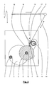
- Fig. 1 shows a partially sectioned side view of a winder 1, which serves to wind a yarn 2 on a spool 3 to a thread winding 4.
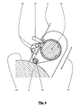
- the winding machine 1 has a turret 5 (see Fig. 2), which is formed according to the illustrated embodiment as a disc and from the opposite on the circumference two spindles 6, 7 protrude.
- the spindles 6, 7 can be offset by drive units 8, 9 independently of each other and relative to the turret 5 about their longitudinal axes in rotation.
- On the spindles 6, 7 are each sleeves 10, 11, on which the thread 2 is wound into a thread winding 4 for the purpose of forming a coil 3.
- a thread guide 12 which is mounted on a guide 13, for example a linear guide, or a plurality of guides along a degree of freedom 14 movable or displaceable.
- the thread guide 12 has a traversing device 15, over which in an angular range 16, the location of feeding the thread 2 to the thread winding 4 with respect to the longitudinal axis of the spindle 6 and the orientation of the thread to the circumferential direction in the application of the thread 2 to the filament winding. 4 is changeable.
- the thread guide 12 has in the region of the traversing device 15 upper thread guide rollers 17 which align the thread independently of the angle in the angular region 16 by specifying double-sided axial guides to an axis 36.
- lower thread guide rollers 18 are provided, which oriented parallel to the longitudinal axis of the spindle 6, according to FIG. 2 provide offset-oriented contact surfaces, for example, a fanning out of the thread 2 and / or a specification of approximately in Fig. 2 vertically oriented feed of the thread. 2 serve for the pressure roller 19.
- a pressure roller 19 whose longitudinal axis is oriented parallel to the longitudinal axis of the spindle 6. Subsequent to the lower yarn guide rollers, the yarn is guided over the partial pressure angle around the pressure roller 19. The thread is applied in the contact region of the pressure roller 19 to a lateral surface 32 of the thread winding 4.
- an actuator 20 is formed as a pneumatic actuating cylinder, which is acted upon via a pressure medium line 21.
- the actuator 20 forms a pendulum support 22.
- the pendulum support 22 is articulated in an end region 23 with respect to a housing-fixed strut 24 of the winder 1, wherein the pendulum support 22 is pivotable about an axis oriented vertically to the plane of FIG.
- the opposite end portion 37 of the pendulum support 22 is directly or indirectly on the Fadenleitmaschine Hinged 12, here adjacent to the guide 13. Compared with the degree of freedom 14, the pendulum support forms an angle ⁇ .
- the non-effective force component F H is received by the guide 13 for the illustrated embodiment.
- the change in the force ⁇ F FHG can be changed by adjustment of the basic geometry, thus changing the coupling points 33, 34 of the pendulum support 22.
- the actuator 20 extends on the side facing away from the coil 3 of the turret 5, preferably hidden by a machine base plate.
- the degree of freedom 14 may be inclined relative to the vertical. Without thereby leaving the basic principle according to the invention, it is thus possible that the angle ⁇ (deviating from the dimensioning of the angle ⁇ in FIGS. 1 and 3) is oriented in any desired spatial direction.
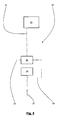
- FIG. 5 shows a pressure medium unit 26 which serves to act on the pressure medium line 21.
- the pressure medium unit 26 is supplied with a pressure medium 27 under an operating pressure.
- the pressure medium unit 26 has a control valve 28 and a pneumatic switching device 29, which is suitably controlled via a control or regulating unit 30 by means of a control line 31. Via a bypass line 35, the control valve 28 can be bypassed by the control or regulating unit 30 with appropriate wiring of the switching device 29, so that a complete lifting of the pressure roller 19 is possible.
- the control or regulating unit 30 is on the corresponding parts of EP 1 213 246 B1 directed.
- the winding machine is used in particular for the production of cheeses, for which the incoming thread travels through a traversing thread guide along the longitudinal axis of the spool.
- a traversing thread guide along the longitudinal axis of the spool.
- the angle of the traversing thread guide does not change during the winding cycle with respect to the incoming thread.
- the contact pressure of the pressure roller 19 at the thread angle 4 results from the vectorial sum of the weight of the thread guide 12 and any additional components and the force component F FHG of the actuator 20 in the direction of the degree of freedom 14.
- the degree of freedom 14 is not vertically oriented, results in a corresponding reduction in the contact force on the cos of the angle of the degree of freedom 14 with respect to the vertical.
Landscapes
- Winding Filamentary Materials (AREA)
- Replacing, Conveying, And Pick-Finding For Filamentary Materials (AREA)
Applications Claiming Priority (1)
| Application Number | Priority Date | Filing Date | Title |
|---|---|---|---|
| DE102006054980A DE102006054980B4 (de) | 2006-11-22 | 2006-11-22 | Spulmaschine |
Publications (2)
| Publication Number | Publication Date |
|---|---|
| EP1925580A1 true EP1925580A1 (fr) | 2008-05-28 |
| EP1925580B1 EP1925580B1 (fr) | 2010-08-11 |
Family
ID=39048762
Family Applications (1)
| Application Number | Title | Priority Date | Filing Date |
|---|---|---|---|
| EP07022446A Ceased EP1925580B1 (fr) | 2006-11-22 | 2007-11-20 | Bobinoir |
Country Status (5)
| Country | Link |
|---|---|
| US (1) | US20080116311A1 (fr) |
| EP (1) | EP1925580B1 (fr) |
| JP (1) | JP2008127207A (fr) |
| DE (2) | DE102006054980B4 (fr) |
| TW (1) | TWI352060B (fr) |
Cited By (1)
| Publication number | Priority date | Publication date | Assignee | Title |
|---|---|---|---|---|
| EP3626657A1 (fr) * | 2018-09-19 | 2020-03-25 | Georg Sahm GmbH & Co. KG | Bobinoir |
Families Citing this family (5)
| Publication number | Priority date | Publication date | Assignee | Title |
|---|---|---|---|---|
| DE102009026849B3 (de) | 2009-06-09 | 2011-01-13 | Georg Sahm Gmbh & Co. Kg | Spulmaschine mit einer Wechseleinrichtung und Verfahren zum Betrieb derselben |
| DE102012107015A1 (de) | 2011-08-03 | 2013-02-07 | Oerlikon Textile Gmbh & Co. Kg | Aufspulvorrichtung |
| CN203947198U (zh) * | 2014-04-22 | 2014-11-19 | 郑州中远氨纶工程技术有限公司 | 合成纤维收卷装置及纺丝位 |
| CN114772386B (zh) * | 2022-04-01 | 2023-09-01 | 沭阳金龙电子有限公司 | 一种具备纠偏功能的全自动智能绕线机 |
| CN116100158A (zh) * | 2022-12-07 | 2023-05-12 | 广州必易激光科技有限公司 | 一种用于面料的激光打标系统及方法 |
Citations (10)
| Publication number | Priority date | Publication date | Assignee | Title |
|---|---|---|---|---|
| US3672583A (en) | 1970-08-18 | 1972-06-27 | Leesona Corp | Winding apparatus and method |
| US3672584A (en) | 1970-08-27 | 1972-06-27 | Leesona Corp | Winding apparatus |
| US3845911A (en) | 1972-10-31 | 1974-11-05 | Turbo Machine Co | Winder |
| JPS5184913A (fr) * | 1975-01-24 | 1976-07-24 | Meidensha Electric Mfg Co Ltd | |
| US4009839A (en) * | 1975-10-06 | 1977-03-01 | Leesona Corporation | Winding apparatus |
| EP0160954A1 (fr) * | 1984-05-10 | 1985-11-13 | B a r m a g AG | Bobinoir |
| DE3718391A1 (de) * | 1986-06-06 | 1987-12-23 | Barmag Barmer Maschf | Kreuzspulmaschine |
| EP1213246A2 (fr) * | 2000-11-08 | 2002-06-12 | Murata Kikai Kabushiki Kaisha | Bobinoir |
| DE102005003334A1 (de) | 2004-02-19 | 2005-09-08 | Saurer Gmbh & Co. Kg | Aufspulvorrichtung |
| DE102004032514A1 (de) | 2004-07-06 | 2006-02-16 | Saurer Gmbh & Co. Kg | Spulenrahmen Be- und Entlastungsvorrichtung für eine Spuleinrichtung einer Kreuzspulen herstellenden Textilmaschine |
Family Cites Families (8)
| Publication number | Priority date | Publication date | Assignee | Title |
|---|---|---|---|---|
| JPS5468424A (en) * | 1977-11-10 | 1979-06-01 | Koutsu Seisakushiyo Kk | Yarn winder |
| JPS58158058U (ja) * | 1982-11-18 | 1983-10-21 | 株式会社神津製作所 | 巻糸機 |
| JPS638262U (fr) * | 1986-07-04 | 1988-01-20 | ||
| DE4121775A1 (de) * | 1991-07-01 | 1993-01-14 | Rieter Ingolstadt Spinnerei | Spuleinrichtung mit einer steuervorrichtung zur steuerung des auflagedruckes einer spule auf eine antriebswalze |
| DE19705262A1 (de) * | 1996-09-03 | 1998-03-05 | Barmag Barmer Maschf | Verfahren zum Aufspulen eines Fadens zu einer Spule |
| IT1319229B1 (it) * | 2000-10-20 | 2003-09-26 | Savio Macchine Tessili Spa | Dispositivo portarocche perfezionato per avvolgimento di filato conpressione regolata, particolarmente per ritorcitoi a doppia torsione. |
| DE10253489A1 (de) * | 2001-12-12 | 2003-07-03 | Barmag Barmer Maschf | Verfahren zur Steuerung einer Auflagekraft zwischen einer Andrückwalze und einem Fadenwickel |
| DE102005005096A1 (de) * | 2005-02-04 | 2006-08-10 | Saurer Gmbh & Co. Kg | Spulvorrichung für eine Kreuzspulen herstellende Textilmaschine |
-
2006
- 2006-11-22 DE DE102006054980A patent/DE102006054980B4/de not_active Expired - Fee Related
-
2007
- 2007-11-20 EP EP07022446A patent/EP1925580B1/fr not_active Ceased
- 2007-11-20 DE DE502007004708T patent/DE502007004708D1/de active Active
- 2007-11-21 US US11/943,764 patent/US20080116311A1/en not_active Abandoned
- 2007-11-22 JP JP2007303487A patent/JP2008127207A/ja active Pending
- 2007-11-22 TW TW096144246A patent/TWI352060B/zh not_active IP Right Cessation
Patent Citations (11)
| Publication number | Priority date | Publication date | Assignee | Title |
|---|---|---|---|---|
| US3672583A (en) | 1970-08-18 | 1972-06-27 | Leesona Corp | Winding apparatus and method |
| US3672584A (en) | 1970-08-27 | 1972-06-27 | Leesona Corp | Winding apparatus |
| US3845911A (en) | 1972-10-31 | 1974-11-05 | Turbo Machine Co | Winder |
| JPS5184913A (fr) * | 1975-01-24 | 1976-07-24 | Meidensha Electric Mfg Co Ltd | |
| US4009839A (en) * | 1975-10-06 | 1977-03-01 | Leesona Corporation | Winding apparatus |
| EP0160954A1 (fr) * | 1984-05-10 | 1985-11-13 | B a r m a g AG | Bobinoir |
| DE3718391A1 (de) * | 1986-06-06 | 1987-12-23 | Barmag Barmer Maschf | Kreuzspulmaschine |
| EP1213246A2 (fr) * | 2000-11-08 | 2002-06-12 | Murata Kikai Kabushiki Kaisha | Bobinoir |
| DE60116243T2 (de) | 2000-11-08 | 2007-01-11 | Murata Kikai K.K. | Aufwickelmaschine |
| DE102005003334A1 (de) | 2004-02-19 | 2005-09-08 | Saurer Gmbh & Co. Kg | Aufspulvorrichtung |
| DE102004032514A1 (de) | 2004-07-06 | 2006-02-16 | Saurer Gmbh & Co. Kg | Spulenrahmen Be- und Entlastungsvorrichtung für eine Spuleinrichtung einer Kreuzspulen herstellenden Textilmaschine |
Cited By (3)
| Publication number | Priority date | Publication date | Assignee | Title |
|---|---|---|---|---|
| EP3626657A1 (fr) * | 2018-09-19 | 2020-03-25 | Georg Sahm GmbH & Co. KG | Bobinoir |
| WO2020057875A1 (fr) | 2018-09-19 | 2020-03-26 | Georg Sahm Gmbh & Co. Kg | Bobineuse |
| US11731852B2 (en) | 2018-09-19 | 2023-08-22 | Georg Sahm Gmbh & Co. Kg | Winding machine |
Also Published As
| Publication number | Publication date |
|---|---|
| DE102006054980A1 (de) | 2008-06-05 |
| DE102006054980B4 (de) | 2008-08-14 |
| US20080116311A1 (en) | 2008-05-22 |
| TWI352060B (en) | 2011-11-11 |
| DE502007004708D1 (de) | 2010-09-23 |
| JP2008127207A (ja) | 2008-06-05 |
| TW200902422A (en) | 2009-01-16 |
| EP1925580B1 (fr) | 2010-08-11 |
Similar Documents
| Publication | Publication Date | Title |
|---|---|---|
| EP0374536B1 (fr) | Machine de bobinage | |
| DE102011052699B4 (de) | Spulmaschine und Verfahren zur Steuerung derselben | |
| EP1925580B1 (fr) | Bobinoir | |
| WO2019007729A1 (fr) | Dispositif d'enroulement doté d'un cylindre de soutien et unité de réglage de force d'appui ainsi que machine de traitement du fil | |
| DE2328828C2 (de) | Hilfsfadenführer | |
| EP0351672A1 (fr) | Dispositif pour commander la force de pression d'une bobine sur un cylindre de friction | |
| EP1765705B1 (fr) | Dispositif de chargement et de dechargement d'un bobinoir destine au dispositif de bobinage d'une machine textile a bobines croisees | |
| DE2518646A1 (de) | Vorrichtung zur steuerung des auflagedruckes einer textilspule auf eine stuetz- oder antriebswalze | |
| EP0618163B1 (fr) | Dispositif de coupe et d'application de bandes dans machines d'embobinage | |
| DE2406550C3 (fr) | ||
| EP3954638B1 (fr) | Dispositif d'enroulement | |
| DE3235789C2 (de) | Schwenkbarer Spulenhalter | |
| DE2327164A1 (de) | Spulvorrichtung zum aufspulen von textilen faeden | |
| EP1524228B1 (fr) | Dispositif de contrôle de la pression entre une bobine de textile et un rouleau de support ou d'entraînemnt | |
| EP1086916B1 (fr) | Unité de palier pour rouleaux tendeurs de bandes de matériau | |
| DE60003992T2 (de) | Vorrichtung zum Kontrollieren des Wickelns einer Wickelrolle in einer Wickelmaschine | |
| WO2006013005A1 (fr) | Dispositif de bobinage | |
| DE102010046692B4 (de) | Dockenwickler zum Wickeln einer Warenbahn zu einer Docke | |
| DE69819861T2 (de) | Vorrichtung zum Liefern eines elastisch ausdehnbaren Fadens zu Strickmaschinen | |
| WO1994014694A1 (fr) | Dispositif d'embobinage | |
| EP1414726B1 (fr) | Procede et bobineuse destines a l'enroulement continu d'une bande de materiau | |
| EP0128417B1 (fr) | Dispositif pour soulever une bobine d'enroulement | |
| DE3744600A1 (de) | Vorrichtung zum spannen und loesen einer spule | |
| DE3843202A1 (de) | Aufspulmaschine | |
| DE10352621B4 (de) | Verfahren zur seitlichen Ausrichtung einer Bahn |
Legal Events
| Date | Code | Title | Description |
|---|---|---|---|
| PUAI | Public reference made under article 153(3) epc to a published international application that has entered the european phase |
Free format text: ORIGINAL CODE: 0009012 |
|
| AK | Designated contracting states |
Kind code of ref document: A1 Designated state(s): AT BE BG CH CY CZ DE DK EE ES FI FR GB GR HU IE IS IT LI LT LU LV MC MT NL PL PT RO SE SI SK TR |
|
| AX | Request for extension of the european patent |
Extension state: AL BA HR MK RS |
|
| 17P | Request for examination filed |
Effective date: 20080709 |
|
| 17Q | First examination report despatched |
Effective date: 20080922 |
|
| AKX | Designation fees paid |
Designated state(s): CZ DE HU RO |
|
| GRAP | Despatch of communication of intention to grant a patent |
Free format text: ORIGINAL CODE: EPIDOSNIGR1 |
|
| GRAS | Grant fee paid |
Free format text: ORIGINAL CODE: EPIDOSNIGR3 |
|
| GRAA | (expected) grant |
Free format text: ORIGINAL CODE: 0009210 |
|
| AK | Designated contracting states |
Kind code of ref document: B1 Designated state(s): CZ DE HU RO |
|
| REF | Corresponds to: |
Ref document number: 502007004708 Country of ref document: DE Date of ref document: 20100923 Kind code of ref document: P |
|
| REG | Reference to a national code |
Ref country code: RO Ref legal event code: EPE |
|
| REG | Reference to a national code |
Ref country code: HU Ref legal event code: AG4A Ref document number: E009453 Country of ref document: HU |
|
| PLBE | No opposition filed within time limit |
Free format text: ORIGINAL CODE: 0009261 |
|
| STAA | Information on the status of an ep patent application or granted ep patent |
Free format text: STATUS: NO OPPOSITION FILED WITHIN TIME LIMIT |
|
| 26N | No opposition filed |
Effective date: 20110512 |
|
| REG | Reference to a national code |
Ref country code: DE Ref legal event code: R097 Ref document number: 502007004708 Country of ref document: DE Effective date: 20110512 |
|
| PGFP | Annual fee paid to national office [announced via postgrant information from national office to epo] |
Ref country code: CZ Payment date: 20181106 Year of fee payment: 12 Ref country code: DE Payment date: 20181010 Year of fee payment: 12 Ref country code: RO Payment date: 20181108 Year of fee payment: 12 Ref country code: HU Payment date: 20181031 Year of fee payment: 12 |
|
| REG | Reference to a national code |
Ref country code: DE Ref legal event code: R119 Ref document number: 502007004708 Country of ref document: DE |
|
| PG25 | Lapsed in a contracting state [announced via postgrant information from national office to epo] |
Ref country code: RO Free format text: LAPSE BECAUSE OF NON-PAYMENT OF DUE FEES Effective date: 20191120 Ref country code: CZ Free format text: LAPSE BECAUSE OF NON-PAYMENT OF DUE FEES Effective date: 20191120 |
|
| PG25 | Lapsed in a contracting state [announced via postgrant information from national office to epo] |
Ref country code: HU Free format text: LAPSE BECAUSE OF NON-PAYMENT OF DUE FEES Effective date: 20191121 |
|
| PG25 | Lapsed in a contracting state [announced via postgrant information from national office to epo] |
Ref country code: DE Free format text: LAPSE BECAUSE OF NON-PAYMENT OF DUE FEES Effective date: 20200603 |