EP0160954A1 - Bobinoir - Google Patents
Bobinoir Download PDFInfo
- Publication number
- EP0160954A1 EP0160954A1 EP85105473A EP85105473A EP0160954A1 EP 0160954 A1 EP0160954 A1 EP 0160954A1 EP 85105473 A EP85105473 A EP 85105473A EP 85105473 A EP85105473 A EP 85105473A EP 0160954 A1 EP0160954 A1 EP 0160954A1
- Authority
- EP
- European Patent Office
- Prior art keywords
- lever
- winding machine
- machine according
- support arm
- carriage
- Prior art date
- Legal status (The legal status is an assumption and is not a legal conclusion. Google has not performed a legal analysis and makes no representation as to the accuracy of the status listed.)
- Granted
Links
- 238000004804 winding Methods 0.000 title claims abstract description 42
- 239000000835 fiber Substances 0.000 claims abstract description 3
- 230000005484 gravity Effects 0.000 claims description 5
- 238000005452 bending Methods 0.000 abstract description 4
- 230000005540 biological transmission Effects 0.000 description 2
- 230000002349 favourable effect Effects 0.000 description 2
- 238000004519 manufacturing process Methods 0.000 description 1
- 239000000463 material Substances 0.000 description 1
- 230000010355 oscillation Effects 0.000 description 1
- 238000009987 spinning Methods 0.000 description 1
Images


Classifications
-
- B—PERFORMING OPERATIONS; TRANSPORTING
- B65—CONVEYING; PACKING; STORING; HANDLING THIN OR FILAMENTARY MATERIAL
- B65H—HANDLING THIN OR FILAMENTARY MATERIAL, e.g. SHEETS, WEBS, CABLES
- B65H54/00—Winding, coiling, or depositing filamentary material
- B65H54/02—Winding and traversing material on to reels, bobbins, tubes, or like package cores or formers
- B65H54/40—Arrangements for rotating packages
- B65H54/52—Drive contact pressure control, e.g. pressing arrangements
-
- B—PERFORMING OPERATIONS; TRANSPORTING
- B65—CONVEYING; PACKING; STORING; HANDLING THIN OR FILAMENTARY MATERIAL
- B65H—HANDLING THIN OR FILAMENTARY MATERIAL, e.g. SHEETS, WEBS, CABLES
- B65H2701/00—Handled material; Storage means
- B65H2701/30—Handled filamentary material
- B65H2701/31—Textiles threads or artificial strands of filaments
Definitions
- the invention relates to a winding machine for man-made fibers. It is used in particular for winding freshly spun and / or drawn multifilament threads in spinning machines.
- the winding machine has a traversing device and a winding spindle.
- the traversing device and the winding spindle are movably mounted relative to one another, e.g. the winding spindle is fixed in a frame and the traversing device is mounted in a movable carriage.
- Such a winding machine is shown in DE-OS 20 39 772, in which the traversing mechanism is mounted in a structural unit consisting of a slide and a cantilever arm attached to it.
- the carriage is essentially straight in a straight guide and is guided such that the traversing device can avoid the growing diameter of the bobbin formed on the bobbin.
- the weight of the unit consisting of the slide and the support arm is compensated for in whole or in part by a force transmitter which is designed as a pneumatic cylinder-piston unit in the known winding machine.
- the solution according to the invention is characterized in that the force transmitter does not act directly on the carriage, but rather by means of a one-armed or two-armed lever articulated in the frame of the winding machine in the central region of the support arm, preferably in the longitudinal center of gravity of the support arm. It is hereby avoided that the support arm and slide exert an impermissible bending moment on the guides and are themselves subjected to an impermissible bending moment.
- lever transmission ratio can be chosen so that despite a large range of movement of the slide, the support arm and the traversing, i.e. Despite the production of coils with a very large diameter, the length of movement of the force transmitter can be chosen to be smaller in the ratio of the lever transmission ratio, which is favorable for friction, wear and space utilization.
- the force transmitter preferably engages between the pivot point and the Longitudinal center of the pivot lever, while the end of the pivot lever rests on the support arm.
- the force transmitter engages at one end, while the other end rests on the support arm.
- the lever is designed with two arms and bent at its pivot point, so that despite the limited length of the frame of the winding machine, a sufficient length of the lever arm is provided for the force application of the force transmitter.
- the force transmitter used in the context of this invention is preferably a hydraulic or pneumatic cylinder-piston unit. This cylinder-piston unit is applied to a constant or variable pressure in the course of the winding cycle. As a result, part of the weight of the assembly consisting of slide, support arm, traversing, etc. is absorbed. It can thus be achieved that a drive roller, which is also mounted in the support arm, bears against the bobbins to be formed on the bobbin spindle with only a certain, predetermined pressure which may be variable in the course of the winding cycle.
- the guide used within the scope of this invention is a straight guide, e.g. in the form of a cylinder-roller guide, which is arranged in a fixed position in the frame and on which the slide slides.
- An embodiment with a particularly high stability of the assembly arm and carriage is achieved in that the assembly is guided in a straight line by two guides which are arranged at the ends of a diagonal of the carriage. This gives the guides their greatest possible distance.
- the point of engagement of the lever with respect to the support arm has a degree of freedom in the longitudinal direction.
- the free end and the support arm can lie on one another in a plain bearing.
- the support arm and the lever are connected by an intermediate lever which is articulated on the support arm on the one hand and on the lever on the other hand.
- the point of application of the lever is articulated to the support arm and that the lever itself is mounted with a degree of freedom in relation to its frame.
- the swivel joint of the lever can be mounted in a slide bearing.
- the force transmitter has a degree of freedom transverse to its direction of force relative to the lever.
- the power transmitter is pivotally mounted or the power transmitter and the lever are connected to one another by a hinged intermediate lever.
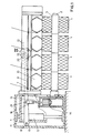
- the winding spindle 2 is mounted in a stationary and freely rotatable manner in the fixed frame 1.
- Sleeves 3 are attached to the winding spindle.
- a coil 4 is formed on each sleeve 3.
- the coils with the winding spindle are driven by the drive roller 5 (see FIG. 3).
- Changings 6 are used to move the threads back and forth.
- Each oscillation 6 consists of a thread guide 7, which is driven in a straight guide 8 by a reversing thread shaft 9, and of a grooved roller 10 therein recessed grooves (see. Fig. 3).
- any other traversing can be used, such as a so-called "wing traversing”.
- the drive roller and the traversing mechanism are mounted in a slide 11 and a support arm 12 attached thereto, the support arm 12 being attached to the slide 11 in a cantilever manner.
- the carriage 11 is movable in two straight guides 13 in the vertical direction. This ensures that the traversing and the drive roller can avoid the growing spool diameter.
- a force transmitter 14 is provided, in the illustrated case a cylinder-piston unit, as also by the prior art is known.
- the piston rod 15 engages via an intermediate lever 16 on a lever 17 which is mounted on one side on the frame 1 in the pivot point 18 and engages with its free end 19 on a slide bearing 20 of the support arm 12.
- the distance between the pivot point and the point 21 of the force application of the force transmitter 14 on the one hand and the end 19 of the support arm on the other hand is selected so that the slide or support arm at the predetermined stroke length of the force transmitter the stroke sufficient for the desired maximum coil diameter, which also allows the drive roller to be lifted off the spool surfaces.
- the slide bearing 20 is attached approximately in the longitudinal center of the support arm and approximately in the longitudinal center of gravity of the entire structural unit comprising the slide 11 and the support arm 12. It is not necessary for this longitudinal center of gravity to be adhered to exactly, since it can be assumed that the guides 13 will be able to do so anyway need to catch a certain moment. However, this design prevents the support arm from exerting an impermissibly high bending moment on the slide 11 and the guides 13.
- the slide bearing 20 serves to ensure the degree of freedom in the longitudinal direction of the support arm 12 required for the lever end 19 when the lever is pivoted about pivot bearing 18.
- Fig. 4 shows an alternative to the sliding bearing 20 that the end 19 is connected to the support arm 12 by an intermediate lever 22.
- the intermediate lever is articulated on the support arm 12 on the one hand and the end 19 of the lever 17 on the other hand and permits relative movement in the longitudinal direction of the support arm.
- the winding spindle 2 with the sleeves 3 and coils 4 mounted thereon is rotatably mounted in the stationary frame 1 and driven by the drive roller 5.
- the thread guide 7 is moved back and forth in the straight guide 8 by a reversing thread shaft 9. Downstream of the thread guide 7 in the thread run is the grooved roller 10, through which the thread is laid on the spool.
- the traversing 6 with the reverse thread shaft 9 and the thread guide 7 and the grooved roller 10 and the drives, not shown, and also the driving roller 5 with its drive, not shown, are mounted in the carriage 11.
- the carriage 11 has the support arm 12 for receiving the bearings, which extends along the winding spindle.
- the carriage is movable in the straight guides 13.
- the straight guides 13 consist of stamps 23 on the one hand and bushes 24 on the other hand.
- the stamps 23 are fastened in the frame 1.
- the bushings 24 slide as free of play and friction as possible - for example via embedded rollers or balls on the punches 23.
- Two guides - as can be seen in FIG. 5 - are provided at the end points of the diagonal of the slide 11, thereby ensuring stable guidance of the slide Support arm 12 is made possible.
- the vertical movement of the slide and support arm 12 is brought about by the lever 17, which engages with its end 19 on the slide guide 20 of the support arm 12. It is mounted laterally from the carriage 11 - as shown in FIG. 3 - in a pivot bearing 18 on the frame.
- the slide bearing 20 is designed as a slot-shaped hole 28 in the longitudinal direction, in which hole a laterally projecting pin 27 of the lever 17 engages.
- the other end of the two-armed lever 17 in this embodiment is bent vertically.
- the force transmitter 14 engages in the force application point 21.
- the force transmitter 14 is pivotably mounted in the pivot point 25 in order to take into account the mobility of the force application point 21 when the lever 17 is pivoted.
- Fig. ' 5 shows that the piston rod 15 is articulated at the point 21 of the lever 17 by the U-shaped yoke 26.
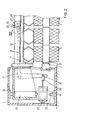
- FIG. 6 shows an embodiment similar to FIG. 2, in which the winding spindle 2 with the sleeves 3 and coils 4 mounted thereon is rotatably mounted in the fixed frame 1 and is driven by the drive roller 5.
- the thread guide 7 is moved back and forth in the straight guide 8 by a reversing thread shaft 9. Downstream of the thread guide 7 is the grooved roller 10, through which the thread is laid on the spool becomes.
- the traversing 6 with the reverse thread shaft 9 and the thread guide 7 and the grooved roller 10 and the drives, not shown, and also the driving roller 5 with its drive, not shown, is mounted in the carriage 11.
- the carriage 11 has the support arm 12 for receiving the bearings, which extends along the winding spindle.
- the carriage is movable in the straight guides 13.
- the straight guides 13 consist on the one hand of punches 23 and on the other hand of bushings 24.
- the punches 23 are fastened in the frame 1.
- the bushings 24 slide as free of play and friction as possible - for example via embedded rollers or balls on the punches 23.
- Two guides - as can be seen in FIG. 5 - are provided at the end points of the diagonal of the slide 11, thereby ensuring stable guidance of the slide Support arm 12 is made possible.
- the vertical movement of the carriage and support arm 12 is brought about by the lever 17, which engages with its end 19 on the support arm 12 in a fixed joint 29.
- the lever 17 is mounted on the side of the carriage 11 - just as in FIG. 3 - in a pivot bearing 18.
- This pivot bearing 18 is seated at the end of an intermediate lever 30.
- the intermediate lever 30 is articulated in the frame 31 in articulation 31.
- the joints 18 and 30 lie at least approximately on the resultant of the support force in the joint 29 and the application force of the force transmitter 14 in the application point 21.
- the other end of the lever 17, which in this exemplary embodiment is also two-armed, is bent vertically.
- the force transmitter 14 engages in the force application point 21.
- the force transmitter 14 is pivotably mounted in the pivot point 25 in order to take into account the mobility of the force application point 21 when the lever 17 is pivoted.
Landscapes
- Winding Filamentary Materials (AREA)
- Warping, Beaming, Or Leasing (AREA)
- Preliminary Treatment Of Fibers (AREA)
Applications Claiming Priority (4)
| Application Number | Priority Date | Filing Date | Title |
|---|---|---|---|
| DE19843417258 DE3417258A1 (de) | 1984-05-10 | 1984-05-10 | Aufspulmaschine |
| DE3417258 | 1984-05-10 | ||
| DE3446444 | 1984-12-20 | ||
| DE3446444 | 1984-12-20 |
Publications (2)
| Publication Number | Publication Date |
|---|---|
| EP0160954A1 true EP0160954A1 (fr) | 1985-11-13 |
| EP0160954B1 EP0160954B1 (fr) | 1987-03-11 |
Family
ID=25821070
Family Applications (1)
| Application Number | Title | Priority Date | Filing Date |
|---|---|---|---|
| EP85105473A Expired EP0160954B1 (fr) | 1984-05-10 | 1985-05-04 | Bobinoir |
Country Status (5)
| Country | Link |
|---|---|
| US (1) | US4613089A (fr) |
| EP (1) | EP0160954B1 (fr) |
| JP (1) | JPS6118679A (fr) |
| CN (1) | CN1003015B (fr) |
| DE (1) | DE3560088D1 (fr) |
Cited By (5)
| Publication number | Priority date | Publication date | Assignee | Title |
|---|---|---|---|---|
| EP0367726A1 (fr) * | 1988-11-04 | 1990-05-09 | Maschinenfabrik Rieter Ag | Dispositif de compensation de l'affaissement de la broche de bobinage dans une machine à bobiner |
| EP0371912A1 (fr) * | 1988-11-28 | 1990-06-06 | Maschinenfabrik Rieter Ag | Dispositif pour la commande de pression |
| EP0618165A3 (fr) * | 1993-03-15 | 1995-02-15 | Toray Eng Co Ltd | Procédé pour contrÔler l'entraînement d'une machine à bobiner du fil textile, et enrouleur de fil utilisant ce procédé. |
| US5762276A (en) * | 1992-10-05 | 1998-06-09 | Toray Engineering Co., Ltd. | Yarn winding roller drive |
| EP1925580A1 (fr) * | 2006-11-22 | 2008-05-28 | Georg Sahm Gmbh & Co. Kg | Bobinoir |
Families Citing this family (8)
| Publication number | Priority date | Publication date | Assignee | Title |
|---|---|---|---|---|
| JP2505140B2 (ja) * | 1991-12-05 | 1996-06-05 | 村田機械株式会社 | 紡糸巻取機 |
| JP3224928B2 (ja) * | 1993-01-14 | 2001-11-05 | 帝人製機株式会社 | 糸条の巻取機 |
| CN101628672B (zh) * | 2008-07-14 | 2012-07-18 | 浙江日发纺织机械股份有限公司 | 槽筒络并机防重叠方法及装置 |
| CN102963746B (zh) * | 2012-12-11 | 2015-06-10 | 佳源机电工业(昆山)有限公司 | 废料卷取机 |
| CN104444575A (zh) * | 2014-11-03 | 2015-03-25 | 洪恒丰 | 一种便于加载线筒且可自动张紧的纺织绕线机 |
| CN104401799B (zh) * | 2014-11-03 | 2016-06-15 | 重庆晨宇机床制造有限公司 | 一种便于加载线筒的固定式纺织绕线机 |
| CN104401809B (zh) * | 2014-11-03 | 2015-07-29 | 江苏银桥纺织科技有限公司 | 一种便于加载线筒的纺织绕线机及其操作方法 |
| CN104973451B (zh) * | 2015-06-18 | 2017-12-12 | 中民循环经济产业技术开发(山东)有限公司 | 一种收纱装置 |
Citations (4)
| Publication number | Priority date | Publication date | Assignee | Title |
|---|---|---|---|---|
| FR2104203A5 (en) * | 1970-08-11 | 1972-04-14 | Barmag Barmer Maschf | Bobbin winding equipment - with friction drive and controlled contact pressure |
| US4006863A (en) * | 1975-10-06 | 1977-02-08 | Leesona Corporation | Strand scattering winding machine |
| FR2329575A1 (fr) * | 1975-10-30 | 1977-05-27 | Mitsubishi Heavy Ind Ltd | Bobinoir a grande vitesse avec montage perfectionne du cylindre d'entrainement et procede de bobinage |
| DE2626504A1 (de) * | 1974-01-24 | 1977-12-29 | Schlafhorst & Co W | Aufwickeleinrichtung fuer konische kreuzspulen |
Family Cites Families (3)
| Publication number | Priority date | Publication date | Assignee | Title |
|---|---|---|---|---|
| DE1902528A1 (de) * | 1969-01-18 | 1970-09-03 | Glanzstoff Ag | Aufwickelvorrichtung |
| DE7121710U (de) * | 1971-06-04 | 1971-10-07 | Barmag Ag | Spulvorrichtung mit Treibwalzenantrieb |
| US3807647A (en) * | 1972-06-15 | 1974-04-30 | Karlsruhe Augsburg Iweka | Yarn take-up arrangement |
-
1985
- 1985-05-04 DE DE8585105473T patent/DE3560088D1/de not_active Expired
- 1985-05-04 EP EP85105473A patent/EP0160954B1/fr not_active Expired
- 1985-05-08 CN CN85103902A patent/CN1003015B/zh not_active Expired
- 1985-05-09 US US06/732,508 patent/US4613089A/en not_active Expired - Fee Related
- 1985-05-10 JP JP60098186A patent/JPS6118679A/ja active Pending
Patent Citations (4)
| Publication number | Priority date | Publication date | Assignee | Title |
|---|---|---|---|---|
| FR2104203A5 (en) * | 1970-08-11 | 1972-04-14 | Barmag Barmer Maschf | Bobbin winding equipment - with friction drive and controlled contact pressure |
| DE2626504A1 (de) * | 1974-01-24 | 1977-12-29 | Schlafhorst & Co W | Aufwickeleinrichtung fuer konische kreuzspulen |
| US4006863A (en) * | 1975-10-06 | 1977-02-08 | Leesona Corporation | Strand scattering winding machine |
| FR2329575A1 (fr) * | 1975-10-30 | 1977-05-27 | Mitsubishi Heavy Ind Ltd | Bobinoir a grande vitesse avec montage perfectionne du cylindre d'entrainement et procede de bobinage |
Cited By (7)
| Publication number | Priority date | Publication date | Assignee | Title |
|---|---|---|---|---|
| EP0367726A1 (fr) * | 1988-11-04 | 1990-05-09 | Maschinenfabrik Rieter Ag | Dispositif de compensation de l'affaissement de la broche de bobinage dans une machine à bobiner |
| EP0371912A1 (fr) * | 1988-11-28 | 1990-06-06 | Maschinenfabrik Rieter Ag | Dispositif pour la commande de pression |
| US5762276A (en) * | 1992-10-05 | 1998-06-09 | Toray Engineering Co., Ltd. | Yarn winding roller drive |
| EP0618165A3 (fr) * | 1993-03-15 | 1995-02-15 | Toray Eng Co Ltd | Procédé pour contrÔler l'entraînement d'une machine à bobiner du fil textile, et enrouleur de fil utilisant ce procédé. |
| US5605294A (en) * | 1993-03-15 | 1997-02-25 | Toray Engineering Co., Ltd. | Method for controlling the drive of a yarn winder, and the yarn winder thereof |
| US5934601A (en) * | 1993-03-15 | 1999-08-10 | Toray Engineering Co., Ltd. | Method for controlling the drive of a yarn winder, and the yarn winder thereof |
| EP1925580A1 (fr) * | 2006-11-22 | 2008-05-28 | Georg Sahm Gmbh & Co. Kg | Bobinoir |
Also Published As
| Publication number | Publication date |
|---|---|
| EP0160954B1 (fr) | 1987-03-11 |
| CN1003015B (zh) | 1989-01-04 |
| DE3560088D1 (en) | 1987-04-16 |
| US4613089A (en) | 1986-09-23 |
| JPS6118679A (ja) | 1986-01-27 |
| CN85103902A (zh) | 1986-07-09 |
Similar Documents
| Publication | Publication Date | Title |
|---|---|---|
| DE3823042A1 (de) | Koordinatenmessgeraet | |
| EP0160954B1 (fr) | Bobinoir | |
| DE3209164A1 (de) | Drahtsaege | |
| DE1916580A1 (de) | Aufwickelvorrichtung | |
| DE112007001233B4 (de) | Verfahren und Vorrichtung zur Garnchangierung bei der Aufwicklung des Garns auf eine Spule | |
| DE2518646C2 (de) | Vorrichtung zur Steuerung des Auflagedruckes einer Textilspule auf eine Stütz- oder Antriebswalze | |
| DE2547401C2 (de) | Spulvorrichtung zum Aufwickeln von Fäden auf Spulenhülsen | |
| LU102827B1 (de) | Fadenspeichereinheit für eine Arbeitsstelle einer Textilmaschine | |
| EP3571148B1 (fr) | Bobineuse | |
| WO1981000248A1 (fr) | Dispositif de bobinage pour fils | |
| DE2649555C3 (de) | Friktionsantriebsvorrichtung | |
| DE2328993B1 (de) | Aufspuleinrichtung | |
| DE4235203A1 (de) | Spinnereivorrichtung | |
| DE2454900C3 (fr) | ||
| DE69915860T2 (de) | Anordnung zum aufwickeln von kabel oder dergleichen | |
| DE2246764A1 (de) | Aufwindvorrichtung mit automatischem spulenwechsel mit mitteln zur kompensation der fadenspannungsschwankungen beim wechseln der spulen | |
| DE2144363A1 (de) | Wartungsvorrichtung für Spinn- oder Zwirnmaschine | |
| EP0012937B1 (fr) | Dispositif de va-et-vient pour bobinoir avec amplitude variable et ajustement collectif et régulier de l'angle des flancs des paquets de fil | |
| DE29608167U1 (de) | Zentralverstelleinrichtung für Fadenklemmen von Spulengattern | |
| EP0141258B1 (fr) | Dispositif de bobinage pour la formation d'enroulement d'ouate | |
| DE20302374U1 (de) | Scherenhubtisch | |
| DE3417258A1 (de) | Aufspulmaschine | |
| DE60118964T2 (de) | Vorrichtung und verfahren zum wickeln von bahnen | |
| DE20307581U1 (de) | Wickelmaschine zum kontinuierlichen Aufwickeln einer laufenden Materialbahn | |
| DE3734481C2 (fr) |
Legal Events
| Date | Code | Title | Description |
|---|---|---|---|
| PUAI | Public reference made under article 153(3) epc to a published international application that has entered the european phase |
Free format text: ORIGINAL CODE: 0009012 |
|
| AK | Designated contracting states |
Designated state(s): CH DE FR GB IT LI |
|
| 17P | Request for examination filed |
Effective date: 19851010 |
|
| 17Q | First examination report despatched |
Effective date: 19860509 |
|
| ITF | It: translation for a ep patent filed | ||
| GRAA | (expected) grant |
Free format text: ORIGINAL CODE: 0009210 |
|
| RAP1 | Party data changed (applicant data changed or rights of an application transferred) |
Owner name: B A R M A G AG |
|
| AK | Designated contracting states |
Kind code of ref document: B1 Designated state(s): CH DE FR GB IT LI |
|
| REF | Corresponds to: |
Ref document number: 3560088 Country of ref document: DE Date of ref document: 19870416 |
|
| ET | Fr: translation filed | ||
| PLBE | No opposition filed within time limit |
Free format text: ORIGINAL CODE: 0009261 |
|
| STAA | Information on the status of an ep patent application or granted ep patent |
Free format text: STATUS: NO OPPOSITION FILED WITHIN TIME LIMIT |
|
| 26N | No opposition filed | ||
| PGFP | Annual fee paid to national office [announced via postgrant information from national office to epo] |
Ref country code: GB Payment date: 19900420 Year of fee payment: 6 Ref country code: FR Payment date: 19900420 Year of fee payment: 6 |
|
| PGFP | Annual fee paid to national office [announced via postgrant information from national office to epo] |
Ref country code: CH Payment date: 19900517 Year of fee payment: 6 |
|
| PGFP | Annual fee paid to national office [announced via postgrant information from national office to epo] |
Ref country code: DE Payment date: 19900525 Year of fee payment: 6 |
|
| ITTA | It: last paid annual fee | ||
| PG25 | Lapsed in a contracting state [announced via postgrant information from national office to epo] |
Ref country code: GB Effective date: 19910504 |
|
| PG25 | Lapsed in a contracting state [announced via postgrant information from national office to epo] |
Ref country code: LI Effective date: 19910531 Ref country code: CH Effective date: 19910531 |
|
| GBPC | Gb: european patent ceased through non-payment of renewal fee | ||
| PG25 | Lapsed in a contracting state [announced via postgrant information from national office to epo] |
Ref country code: FR Effective date: 19920131 |
|
| REG | Reference to a national code |
Ref country code: CH Ref legal event code: PL |
|
| PG25 | Lapsed in a contracting state [announced via postgrant information from national office to epo] |
Ref country code: DE Effective date: 19920303 |
|
| REG | Reference to a national code |
Ref country code: FR Ref legal event code: ST |