EP1925700A1 - Dispositif d'aide à la création de patrons d'un métier à tricoter à mailles jetées - Google Patents
Dispositif d'aide à la création de patrons d'un métier à tricoter à mailles jetées Download PDFInfo
- Publication number
- EP1925700A1 EP1925700A1 EP07016979A EP07016979A EP1925700A1 EP 1925700 A1 EP1925700 A1 EP 1925700A1 EP 07016979 A EP07016979 A EP 07016979A EP 07016979 A EP07016979 A EP 07016979A EP 1925700 A1 EP1925700 A1 EP 1925700A1
- Authority
- EP
- European Patent Office
- Prior art keywords
- clamping
- thread
- pattern
- pattern thread
- abstreifklemmplatine
- Prior art date
- Legal status (The legal status is an assumption and is not a legal conclusion. Google has not performed a legal analysis and makes no representation as to the accuracy of the status listed.)
- Withdrawn
Links
Images
Classifications
-
- D—TEXTILES; PAPER
- D04—BRAIDING; LACE-MAKING; KNITTING; TRIMMINGS; NON-WOVEN FABRICS
- D04B—KNITTING
- D04B23/00—Flat warp knitting machines
- D04B23/22—Flat warp knitting machines with special thread-guiding means
-
- D—TEXTILES; PAPER
- D04—BRAIDING; LACE-MAKING; KNITTING; TRIMMINGS; NON-WOVEN FABRICS
- D04B—KNITTING
- D04B27/00—Details of, or auxiliary devices incorporated in, warp knitting machines, restricted to machines of this kind
- D04B27/10—Devices for supplying, feeding, or guiding threads to needles
- D04B27/24—Thread guide bar assemblies
- D04B27/32—Thread guide bar assemblies with independently-movable thread guides controlled by Jacquard mechanisms
-
- D—TEXTILES; PAPER
- D04—BRAIDING; LACE-MAKING; KNITTING; TRIMMINGS; NON-WOVEN FABRICS
- D04B—KNITTING
- D04B27/00—Details of, or auxiliary devices incorporated in, warp knitting machines, restricted to machines of this kind
Definitions
- the invention relates to a patterning auxiliary device of a warp knitting machine with a pattern thread engageable thread gripping device and a clamping device for holding the pattern thread.
- Such a patterning auxiliary device in a warp knitting machine is for example out DE 195 14 995 C2 known.
- the thread-grasping device has a selection hook that can be moved into the threadline of a pattern thread to grip the pattern thread.
- the selection hook is then withdrawn together with the detected pattern thread and then clamps the thread between itself and a hook guide.
- the pattern thread is then severed in the vicinity of the selection hook, so that it is not further integrated into the fabric base of a knitted fabric. This makes it possible, for example, to create a pattern with pattern figures that are in production direction the knitted fabric are arranged separately from each other.
- the invention has for its object to expand pattern options.
- This object is achieved in a patterning auxiliary device of the type mentioned above in that the thread-grasping device and the clamping device are separated from each other.
- the thread-gripping device can still detect a pattern thread to take it out of the pattern process.
- the clamping means is formed separately from the thread-grasping means, which is usually effected by being separated from each other, the thread-grasping means can be used to insert the pattern thread into the clamping means.
- the thread-grasping device can be released from the pattern thread in a simple manner, without it being necessary to cut through the pattern thread here.
- the clamped pattern thread can then be pulled out of the clamping device during the further active process without it having to be severed.
- This provides extended patterning possibilities. Namely you can the pattern thread between two binding sites, where he in the goods reason is bound, extend, so that the pattern thread floats in this area, but no longer rests on the ground. This can either be exploited to create a different visual appearance, or one can use this lapping to separate the floating pattern thread at both ends. This is easier than with a floating pattern thread that rests against the ground, because you can easily lift the floating longer pattern thread from the ground to cut through it.
- this embodiment has the advantage that you can solve the selection hook after a machine revolution again from the pattern thread so that it can be used to grasp another pattern thread or another portion of the pattern thread. This provides further possibilities for patterning.
- the thread-gripping device is designed as a hook, which is movable for releasing the pattern thread to the clamping device.
- the hook forms a loop of the pattern thread, which, when the pattern thread is clamped in the clamping device, can be made tension-free. From a tension-free loop, the hook can be relatively easily removed.
- the pattern thread can be solved under the train of progressing knitted fabric from the clamping device, so that the respectively selected pattern thread is available with an increased length between two binding sites.
- the clamping device can certainly hold several loops at the same time in stock, the loops due to the progression not all have the same size of the knitting process.
- the patterning auxiliary machine has a plurality of such clamping devices and thread gripping devices which are distributed over the working width of the warp knitting machine, so that in principle for each pattern thread a corresponding pattern control can be given.
- the clamping device is associated with a counter holder.
- the anvil ensures that the pattern thread can always be drawn into the clamping device with a predetermined orientation.
- the anvil is also a kind of reference point for the hook to release the hook from the loop formed by the clamped pattern thread.
- the counter-holder is formed as a wire, which is associated with a plurality of juxtaposed clamping devices. In the simplest case you can pass this wire over the entire working width of the warp knitting machine.
- the clamping device has an alley with an opening and a nip.
- the alley has a width that is greater than the thickness of the pattern thread. It is therefore relatively easy to introduce the pattern thread in the alley. If the pattern thread is then moved further into the alley, then it reaches the nip where it is held.
- the clamping point has at least one elastically deformable boundary.
- the limitation is achieved for holding the pattern thread necessary clamping force.
- the pattern thread is spared by this design. He is only slightly deformed himself.
- the nip is formed linear. This does not mean a line in the mathematically exact sense.
- the pattern thread is held along a line. This makes it possible to set the clamping force acting on the pattern thread, relatively accurate.
- the linear nip is also capable of holding multiple sections of a pattern thread or multiple pattern threads simultaneously.
- the nip is limited by a clamp body.
- a clamp body may be formed, for example, as a cylinder.
- the use of a clamping body facilitates the production of the patterning auxiliary device.
- the choice of the shape of the clamp body gives the designer a certain freedom in the design of the clamping forces.
- the clamping body is arranged on a holder which is arranged between two lanes, wherein the clamping body projects into both lanes. So you use a single clamp body for two lanes, so that a clamp body can hold pattern threads in two lanes, if desired.
- the nip can also be limited by a bristle element.
- a bristle element also generates the necessary holding force on the pattern thread.
- a chamber is formed behind the nip.
- This chamber can accommodate pattern threads, which are pushed by the clamping operation of subsequent pattern threads or pattern thread sections from the clamping area on. This can easily hold several threads or sections of thread at one time in the clamping device, but at the same time ensure that these threads are not confused with each other.
- the nip is formed by two plates which bear against each other in a clamping region or at a distance from each other which is smaller than the thickness of the pattern thread.
- the clamping area is formed flat.
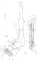
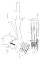
- the stripper clamping plate 1 is used to hold selected pattern threads 2 and to release them after a brief hold.
- Abstreifklemmplatinen 1 are held in a socket or Barre 3.
- the Abstreifklemmplatinen 1 are distributed over the working width of the warp knitting machine and preferably maintained at the distance of the machine fineness. This makes it possible to select each of the pattern threads 2.
- the Abstreifklemmplatine works with a selection hook 4 together, with the pattern thread 2 can be brought into engagement.
- the selection hook 4 is moved from the position shown in Fig. 1a, first relative to the Abstreifklemmplatine 1 vertically upwards and then to the left, so that it enters the course of the corresponding pattern thread 2.
- the pattern thread 2 is then moved by a corresponding movement of the pattern guide bar in over or underlay so that it comes to rest over the selection hook 4.
- the selection hook 4 is then again moved to the right and down, so that it assumes the position shown in Fig. 1a.
- the selection hook 4 has taken the pattern thread 2 and the selection hook 4 has been moved to the position shown in FIG. 1, then the pattern thread 2 is pulled over a counter-holder designed as a wire 5 and simultaneously clamped in a clamping region 6. About the anvil 5 then forms a loop 7, which can be made dead, so that the selection hook 4 can be solved by a movement to the left, so the clamping area 6 out of the loop 7 of the pattern thread 2. Although the pattern thread 2 is then still clamped in the clamping region 6, the selection hook 4 can already be used again to take the pattern thread 2 at another location or another pattern thread, which is guided at the same or an adjacent position and to select.
- the pattern thread 2 is no longer held by the selection hook 4, it can be pulled out of the clamping area 6. Since the pattern thread 2 is still integrated into the fabric base of the knitted fabric, a corresponding tensile force is exerted on the pattern thread 2 by the further movement of the knitted fabric, which pulls the pattern thread 2 from the clamping region 6.
- FIGS. 1b and 1c now show the formation of the clamping region, FIG. 1b being a section b-b according to FIG. 1a and FIG. 1c being a plan view of two wiper clamping plates.
- Each Abstreifklemmplatine 1 has a lane 8 with an opening 9 which is so wide that the selection hook 4 can easily insert the pattern thread 2 in the alley 8.
- the clamping point 6 is formed by a resilient plate 10 which cooperates with a side wall 11 of an adjacent Abstreifklemmplatine.
- the resilient plate 10 has a sliding surface 12, on which the pattern thread 2 slides into the clamping region 6. When the pattern thread 2 is then drawn between the resilient plate 10 and the wall 11, it is held by frictional force, i. it can be pulled out of the clamping area 6 again by applying a tensile force.
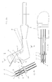
- FIG. 2a shows a modified embodiment, wherein the same elements with the same reference numerals as in Fig. 1a-1c are designated.
- Fig. 2b is a sectional view taken along the line b-b of Fig. 2a.
- FIG. 2 c is a top view of the wiper clipboard 1.
- the clamping region 6 is, as is apparent in particular from FIG. 2b, designed linear.
- the Abstreifklemmplatine 1 has a triangular-shaped bent tip 13, which is directed to the side wall 11 out.
- the tip 13 has a distance to the side wall 11, which is smaller than the thickness of the pattern thread 2.
- the tip 13 is formed of a resilient material, so that even thicker pattern threads 2 can be clamped by the tip 13 is slightly compressed.
- a chamber 14 is formed, which can accommodate pattern threads, the subsequent pattern threads 2 from the clamping area down (Based on the illustration of Fig. 2a) are pushed.
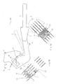
- Fig. 3b is a section b-b of Fig. 3a.
- Fig. 3c is a section c-c of Fig. 3a.
- the clamping region 6 here has a clamping point 17, which is formed by a wall 11 of the Abstreifklemmplatine and a clamping body 18.
- the clamping body 18 is formed for example as a cylinder.
- the clamp body 18 is held on an intermediate wall 19, the two lanes 8 separated from each other. Accordingly, the clamping body 18 projects into two lanes 8 and forms two clamping points 17 in adjacent streets.
- a chamber 14 is provided after the nip 17, can be displaced into the pattern threads 2, when subsequent sections of the pattern threads 2 or other pattern threads 2 claim the space in the nip.
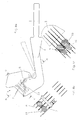
- clamping bodies 18 are again provided whose effect is determined by each a spring 23 is supported.
- Fig. 3a-3c the explanation for Fig. 3a-3c applies.
- the clamping region 6 is formed by a bristle element 20, from which bristles 21 protrude laterally, with which the pattern thread 2 is pressed against the wall 11 of the stripper clamping plate.
- the bristles 21 act with sufficient force on the pattern thread 2 to hold it by clamping.
- the bristle elements 20 may expediently be arranged on a separate socket 22.
- bristles 21 When bristles 21 are used, it is also possible to ensure that the temporary retention of the pattern thread 2 is not caused by a clamping action but by the hooking of the pattern thread 2 in the bristles 21. Of course, a combination between hooking and clamps to hold to use.
- the pattern thread 2 is held in the Abstreifklemmplatine 1 so that it is pulled further and further out of the Abstreifklemmplatine 1 by the required for the knitting process deduction of the web until it has completely detached from the Abstreifklemmplatine 1.
- This makes it possible, for example, to float the pattern threads 2, wherein the pattern threads 2 in the floating section have an increased length, so that they are no longer on the ground the knitwear and later can be easily cut off.
Landscapes
- Engineering & Computer Science (AREA)
- Textile Engineering (AREA)
- Knitting Machines (AREA)
Applications Claiming Priority (1)
| Application Number | Priority Date | Filing Date | Title |
|---|---|---|---|
| DE102006055497A DE102006055497B4 (de) | 2006-11-24 | 2006-11-24 | Musterungshilfsvorrichtung einer Kettenwirkmaschine |
Publications (1)
| Publication Number | Publication Date |
|---|---|
| EP1925700A1 true EP1925700A1 (fr) | 2008-05-28 |
Family
ID=39148286
Family Applications (1)
| Application Number | Title | Priority Date | Filing Date |
|---|---|---|---|
| EP07016979A Withdrawn EP1925700A1 (fr) | 2006-11-24 | 2007-08-30 | Dispositif d'aide à la création de patrons d'un métier à tricoter à mailles jetées |
Country Status (6)
| Country | Link |
|---|---|
| EP (1) | EP1925700A1 (fr) |
| JP (1) | JP4496247B2 (fr) |
| KR (1) | KR20080047271A (fr) |
| CN (1) | CN101187109B (fr) |
| DE (1) | DE102006055497B4 (fr) |
| TW (1) | TWI343428B (fr) |
Families Citing this family (1)
| Publication number | Priority date | Publication date | Assignee | Title |
|---|---|---|---|---|
| ES2548556T3 (es) * | 2013-02-22 | 2015-10-19 | Karl Mayer Textilmaschinenfabrik Gmbh | Barra de plástico para útiles de tricotar |
Citations (3)
| Publication number | Priority date | Publication date | Assignee | Title |
|---|---|---|---|---|
| US3055196A (en) * | 1960-04-27 | 1962-09-25 | Hightstown Rug Company | Apparatus and method for making pile fabric with varying height of pile |
| DE2030197A1 (en) * | 1969-06-25 | 1971-03-04 | Lindner, Heinz, Röscher, Georg, χ 9307 Geyer | Terry fabric produced on crochet galloon - machine |
| DE4301232A1 (de) * | 1993-01-19 | 1994-07-21 | Olbo Textilwerke Gmbh | Verfahren und Einrichtung zur Herstellung textiler netzartiger Flächengebilde |
Family Cites Families (12)
| Publication number | Priority date | Publication date | Assignee | Title |
|---|---|---|---|---|
| DD140767B1 (de) * | 1978-08-21 | 1980-12-10 | Heinz Lindner | Kettenwirkmaschine,insbesondere haekelgalonmaschine zur herstellung jacquardgemusterter polschlingengewirke |
| US4774120A (en) * | 1987-03-09 | 1988-09-27 | Xerkon, Inc. | Method for multiple-end-close-set uniform density parallel weft insertion and products thereof |
| JPH05253377A (ja) * | 1992-03-12 | 1993-10-05 | Barudan Co Ltd | 多針ミシンにおける上糸保持具 |
| JPH0580481U (ja) * | 1992-03-30 | 1993-11-02 | 株式会社大三商会 | 糸端の結び目形成装置 |
| DE4421389C2 (de) * | 1994-06-18 | 1996-09-26 | Mayer Textilmaschf | Jacquardbarre für Kettenwirkmaschinen |
| DE4432222C1 (de) * | 1994-09-10 | 1996-05-02 | Mayer Textilmaschf | Verfahren und Kettenwirkmaschine zur Herstellung einer gemusterten Wirkware |
| DE19514995C2 (de) * | 1995-04-24 | 1997-06-19 | Mayer Textilmaschf | Kettenwirkmaschine |
| JPH0987946A (ja) * | 1995-09-21 | 1997-03-31 | Tsudakoma Corp | 横編機の糸保持装置 |
| AU7904098A (en) * | 1997-07-25 | 1999-02-16 | Textilma Ag | Warp knitting machine, especially crocheting machine |
| JPH1193046A (ja) * | 1997-09-10 | 1999-04-06 | Tsudakoma Corp | 横編機の糸把持装置 |
| DE10048691C1 (de) * | 2000-09-30 | 2002-01-31 | Mayer Textilmaschf | Verfahren und Kettenwirkmaschine zur Herstellung einer gemusterten Wirkware |
| JP4374313B2 (ja) * | 2004-12-28 | 2009-12-02 | 株式会社島精機製作所 | 横編機 |
-
2006
- 2006-11-24 DE DE102006055497A patent/DE102006055497B4/de not_active Expired - Fee Related
-
2007
- 2007-07-27 TW TW096127519A patent/TWI343428B/zh not_active IP Right Cessation
- 2007-08-30 EP EP07016979A patent/EP1925700A1/fr not_active Withdrawn
- 2007-11-15 KR KR1020070116804A patent/KR20080047271A/ko not_active Abandoned
- 2007-11-21 JP JP2007301336A patent/JP4496247B2/ja not_active Expired - Fee Related
- 2007-11-23 CN CN2007101936470A patent/CN101187109B/zh not_active Expired - Fee Related
Patent Citations (3)
| Publication number | Priority date | Publication date | Assignee | Title |
|---|---|---|---|---|
| US3055196A (en) * | 1960-04-27 | 1962-09-25 | Hightstown Rug Company | Apparatus and method for making pile fabric with varying height of pile |
| DE2030197A1 (en) * | 1969-06-25 | 1971-03-04 | Lindner, Heinz, Röscher, Georg, χ 9307 Geyer | Terry fabric produced on crochet galloon - machine |
| DE4301232A1 (de) * | 1993-01-19 | 1994-07-21 | Olbo Textilwerke Gmbh | Verfahren und Einrichtung zur Herstellung textiler netzartiger Flächengebilde |
Also Published As
| Publication number | Publication date |
|---|---|
| DE102006055497A1 (de) | 2008-06-12 |
| CN101187109B (zh) | 2011-03-30 |
| JP4496247B2 (ja) | 2010-07-07 |
| TW200823326A (en) | 2008-06-01 |
| DE102006055497B4 (de) | 2009-01-02 |
| KR20080047271A (ko) | 2008-05-28 |
| TWI343428B (en) | 2011-06-11 |
| JP2008127736A (ja) | 2008-06-05 |
| CN101187109A (zh) | 2008-05-28 |
Similar Documents
| Publication | Publication Date | Title |
|---|---|---|
| DE2910532A1 (de) | Flachstrickmaschine zur herstellung gemusterter strickwaren | |
| DE102009022191B3 (de) | Fadenführeranordnung einer Kettenwirkmaschine | |
| CH694429A5 (de) | Textilmaschine, insbesondere Kettenwirkmaschine. | |
| EP3101164A1 (fr) | Métier à tricoter chaîne et tricot chaîne | |
| DE19651053C1 (de) | Kettenwirkmaschine mit Jacquard-Legebarre | |
| DE2245215C3 (de) | Fadenleiter | |
| EP2141271B1 (fr) | Métier à tricoter rectiligne avec dispositif d'étirage de tricot | |
| EP0591470B1 (fr) | Dispositif pour le serrage et guidage d'aiguilles a crochet pour un metier a crocheter | |
| CH683194A5 (de) | Jacquard-Legebarre für eine Kettenwirkmaschine. | |
| EP1925700A1 (fr) | Dispositif d'aide à la création de patrons d'un métier à tricoter à mailles jetées | |
| DE102010032996B4 (de) | Legebarrenanordnung einer Kettenwirkmaschine | |
| WO1999005351A1 (fr) | Metier a tricoter chaine, en particulier, machine a crochet | |
| AT373299B (de) | Vorrichtung zum mustermaessigen ausrichten mehrerer uebereinander zu legender textilbahnen zur vorbereitung eines zuschnittstapels | |
| CH680785A5 (fr) | ||
| CH658681A5 (de) | Zentral schaltbare fadenbremsvorrichtung. | |
| EP2570536B1 (fr) | Machine à tricoter rectiligne | |
| EP4019682B1 (fr) | Métier à bonneterie ou à tricoter pourvu d'au moins un guide-fil | |
| DE3881078T4 (de) | Nadelauswahlvorrichtung an Strick-, Socken- und Strumpfherstellungsmaschinen und dergleichen. | |
| DE622040C (de) | Fadenfuehrung svorrichtung fuer Kettenwirkmaschinen | |
| DE4407606C1 (de) | Breithalter für eine Strickmaschine | |
| DE488665C (de) | Jacquardeinrichtung | |
| EP0034266A1 (fr) | Dispositif pour supporter des objets | |
| AT225830B (de) | Abstreifvorrichtung für Strickmaschinen | |
| EP1925699A1 (fr) | Procédé de fabrication d'un article tricoté | |
| EP1788131A1 (fr) | Dispositif d'entraînement d'un elément fonctionnel |
Legal Events
| Date | Code | Title | Description |
|---|---|---|---|
| PUAI | Public reference made under article 153(3) epc to a published international application that has entered the european phase |
Free format text: ORIGINAL CODE: 0009012 |
|
| AK | Designated contracting states |
Kind code of ref document: A1 Designated state(s): AT BE BG CH CY CZ DE DK EE ES FI FR GB GR HU IE IS IT LI LT LU LV MC MT NL PL PT RO SE SI SK TR |
|
| AX | Request for extension of the european patent |
Extension state: AL BA HR MK RS |
|
| 17P | Request for examination filed |
Effective date: 20080626 |
|
| 17Q | First examination report despatched |
Effective date: 20080725 |
|
| AKX | Designation fees paid |
Designated state(s): CH DE ES IT LI |
|
| STAA | Information on the status of an ep patent application or granted ep patent |
Free format text: STATUS: THE APPLICATION HAS BEEN WITHDRAWN |
|
| 18W | Application withdrawn |
Effective date: 20131123 |