EP1925753A2 - Excavateur à deux voies. - Google Patents
Excavateur à deux voies. Download PDFInfo
- Publication number
- EP1925753A2 EP1925753A2 EP07018297A EP07018297A EP1925753A2 EP 1925753 A2 EP1925753 A2 EP 1925753A2 EP 07018297 A EP07018297 A EP 07018297A EP 07018297 A EP07018297 A EP 07018297A EP 1925753 A2 EP1925753 A2 EP 1925753A2
- Authority
- EP
- European Patent Office
- Prior art keywords
- way
- traverse
- wheels
- excavator according
- axles
- Prior art date
- Legal status (The legal status is an assumption and is not a legal conclusion. Google has not performed a legal analysis and makes no representation as to the accuracy of the status listed.)
- Withdrawn
Links
Images
Classifications
-
- E—FIXED CONSTRUCTIONS
- E02—HYDRAULIC ENGINEERING; FOUNDATIONS; SOIL SHIFTING
- E02F—DREDGING; SOIL-SHIFTING
- E02F9/00—Component parts of dredgers or soil-shifting machines, not restricted to one of the kinds covered by groups E02F3/00 - E02F7/00
- E02F9/02—Travelling-gear, e.g. associated with slewing gears
- E02F9/022—Travelling-gear, e.g. associated with slewing gears for moving on rails
-
- B—PERFORMING OPERATIONS; TRANSPORTING
- B60—VEHICLES IN GENERAL
- B60F—VEHICLES FOR USE BOTH ON RAIL AND ON ROAD; VEHICLES CAPABLE OF TRAVELLING IN OR ON DIFFERENT MEDIA, e.g. AMPHIBIOUS VEHICLES
- B60F1/00—Vehicles for use both on rail and on road; Conversions therefor
- B60F1/04—Vehicles for use both on rail and on road; Conversions therefor with rail and road wheels on different axles
- B60F1/043—Vehicles comprising own propelling units
-
- B—PERFORMING OPERATIONS; TRANSPORTING
- B60—VEHICLES IN GENERAL
- B60F—VEHICLES FOR USE BOTH ON RAIL AND ON ROAD; VEHICLES CAPABLE OF TRAVELLING IN OR ON DIFFERENT MEDIA, e.g. AMPHIBIOUS VEHICLES
- B60F2301/00—Retractable wheels
- B60F2301/04—Retractable wheels pivotally
Definitions
- the invention relates to a two-way excavator according to the preamble of claim 1.
- two-way excavator which have an undercarriage with at least two axles with wheels for road travel and two pivotable in operating position axles with wheels for rail travel.
- the wheels for rail travel each have two mounted in a mounting frame swing, which are pivotable about hydraulic cylinder about a pivot point.
- Such two-way excavators are multifunctional use.
- they are roadworthy as wheeled vehicles like a conventional wheeled excavator and can drive independently and independently to their place of use.
- the two-way excavator can be converted into a rail vehicle in a very simple manner become.
- the drive is provided by the driven road wheels, which roll on the rail.
- the leadership of the two-way tiller takes place via the rail wheels.
- the object of the invention is therefore to develop a generic two-way excavator such that it can be converted from a two-way excavator with rigid axles in an easy way in a two-way excavator with swing axle.
- the object is achieved by the combination of the features of claim 1. Accordingly, the two mounted in a mounting frame rockers, which carry the pivotable axle with the wheels for rail travel either via a crossbar rigidly connected to each other. Here, therefore, by inserting and connecting to the traverse the respectively the axis overlapping wings are rigidly connected together if necessary.
- a two-way excavator can be designed for transport on the rails with two pendulum axles and, if required, can then be used by a simple handle, the traverse between the wings and connected to the wings.
- the traverse may consist of a closed at each of their ends tube, which is each rigidly connected to the adjacent rocker. Due to the design as a tube, the total weight of the traverse can be kept low with sufficiently high strength. Only the end areas with which the traverse forming tube is closed, must be made of a solid material.
- the rigid connection can be made via a screw connection.
- This screw can be done via laterally introduced from the outside into the rocker screws, which are screwed into a corresponding provided in the end regions of the crossbar thread.
- the traverse can be received in each case with its ends form-fitting manner in the rocker.
- the positive reception can consist in a swing-side slot, in which the end portions of the crosshead, which are shaped according to the shape of the slot, are inserted.
- At least one handle is formed on the crossbar.
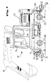
- a two-way excavator 10 is shown, which in the usual way an upper carriage 12 with the driver's cab 16 and a cultivated working tool 18 - here in the form of a spoon attached to a spoon - has.
- the undercarriage 14 has two axles 20 and 22, which are each equipped with twin wheels 16, 18 for road travel.
- the axis 20 is designed as a rigid axle, while the axis 22 is a steered axle.
- attachments 24 and 26 are arranged at both free ends, that is to say at the front and at the rear side of the undercarriage 14, which additionally carry pivotable axes 30 and 32 about pivot points 28.
- the axles 30 and 32 in turn carry wheels 34 and 36 for rail travel.
- the axles 30 and 32 are pivoted respectively via hydraulic cylinders 38 and 40 from a retracted position to a disengaged position in which the axles 20 and 22 are excavated.
- the axes 30 and 32 are shown in partially retracted position, wherein at the front of the two-way hanger 10, the axis 30 is shown in a partially raised position and in a fully pivoted position.
- the pivot radius is located.
- the two-way excavator 10 is ready for driving on the road.
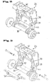
- FIGS. 2 and 3 show details of the attachment 24, which apply in the same way for the attachment 26.
- a mounting frame 42 which can be connected to the undercarriage 14 according to FIG. 1, is shown, which in each case has rockers 44 pivotable laterally about pivot points 28.
- the rockers 44 consist of almost L-shaped sheets, which are pivotable about hydraulic cylinders 38 about the respective pivot points 28.
- the respective axis 30 is mounted.
- a wheel for rail travel 34 is rotatably mounted in each case at its free end.
- the attachments 24 are each shown in a different setup state.
- the axis 30 is designed as a rigid axle, while it is designed in Figure 3 as a pendulum axis. This is due to the fact that in the embodiment according to FIG. 2, the two rockers 44 are firmly connected to one another via a cross member 46. The traverse 46 connects the two wings 44 approximately at the vertex of the L-shaped plates.
- the cross member 46 consists of a tube 48 and two end closure parts 50. These can be made of solid material.
- the outer shape of the closure members 50 may, as shown in the embodiment of Figure 3, be adapted to corresponding provided on the side walls of the rockers 44 slots 52.
- the traverse 48 can be easily inserted into the respective slots 52 in the area of the rockers 44 via their end regions 50.
- To attach the crossbar serve mounting screws 54 which are screwed into associated threaded holes 56 in the end 50 of the cross member 46.
- two handles 58 are formed in the embodiment according to Figures 2 and 3.
- the traverse 46 can be easily connected to the two wings 44, so that a conversion of a pendulum axis 30 of Figure 3 in a rigid axle according to Figure 2 and vice versa in a simple manner is possible.
Landscapes
- Engineering & Computer Science (AREA)
- Mining & Mineral Resources (AREA)
- Civil Engineering (AREA)
- General Engineering & Computer Science (AREA)
- Structural Engineering (AREA)
- Transportation (AREA)
- Mechanical Engineering (AREA)
- Machines For Laying And Maintaining Railways (AREA)
- Handcart (AREA)
- Agricultural Machines (AREA)
Applications Claiming Priority (1)
| Application Number | Priority Date | Filing Date | Title |
|---|---|---|---|
| DE200620017726 DE202006017726U1 (de) | 2006-11-21 | 2006-11-21 | Zweiwegebagger |
Publications (2)
| Publication Number | Publication Date |
|---|---|
| EP1925753A2 true EP1925753A2 (fr) | 2008-05-28 |
| EP1925753A3 EP1925753A3 (fr) | 2009-12-16 |
Family
ID=39000680
Family Applications (1)
| Application Number | Title | Priority Date | Filing Date |
|---|---|---|---|
| EP07018297A Withdrawn EP1925753A3 (fr) | 2006-11-21 | 2007-09-18 | Excavateur à deux voies. |
Country Status (2)
| Country | Link |
|---|---|
| EP (1) | EP1925753A3 (fr) |
| DE (1) | DE202006017726U1 (fr) |
Cited By (1)
| Publication number | Priority date | Publication date | Assignee | Title |
|---|---|---|---|---|
| CN103935285A (zh) * | 2014-04-30 | 2014-07-23 | 四川森田消防装备制造有限公司 | 一种双向行驶路轨两用多功能抢险救援消防车 |
Family Cites Families (10)
| Publication number | Priority date | Publication date | Assignee | Title |
|---|---|---|---|---|
| US3269331A (en) * | 1964-01-30 | 1966-08-30 | Koehring Co | Convertible railway-highway vehicle |
| DE1530127A1 (de) * | 1966-01-20 | 1970-04-23 | Kalamazoo Mfg Company | Kraftfahrzeug zur Fortbewegung auf Eisenbahnschienen und anderen Oberflaechen |
| US3653332A (en) * | 1970-02-12 | 1972-04-04 | Olson & Sons Inc Chas | Convertible rail-highway vehicle |
| US4534297A (en) * | 1982-12-02 | 1985-08-13 | Johnson Sr Theodore C | Wheel position control for railway maintenance vehicle |
| DE8428626U1 (de) * | 1984-09-28 | 1985-03-14 | Fischer, Hans-Jürgen, 8501 Großhabersdorf | Schutzvorrichtung fuer offene kamine |
| DD258434A1 (de) * | 1987-03-09 | 1988-07-20 | Fortschritt Veb K | Adapter fuer mobilbagger und mobilkrane |
| JP2562823Y2 (ja) * | 1992-09-04 | 1998-02-16 | 新キャタピラー三菱株式会社 | 作業車の下部走行体 |
| JP3579911B2 (ja) * | 1993-10-30 | 2004-10-20 | コベルコ建機株式会社 | 軌道用作業機 |
| ES2243178T3 (es) * | 2000-08-10 | 2005-12-01 | Atlas Weyhausen Gmbh | Procedimiento para el apoyo de un equipo de trabajo accionado hidraulicamente y desplazable sobre una via ferrea, asi como equipo de trabajo para la realizacion de este procedimiento. |
| US7201106B2 (en) * | 2002-03-18 | 2007-04-10 | Whiston Joseph L | Hydrostatic hi-rail system |
-
2006
- 2006-11-21 DE DE200620017726 patent/DE202006017726U1/de not_active Expired - Lifetime
-
2007
- 2007-09-18 EP EP07018297A patent/EP1925753A3/fr not_active Withdrawn
Cited By (2)
| Publication number | Priority date | Publication date | Assignee | Title |
|---|---|---|---|---|
| CN103935285A (zh) * | 2014-04-30 | 2014-07-23 | 四川森田消防装备制造有限公司 | 一种双向行驶路轨两用多功能抢险救援消防车 |
| CN103935285B (zh) * | 2014-04-30 | 2015-11-18 | 四川森田消防装备制造有限公司 | 一种双向行驶路轨两用多功能抢险救援消防车 |
Also Published As
| Publication number | Publication date |
|---|---|
| DE202006017726U1 (de) | 2008-04-03 |
| EP1925753A3 (fr) | 2009-12-16 |
Similar Documents
| Publication | Publication Date | Title |
|---|---|---|
| EP2192026B1 (fr) | Machine de traction agricole | |
| EP1925754B1 (fr) | Excavatrice combinée route-rail | |
| DE3912194C2 (de) | Fahrzeug | |
| EP2443285A1 (fr) | Wagon de stockage pour le transport de marchandises en vrac | |
| WO2013064199A1 (fr) | Véhicule rail-route | |
| DE202007018853U1 (de) | Dolly-Achse | |
| WO2020025201A1 (fr) | Attelage comprenant un véhicule tracteur et une remorque, véhicule tracteur, remorque et procédé pour la distribution de charge par essieu dans un attelage | |
| EP2013041B1 (fr) | Appareil de transport | |
| EP3468820B1 (fr) | Engin de chantier, en particulier engin de compactage du sol, plus spécifiquement compacteur à pneu, procédé de fonctionnement d'un engin de chantier et procédé de fabrication d'un engin de chantier | |
| DE9001589U1 (de) | Kranfahrzeug | |
| DE60111711T2 (de) | Zugeinrichtung für einen Anhänger | |
| DE102007044866A1 (de) | Zweiwegebagger | |
| EP1925753A2 (fr) | Excavateur à deux voies. | |
| EP0350008A2 (fr) | Machine pour travailler le sol | |
| DE102012001377B4 (de) | Ballastwagen für einen Derrickkran | |
| DE4137382C1 (en) | Utility site-work vehicle - is articulated with fixed wheels on front carriage and steering wheels on rear carriage. | |
| DE3903400A1 (de) | Motorfahrzeug mit knicklenkung | |
| DE102006044203A1 (de) | Dolly-Achse | |
| DE2322504A1 (de) | Selbstfahrendes knickgelenktes fahrzeug | |
| DE202011106470U1 (de) | Anhänger bzw. Auflieger mit mehreren Achsen | |
| EP1676772A2 (fr) | Machine, en particulier séparateur | |
| DE2600863C2 (de) | Maschine zum Abfräsen oder Abschälen von Straßenbelägen | |
| DE2230469C3 (de) | Fahrbarer Löffelbagger mit antriebslosem Fahrwerk | |
| DE19914385C1 (de) | Golfwagen | |
| EP1782674B1 (fr) | Faucheuse |
Legal Events
| Date | Code | Title | Description |
|---|---|---|---|
| PUAI | Public reference made under article 153(3) epc to a published international application that has entered the european phase |
Free format text: ORIGINAL CODE: 0009012 |
|
| AK | Designated contracting states |
Kind code of ref document: A2 Designated state(s): AT BE BG CH CY CZ DE DK EE ES FI FR GB GR HU IE IS IT LI LT LU LV MC MT NL PL PT RO SE SI SK TR |
|
| AX | Request for extension of the european patent |
Extension state: AL BA HR MK RS |
|
| PUAL | Search report despatched |
Free format text: ORIGINAL CODE: 0009013 |
|
| AK | Designated contracting states |
Kind code of ref document: A3 Designated state(s): AT BE BG CH CY CZ DE DK EE ES FI FR GB GR HU IE IS IT LI LT LU LV MC MT NL PL PT RO SE SI SK TR |
|
| AX | Request for extension of the european patent |
Extension state: AL BA HR MK RS |
|
| AKY | No designation fees paid | ||
| STAA | Information on the status of an ep patent application or granted ep patent |
Free format text: STATUS: THE APPLICATION IS DEEMED TO BE WITHDRAWN |
|
| 18D | Application deemed to be withdrawn |
Effective date: 20100617 |
|
| REG | Reference to a national code |
Ref country code: DE Ref legal event code: 8566 |