EP1925765A2 - Dispositif de verrouillage pour portes - Google Patents
Dispositif de verrouillage pour portes Download PDFInfo
- Publication number
- EP1925765A2 EP1925765A2 EP07020481A EP07020481A EP1925765A2 EP 1925765 A2 EP1925765 A2 EP 1925765A2 EP 07020481 A EP07020481 A EP 07020481A EP 07020481 A EP07020481 A EP 07020481A EP 1925765 A2 EP1925765 A2 EP 1925765A2
- Authority
- EP
- European Patent Office
- Prior art keywords
- snapper
- locking
- locking device
- door
- spring
- Prior art date
- Legal status (The legal status is an assumption and is not a legal conclusion. Google has not performed a legal analysis and makes no representation as to the accuracy of the status listed.)
- Withdrawn
Links
Images


Classifications
-
- E—FIXED CONSTRUCTIONS
- E05—LOCKS; KEYS; WINDOW OR DOOR FITTINGS; SAFES
- E05B—LOCKS; ACCESSORIES THEREFOR; HANDCUFFS
- E05B53/00—Operation or control of locks by mechanical transmissions, e.g. from a distance
- E05B53/003—Operation or control of locks by mechanical transmissions, e.g. from a distance flexible
-
- E—FIXED CONSTRUCTIONS
- E05—LOCKS; KEYS; WINDOW OR DOOR FITTINGS; SAFES
- E05B—LOCKS; ACCESSORIES THEREFOR; HANDCUFFS
- E05B15/00—Other details of locks; Parts for engagement by bolts of fastening devices
- E05B15/10—Bolts of locks or night latches
- E05B15/102—Bolts having movable elements
-
- E—FIXED CONSTRUCTIONS
- E05—LOCKS; KEYS; WINDOW OR DOOR FITTINGS; SAFES
- E05B—LOCKS; ACCESSORIES THEREFOR; HANDCUFFS
- E05B55/00—Locks in which a sliding latch is used also as a locking bolt
- E05B55/12—Locks in which a sliding latch is used also as a locking bolt the bolt being secured by the operation of a hidden parallel member ; Automatic latch bolt deadlocking mechanisms, e.g. using a trigger or a feeler
-
- E—FIXED CONSTRUCTIONS
- E05—LOCKS; KEYS; WINDOW OR DOOR FITTINGS; SAFES
- E05C—BOLTS OR FASTENING DEVICES FOR WINGS, SPECIALLY FOR DOORS OR WINDOWS
- E05C1/00—Fastening devices with bolts moving rectilinearly
- E05C1/08—Fastening devices with bolts moving rectilinearly with latching action
-
- E—FIXED CONSTRUCTIONS
- E05—LOCKS; KEYS; WINDOW OR DOOR FITTINGS; SAFES
- E05C—BOLTS OR FASTENING DEVICES FOR WINGS, SPECIALLY FOR DOORS OR WINDOWS
- E05C9/00—Arrangements of simultaneously actuated bolts or other securing devices at well-separated positions on the same wing
-
- E—FIXED CONSTRUCTIONS
- E05—LOCKS; KEYS; WINDOW OR DOOR FITTINGS; SAFES
- E05C—BOLTS OR FASTENING DEVICES FOR WINGS, SPECIALLY FOR DOORS OR WINDOWS
- E05C9/00—Arrangements of simultaneously actuated bolts or other securing devices at well-separated positions on the same wing
- E05C9/002—Arrangements of simultaneously actuated bolts or other securing devices at well-separated positions on the same wing with arrangements allowing the wing to be slam-shut, e.g. by securing elements with latching action
-
- E—FIXED CONSTRUCTIONS
- E05—LOCKS; KEYS; WINDOW OR DOOR FITTINGS; SAFES
- E05C—BOLTS OR FASTENING DEVICES FOR WINGS, SPECIALLY FOR DOORS OR WINDOWS
- E05C9/00—Arrangements of simultaneously actuated bolts or other securing devices at well-separated positions on the same wing
- E05C9/18—Details of fastening means or of fixed retaining means for the ends of bars
- E05C9/1825—Fastening means
- E05C9/1833—Fastening means performing sliding movements
- E05C9/185—Fastening means performing sliding movements parallel with actuating bar
Definitions
- the invention relates to a locking device for doors, in particular for cabinet doors with a plurality of locking elements and with an actuator disposed on the door, which is connected directly or indirectly with the respective locking elements.
- Locking devices having a plurality of locking elements are already used in cabinet doors, wherein on the one hand via a handle or a key-actuable catch a bolt and additionally one or two push rods are movable.
- the simultaneous operation is possible by a pivot connection on the lock as an actuator.
- the lock operation can be done via a mechanical or electric motor drive.
- the well-known mechanical lock operation requires a high expenditure of force or a multiple turning of a key to the bolt operation and at the same time to move the push rods in a locked position or for unlocking. There is a risk of billing or twisting the key. To prevent this, a comprehensive mechanism over one or more gear is provided to reduce the increased force. Another disadvantage of these devices is the high risk of burglary.
- the key is removable only in the closed position. Especially with tool cabinets that should be accessible over the entire working time, therefore, the locking device is brought into a locked position with the door open, so that the key can be removed.
- An inserted key poses a risk of injury on the one hand and should be stored safely on the other hand. Open doors are disturbing and are therefore often slammed carelessly. In this case, it can lead to bending of the push rods, which can lead to the fact that the door is no longer lockable. In this case, the entire pushrod must be replaced. It would therefore be desirable to prevent damage to the locking element upon slamming the door.
- the object of the invention is therefore to provide a locking device for doors with one or more locking elements available, fail in the burglary attempts by manipulation of a locking element and in which the risk of damage to the locking elements is lower than in known locking devices.
- This object is achieved with a locking device according to claim 1.
- This locking device has one or more locking elements, which are arranged on a door at the Actuator can be moved together from the locked position to an unlocked position. By unlocking all locking elements, it is possible to open or close the door.
- the actuating device may be a known lock with a mechanical or electromotive drive.
- a locking element is a known latch, which is usually connected directly to the actuator and can be brought by this from a locked position to an unlocked position and blocked in the locked position by a closing operation.
- At least one further locking element is provided. This can be arranged for example in the area of the top or bottom of the door. However, this locking element is not connected by a rigid linkage, such as a push rod, with the actuator, but indirectly or directly via a flexible connection, such as a cable. This additional locking element is brought from its locked position by use of the actuator.
- This new locking element has an inner and an outer snapper, which are movably mounted in a housing which is fixed to the door.
- the snapper are loaded directly or indirectly in each case via a spring in the closing direction. Both snapper are in operative connection with each other and are preferably mutually displaceable.
- the locking of the door is effected by the inner latch, which engages in a designated opening on the frame, wherein the outer latch outside the opening, preferably adjacent to this opening abuts the frame.
- both snapper When unlocking by the actuator both snapper are pulled against the spring force until they retracted so far into the housing are that the door can be opened. With the door open, both snapper are brought by the spring forces acting on them in a relaxed state without the action of the actuator, ie the snapper move according to the maximum allowable displacement length out of the housing.
- the snapper have a corresponding cross-sectional shape, namely an inlet slope, which facilitates the closing of the door.
- the inner latch is located immediately opposite the intended opening in the frame, i.
- the inner snapper can extend again in the closing direction.
- the outer snapper will take this sliding movement until it strikes with its end face on the frame adjacent to the opening. It is only the inner snapper moved in the closing direction, but this is possible by the mutual displacement of both snapper.
- the inner snapper is located in a channel-shaped opening within the outer snapper. This channel is aligned in the closing direction, so that a longitudinal displacement in the opening direction and in the closing direction is possible.
- the limitation of the stroke of the inner snapper, i. the determination of the maximum displacement length is secured by a recess provided on the housing of the locking element, in which engages the inner snapper with a molded onto the inner snapper nipple.
- the sliding movement of both snapper is due to the existing between two snappers active joint together, wherein in the sliding movement of the outer snapper the same displacement length or when blocking a smaller displacement length as the inner snapper travels, such as when closing the door, where the further displacement of the outer snap is prevented by hitting the frame. Even with this different displacement of the snapper the operative connection between the two snappers is not canceled.
- the inner snapper is located in a channel passing through the outer snapper.
- the outer snapper has a U-shape, so that in the relaxed state of the locking element of the inner snapper is flanked on the left and right of thighs of the outer snapper.
- the operative connection between the snappers can be achieved in a preferred embodiment via a toothing and a spring element, wherein the toothing is aligned in the closing direction and is located on the wall of the channel of the outer snapper.
- two opposing teeth are provided on the wall of the channel. In each of these opposing teeth engages one end of the transverse arm of the T-shaped spring element.
- the transverse arm of the T-shaped spring element is preferably convexly curved in the direction of the inner snap and is supported on the underside of the inner snapper.
- Such a spring element can be formed from a steel strip, wherein the beginning and the end of the steel strip form the foot of the beam of the T-shaped spring element.
- This foot of the beam is aligned in the direction of the actuator and has a connection point for the connection with the actuator, for example for connecting a pull rope or a cable.
- a strain relief is provided so that not the entire force of the actuating element acts on the spring element.
- the locking position of the new locking element requires no counterforce from the linkage. It is realized solely by the spring force of the springs supporting the snapper. This also facilitates unlocking of these locking elements by the actuating device.
- the resilient mounting of the snapper prevents damage to the snap when careless slamming the door, as they can escape the pressure of the frame.
- the 1 shows a door 11 arranged in a frame 12, equipped with the locking device 10 according to the invention.
- the door 11 in this case is a cabinet door.
- the locking device 10 can be used in the same way for doors in which a lock on the frame of the door takes place.
- the locking device 10 has in this case three locking elements 17, 20.
- the middle locking element 17 engages with a latch 18 in an opening on the frame 12 a.
- This locking member 17 is moved by the actuator 15 from the locking position where the latch 18 engages the opening 14 on the frame 12 in an unlocked position where the latch is moved out of this opening by pivoting or retracting.
- a lock 16 which performs an unlocking with the appropriate key and causes the movement of the bolt from the locked position to the unlocked position by means of the handle.
- a lever or a knob can be used.
- an electromotive actuation is possible.
- the actuator 15 is connected via cables 19 with an upper and lower locking element 20.
- the locking elements 20 are attached to the door 11 and have a snapper 22 which engages in the blocking position in an opening provided 13 on the frame 12.
- the number of these additional locking elements 20 can ever Use case are determined. It can be both a locking element 20 and more than two locking elements 20.
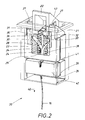
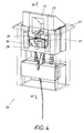
- the locking element 20 is shown in its function in FIGS. 2 and 4.
- Fig. 2 the locking position of the locking element 20 is shown.
- the inner snapper 22 is located in the intended opening 13 of the frame 12, as shown in Fig. 1.
- the door 11 and the frame 12 have been omitted in Figs. 2 to 4 for the sake of clarity.
- a housing 21 of the locking element 20 is fixed.
- the snapper 22 and 23 are spring-mounted.
- a determination of the interconnected snapper 22, 23 in the housing 21 via integrally formed on the outer snapper 23 locking arms which hook in the housing 21.
- Both snappers 22, 23 are each loaded via at least one spring 24, 25 in the closing direction 33.
- the inner snapper 22 is connected to the underside 35 with two springs 24, which are supported on a support surface 26 of the housing 21.
- the inner snapper 22 is in the extended position, i. in a relaxed state.
- the snapper 22 is longitudinally displaceable within a channel 34 which passes through the outer snapper 23.
- a nipple 31 formed on the inner gate 22 engages a longitudinally aligned recess 30.
- the inner gate 22 is in the extended position, i. the nipple 31 abuts the upper end of the recess 30.
- the inner snapper 22 has thus reached its maximum displacement length in the locked position.
- the outer snapper 23 has a U-shaped cross-section, ie it engages around with its two legs, the inner snapper 22.
- This snapper 23 is designed to be longitudinally displaceable and resiliently mounted.
- a spring 25 is provided, between the support surface 26 of the housing 21 and the underside the outer snapper 23 is arranged. The spring force of this spring 25 causes a movement of the outer snapper 23 in the closing direction 33, in this case upwards.
- the locking element 20 is in the locked position, ie the door 11 is closed and the frame 12 prevents the outer snapper 23 is further extended.
- the left and right end stop surface 27 of the outer snapper 23 abuts the frame 12, whereby the sliding movement of the outer snapper 23 is blocked despite acting spring force of the spring 25. Since the outer snapper 23 always extends as far as the door closed until it comes to the stop on the frame 12, even with different gap dimensions between the door 11 and frame 12 prevents introduced into the gap between the door 11 and 12 tool on the inner snapper 22, which causes the lock can attack.
- inner snapper 22 and outer snapper 23 in the direction of the spring force of the springs 24, 25 can move automatically or can be by a counter-pressure against the spring force of the spring 24, 25 in the opposite direction, ie in the housing 21, move ,
- the snapper 22 and 23 are connected to each other, so that the sliding movement can be performed simultaneously on the other hand, on the other hand, in a blockage, the snapper 22, 23 also move against each other, ie only a snap, for example, the inner snapper 22, move alone.
- the operative connection between the inner snapper 22 and the outer snapper 23 is ensured by a toothing 28 provided on the inner snapper 23 and a spring element 29. This spring element 29 is formed in this case almost T-shaped.
- the transverse arm 37 of this spring element 29 abuts on the bottom 35 of the inner snapper 22 from below.
- this transverse arm 37 is preferably curved convexly, the bulge striking the underside 25.
- the ends 36 of the cross arm 37 engage left and right in the Gearing 28 a.
- the transverse arm 37 then goes down into the vertical bar 38 of the spring element 29 via.
- the left and right teeth 28 are arranged on the outer snapper 23, and indeed within the channel 34, in which the inner snapper 22 is provided and can be moved by acting on the spring element 29.
- the spring element 29 supports the inner snapper 22 on the outer snapper 23, in addition to the resilient mounting of the spring 24 from.
- the outer snapper 23 first reaches its lower position, ie disappears within the housing 21, but only as far as it allows a projecting into the displacement of the inner snapper 22 provided in the interior of the housing 21 boundary surface 41. Now, if the tensile force is further maintained by the actuator 15, the spring element 29 moves within the toothing 28, ie tooth by tooth, down. This allows retraction of the inner snapper 22 into the housing 21. This displacement of the inner snap 22 in the opening direction 40 is also limited, namely by the abutment of the nipple 31 at the lower boundary of the recess 30. This state is shown in Fig. 3. Both snapper 22, 23 are located after unlocking within the housing 21st
- the two snapper 22, 23 extend due to the force acting on them spring forces of the springs 24, 25 back out of the housing 21 with the maximum possible displacement length.
- the snapper 22, 23 are in this case in a relaxed state which is shown in Fig. 4.
- the snapper 22, 23 in the area that can extend out of the housing 21 has an inlet slope 43 against which the frame 12 presses when closing the door.
Landscapes
- Engineering & Computer Science (AREA)
- Mechanical Engineering (AREA)
- Lock And Its Accessories (AREA)
Applications Claiming Priority (1)
| Application Number | Priority Date | Filing Date | Title |
|---|---|---|---|
| DE200610054745 DE102006054745B4 (de) | 2006-11-21 | 2006-11-21 | Verriegelungsvorrichtung für Türen |
Publications (2)
| Publication Number | Publication Date |
|---|---|
| EP1925765A2 true EP1925765A2 (fr) | 2008-05-28 |
| EP1925765A3 EP1925765A3 (fr) | 2011-06-15 |
Family
ID=39092094
Family Applications (1)
| Application Number | Title | Priority Date | Filing Date |
|---|---|---|---|
| EP07020481A Withdrawn EP1925765A3 (fr) | 2006-11-21 | 2007-10-19 | Dispositif de verrouillage pour portes |
Country Status (2)
| Country | Link |
|---|---|
| EP (1) | EP1925765A3 (fr) |
| DE (1) | DE102006054745B4 (fr) |
Cited By (3)
| Publication number | Priority date | Publication date | Assignee | Title |
|---|---|---|---|---|
| US20130320692A1 (en) * | 2012-05-31 | 2013-12-05 | Dr. Ing. H.C.F. Porsche Aktiengesellschaft | Locking device |
| EP3626918A1 (fr) * | 2018-09-19 | 2020-03-25 | TSH System GmbH - Gesellschaft für Systemlösungen des Tischler- und Schreinerhandwerks mbH | Ferrure pour une fenêtre, fenêtre |
| CN112751272A (zh) * | 2020-12-17 | 2021-05-04 | 广德因达电炉成套设备有限公司 | 一种全自动超大电流切换开关 |
Families Citing this family (2)
| Publication number | Priority date | Publication date | Assignee | Title |
|---|---|---|---|---|
| EP4196656A4 (fr) * | 2020-08-17 | 2024-11-13 | Mac Donald, David Johannes | Verrou de porte de conteneur intermodal |
| DE102024135522A1 (de) | 2024-11-29 | 2026-06-03 | Cambaum Gmbh | Durchgangsschleuse |
Citations (1)
| Publication number | Priority date | Publication date | Assignee | Title |
|---|---|---|---|---|
| EP0348971A2 (fr) | 1988-07-01 | 1990-01-03 | BKS GmbH | Verrou relâché lors de la fermeture d'une porte, notamment pour crémone de porte, fenêtre, etc. |
Family Cites Families (7)
| Publication number | Priority date | Publication date | Assignee | Title |
|---|---|---|---|---|
| US1876081A (en) * | 1929-03-05 | 1932-09-06 | Schlage Lock Co | Door latch |
| DE2638313C3 (de) * | 1976-08-25 | 1979-07-19 | Hoermann Kg Amshausen, 4803 Steinhagen | Verriegelungsvorrichtung für ein Schwingtor |
| US5028083A (en) * | 1990-04-27 | 1991-07-02 | Motorola, Inc. | Latch assembly |
| DE9218163U1 (de) * | 1992-08-25 | 1993-09-16 | Ernst Friedrich Heuer GmbH, 73278 Schlierbach | Schließvorrichtung für Rolltore |
| DE9421217U1 (de) * | 1994-02-22 | 1995-08-03 | Englert, Dieter, 63869 Heigenbrücken | Schließeinrichtung mit mindestens einem zusätzlichen Sicherungsriegel |
| US5398447A (en) * | 1994-02-28 | 1995-03-21 | Morse; Allen D. | Centrally located tilt-in window handle |
| US6708625B1 (en) * | 1999-07-02 | 2004-03-23 | Zeftek, Inc. | Greaseless door lock |
-
2006
- 2006-11-21 DE DE200610054745 patent/DE102006054745B4/de not_active Expired - Fee Related
-
2007
- 2007-10-19 EP EP07020481A patent/EP1925765A3/fr not_active Withdrawn
Patent Citations (1)
| Publication number | Priority date | Publication date | Assignee | Title |
|---|---|---|---|---|
| EP0348971A2 (fr) | 1988-07-01 | 1990-01-03 | BKS GmbH | Verrou relâché lors de la fermeture d'une porte, notamment pour crémone de porte, fenêtre, etc. |
Cited By (5)
| Publication number | Priority date | Publication date | Assignee | Title |
|---|---|---|---|---|
| US20130320692A1 (en) * | 2012-05-31 | 2013-12-05 | Dr. Ing. H.C.F. Porsche Aktiengesellschaft | Locking device |
| US9169674B2 (en) * | 2012-05-31 | 2015-10-27 | Dr. Ing. H.C. F. Porsche Aktiengesellschaft | Locking device |
| EP3626918A1 (fr) * | 2018-09-19 | 2020-03-25 | TSH System GmbH - Gesellschaft für Systemlösungen des Tischler- und Schreinerhandwerks mbH | Ferrure pour une fenêtre, fenêtre |
| CN112751272A (zh) * | 2020-12-17 | 2021-05-04 | 广德因达电炉成套设备有限公司 | 一种全自动超大电流切换开关 |
| CN112751272B (zh) * | 2020-12-17 | 2024-01-30 | 广德因达电炉成套设备有限公司 | 一种全自动超大电流切换开关 |
Also Published As
| Publication number | Publication date |
|---|---|
| EP1925765A3 (fr) | 2011-06-15 |
| DE102006054745B4 (de) | 2014-08-14 |
| DE102006054745A1 (de) | 2008-05-29 |
Similar Documents
| Publication | Publication Date | Title |
|---|---|---|
| EP3165703A2 (fr) | Dispositif d'étanchéité abaissable | |
| DE4303400C2 (de) | Treibstangenschloss mit Abdicht- und Sicherheitsfunktion ß | |
| DE202007015503U1 (de) | Treibstangengetriebe | |
| EP1243729B1 (fr) | Dispositif de verrouillage à tige d'actionnement pour une fenêtre, une porte ou similaire | |
| DE9104553U1 (de) | Mehrriegel-Türschloß | |
| DE10219692A1 (de) | Verriegelungsbeschlag an einem Fenster, eienr Tür oder dergleichen, mit gegenläufig verschiebbaren Treibstangen | |
| DE102006054745B4 (de) | Verriegelungsvorrichtung für Türen | |
| DE69609988T2 (de) | Türsicherheitsvorrichtung | |
| EP2796647A1 (fr) | Crémone-serrure | |
| DE102015000606A1 (de) | Verriegelungsvorrichtung für einen schwenkbar gelagerten Flügel | |
| EP2140087B1 (fr) | Armature | |
| AT406883B (de) | Sperre gegen das zurückdrücken eines ausgeschobenen riegels | |
| DE19628011C2 (de) | Spereinrichtung für die Riegel eine Riegelwerks | |
| EP2159358B1 (fr) | Verrou pour un composant destiné à la fermeture d'une ouverture | |
| EP0974721B1 (fr) | Serrure à plusieurs pênes | |
| AT406597B (de) | Mehrriegelschloss mit wechselbetätigung | |
| DE3935990C2 (fr) | ||
| EP2754801B2 (fr) | Gâche ou serrure à mortaiser | |
| DE102012200640A1 (de) | Antriebsvorrichtung für eine gemeinsame Betätigung eines Zentralverschlusses und des Flügels eines Fensters oder einer Türe | |
| EP2453086B1 (fr) | Ferrure de crémone pour battant fixe de fenêtres ou de portes à deux vantaux sans montant médian | |
| EP2085543B1 (fr) | Serrure | |
| EP4249715B1 (fr) | Dispositif de verrouillage d'un battant de porte | |
| EP1373670B1 (fr) | Systeme de fermeture pour une armoire a volets roulants | |
| EP3215696A1 (fr) | Serrure | |
| DE102009009259B4 (de) | Zuhaltung für ein Bauteil zum Verschließen einer Öffnung |
Legal Events
| Date | Code | Title | Description |
|---|---|---|---|
| PUAI | Public reference made under article 153(3) epc to a published international application that has entered the european phase |
Free format text: ORIGINAL CODE: 0009012 |
|
| AK | Designated contracting states |
Kind code of ref document: A2 Designated state(s): AT BE BG CH CY CZ DE DK EE ES FI FR GB GR HU IE IS IT LI LT LU LV MC MT NL PL PT RO SE SI SK TR |
|
| AX | Request for extension of the european patent |
Extension state: AL BA HR MK RS |
|
| PUAL | Search report despatched |
Free format text: ORIGINAL CODE: 0009013 |
|
| AK | Designated contracting states |
Kind code of ref document: A3 Designated state(s): AT BE BG CH CY CZ DE DK EE ES FI FR GB GR HU IE IS IT LI LT LU LV MC MT NL PL PT RO SE SI SK TR |
|
| AX | Request for extension of the european patent |
Extension state: AL BA HR MK RS |
|
| RIC1 | Information provided on ipc code assigned before grant |
Ipc: E05C 9/00 20060101ALI20110511BHEP Ipc: E05B 55/12 20060101ALI20110511BHEP Ipc: E05C 9/04 20060101ALI20110511BHEP Ipc: E05C 1/08 20060101ALI20110511BHEP Ipc: E05B 53/00 20060101ALI20110511BHEP Ipc: E05B 15/10 20060101AFI20080226BHEP |
|
| 17P | Request for examination filed |
Effective date: 20111123 |
|
| AKX | Designation fees paid |
Designated state(s): AT BE BG CH CY CZ DE DK EE ES FI FR GB GR HU IE IS IT LI LT LU LV MC MT NL PL PT RO SE SI SK TR |
|
| GRAP | Despatch of communication of intention to grant a patent |
Free format text: ORIGINAL CODE: EPIDOSNIGR1 |
|
| STAA | Information on the status of an ep patent application or granted ep patent |
Free format text: STATUS: THE APPLICATION HAS BEEN WITHDRAWN |
|
| 18W | Application withdrawn |
Effective date: 20130308 |