EP1925811A1 - Pompe pour fluide, en particulier pompe manuelle pour un moteur diesel - Google Patents
Pompe pour fluide, en particulier pompe manuelle pour un moteur diesel Download PDFInfo
- Publication number
- EP1925811A1 EP1925811A1 EP06024302A EP06024302A EP1925811A1 EP 1925811 A1 EP1925811 A1 EP 1925811A1 EP 06024302 A EP06024302 A EP 06024302A EP 06024302 A EP06024302 A EP 06024302A EP 1925811 A1 EP1925811 A1 EP 1925811A1
- Authority
- EP
- European Patent Office
- Prior art keywords
- sleeve
- pump
- inlet
- outlet
- pumping
- Prior art date
- Legal status (The legal status is an assumption and is not a legal conclusion. Google has not performed a legal analysis and makes no representation as to the accuracy of the status listed.)
- Granted
Links
Images


Classifications
-
- F—MECHANICAL ENGINEERING; LIGHTING; HEATING; WEAPONS; BLASTING
- F02—COMBUSTION ENGINES; HOT-GAS OR COMBUSTION-PRODUCT ENGINE PLANTS
- F02M—SUPPLYING COMBUSTION ENGINES IN GENERAL WITH COMBUSTIBLE MIXTURES OR CONSTITUENTS THEREOF
- F02M37/00—Apparatus or systems for feeding liquid fuel from storage containers to carburettors or fuel-injection apparatus; Arrangements for purifying liquid fuel specially adapted for, or arranged on, internal-combustion engines
- F02M37/04—Feeding by means of driven pumps
- F02M37/16—Feeding by means of driven pumps characterised by provision of personally-, e.g. manually-, operated pumps
-
- F—MECHANICAL ENGINEERING; LIGHTING; HEATING; WEAPONS; BLASTING
- F02—COMBUSTION ENGINES; HOT-GAS OR COMBUSTION-PRODUCT ENGINE PLANTS
- F02M—SUPPLYING COMBUSTION ENGINES IN GENERAL WITH COMBUSTIBLE MIXTURES OR CONSTITUENTS THEREOF
- F02M37/00—Apparatus or systems for feeding liquid fuel from storage containers to carburettors or fuel-injection apparatus; Arrangements for purifying liquid fuel specially adapted for, or arranged on, internal-combustion engines
- F02M37/04—Feeding by means of driven pumps
-
- F—MECHANICAL ENGINEERING; LIGHTING; HEATING; WEAPONS; BLASTING
- F02—COMBUSTION ENGINES; HOT-GAS OR COMBUSTION-PRODUCT ENGINE PLANTS
- F02M—SUPPLYING COMBUSTION ENGINES IN GENERAL WITH COMBUSTIBLE MIXTURES OR CONSTITUENTS THEREOF
- F02M37/00—Apparatus or systems for feeding liquid fuel from storage containers to carburettors or fuel-injection apparatus; Arrangements for purifying liquid fuel specially adapted for, or arranged on, internal-combustion engines
- F02M37/04—Feeding by means of driven pumps
- F02M37/14—Feeding by means of driven pumps the pumps being combined with other apparatus
-
- F—MECHANICAL ENGINEERING; LIGHTING; HEATING; WEAPONS; BLASTING
- F04—POSITIVE - DISPLACEMENT MACHINES FOR LIQUIDS; PUMPS FOR LIQUIDS OR ELASTIC FLUIDS
- F04B—POSITIVE-DISPLACEMENT MACHINES FOR LIQUIDS; PUMPS
- F04B9/00—Piston machines or pumps characterised by the driving or driven means to or from their working members
- F04B9/14—Pumps characterised by muscle-power operation
Definitions
- the invention relates to a pump for a fluid medium, in particular for manual use in diesel-fueled internal combustion engines.
- Pumps for the delivery of fuels are known in practice in various embodiments. These pumps are usually installed between a tank and a fuel pump of the injection system of an internal combustion engine. During operation of the internal combustion engine, the motor-driven fuel delivery pump supplies the injection system with fuel. For example, if the tank-side fuel system is vented after a complete fuel extraction, the fuel delivery pump after filling the tank can not vent the completely empty fuel line. To avoid damage to the fuel pump, the fuel line is usually vented with a manually operated pump.
- the pumps known from practice consist of a pump chamber provided with inlet and outlet. The tank-side fuel line is connected to the inlet, the engine-side fuel line to the outlet.
- both the inlet and the outlet are provided with valves.
- different pumps which are known, which are equipped with different valve types.
- the valves must also be flowed through in normal operation of the internal combustion engine, resulting in large pressure losses during the fuel delivery process. This also means that the performance of the fuel delivery pump must be designed to be significantly oversized, making their production consuming and expensive.
- the requirements that are currently being placed by high-pressure injection diesel engines, the known from the prior art pumps can not satisfy satisfactorily because of the high pressure drop.
- the invention is based on the technical problem of specifying a pump, which is flowed through by a fuel flow with the lowest possible pressure loss during normal operation of an internal combustion engine and with which the fuel line can nonetheless be vented easily and funtionsêt.
- the invention teaches a pump for a fluid medium, in particular for manual use in diesel-fueled internal combustion engines, wherein a housing is provided with at least one inlet and at least one outlet for the fluid medium, wherein a pump means for the fluid medium is connected to the housing, wherein at least one pumping state, in which the fluid medium can be conveyed by means of the pumping device, and at least one operating state, in which the fluid medium flows from the inlet to the outlet, is adjustable and wherein in the operating state, a connection between the inlet and the outlet can be produced without blocking element.
- the housing of the pump is made of at least one metal.
- the housing preferably consists of at least one plastic.
- the housing is made at least partially transparent, so that it can already be determined by visual inspection whether the fuel supply line supplying the fuel line is free of air.
- the housing consists of at least one metal and at least one plastic.
- at least parts of the pump are transparent.
- the housing is equipped with fastening elements, which are preferably designed as bores.
- the housing of the pump according to the invention preferably has an inlet and an outlet, which are very preferably cylindrical and expediently have the same diameter.
- the longitudinal axes of the cylindrically shaped inlet and the cylindrically shaped outlet are aligned.
- at least the inlet and / or the outlet is provided with an internal thread.
- the housing is provided with a chamber which is connected to the inlet and with the outlet, wherein in the chamber a sleeve is movably mounted and wherein by means of the sleeve the shut-off element-free connection between the inlet and the outlet can be produced.
- the geometric shape of the chamber is basically arbitrary, but preferred is a cylindrical configuration.
- the chamber extends over at least part of the case. Both inlet and outlet are typically connected to the chamber.
- One end of the chamber is expediently provided with a first opening which extends over the entire cylinder cross-section.
- a second opening extending at least over part of the cross section of the chamber is provided. The second opening is very preferably surrounded on the outside of the housing radially by a recess.
- the chamber is preferably arranged in the housing so that its central axis is perpendicular to the longitudinal axis of the aligned inlet and outlet, more preferably intersect the central axis of the chamber and the longitudinal axis of the aligned inlet and outlet.
- a sleeve is embedded in the chamber, which has a pump section and a passage section. It is within the scope of the invention that the sleeve is provided with a centering element which engages in the second opening of the chamber. The centering element is preferably centered on the passage section side base of the sleeve, externally arranged cylindrical projection. The sleeve preferably closes off in a form-fitting manner with the chamber.
- the sleeve is provided with at least one, the outer circumference completely circumferential receiving groove into which a sealing element is received.
- both the pump section and the passage section are provided with at least one peripheral receiving groove for receiving sealing elements.
- sealing elements which are designed as O-rings.
- a receiving groove is also present in the centering element. It is within the scope of the invention that the sleeve is held in the chamber by a clamping ring located in the receiving groove of the centering element. In this case, the clamping ring is preferably supported in the recess surrounding the second opening on the outside of the housing.
- the sleeve is rotatably mounted in the chamber.
- a 90 ° rotation of the sleeve in the chamber is expediently carried out.
- a groove covering the radian measure in question is very preferably provided in the chamber, into which groove a pin attached to the sleeve engages.
- the groove is arranged at a radial distance from the second opening. The pin is then preferably arranged on the outside of the passage section side base of the sleeve.
- the sleeve is preferably provided with at least one through-channel, preferably with two through-channels, namely with a first and a second through-channel.
- the sleeve has in its passage section at least a first passage, wherein the first passage in a preferred embodiment is cylindrical.
- the first passage is suitably arranged so that its longitudinal axis is oriented perpendicular to the longitudinal axis of the sleeve.
- the longitudinal axis of the first passageway intersects the longitudinal axis of the sleeve. It is within the scope of the invention that the diameter of the through-channel is at least as large as the diameter of the inlet and outlet.
- a second passageway is arranged, which is expediently arranged perpendicular to the first passageway and to the longitudinal axis of the sleeve.
- the first and the second passage are in a plane and form a common cutting chamber in their cutting area.
- the cutting chamber with the interior of the pump portion of the sleeve by means of a Connection channels connected.
- the diameter of the first passageway deviates from a preferred embodiment of the second passageway from.
- a preferred embodiment is characterized in that it is switchable by moving the sleeve from the operating state to the pumping state and vice versa and the sleeve is expediently engaged both in the operating state and in the pumping state.
- the chamber of the housing is equipped with a locking device which locks the sleeve in certain positions.
- a recess with a tapered edge is preferably arranged in the chamber.
- a spring element and a ball are suitably added, wherein the diameter of the ball is greater than the diameter of the recess.
- This locking device is most preferably positioned at the end of the chamber to which the second opening is arranged.
- the sleeve then preferably has indentations on the outer side on the passage section-side base surface into which the ball segment projecting from the recess preferably engages positively in locking positions.
- flow channels for the fluid medium are advantageously formed.
- a first flow channel consisting of the inlet, the first passage and the outlet formed.
- a second flow channel consisting of the inlet, the second passage and the outlet, is formed.
- the first flow channel is assigned to the operating state and the second flow channel is assigned to the pumping state.
- the first flow channel is expediently formed. It is within the scope of the invention that the first flow channel is absperrelementok. In the first flow channel so no shut-off elements such as shut-off valves, throttle valves or valves are arranged.
- the second through-channel of the sleeve connects the inlet to the outlet, wherein in the second flow channel for the fluid medium associated with the pumping state at least one shut-off element, preferably two shut-off elements are arranged.
- the second passage preferably has at least one shut-off element.
- Two shut-off elements are particularly preferably placed in the second passage, between which, in a very preferred embodiment, the connection channel is arranged between the intersection volume and the interior of the pump section of the sleeve.
- the shut-off elements are very particularly preferably installed so that both shut-off elements are permeable only in the flow direction pointing from the inlet to the outlet.
- the sleeve has a pump portion forming the pumping section, wherein in the pump portion, a movable piston is accommodated, which is equipped with a support plate, and wherein the sleeve has a passage portion in which the at least one passage channel is arranged.
- the pumping section of the sleeve is preferably integrally connected to the passage section.
- a piston is preferably movably mounted.
- the piston preferably consists of an actuating element, a piston rod, a support plate and a sealing element, wherein the sealing element terminates fluid-tight with the inner wall of the pump section.
- the sealing element is preferably pushed onto a thickening of the piston rod and is supported by the support plate. Particularly preferably, the sealing element is pushed onto the support plate.
- a cover is expediently placed, which can be screwed, welded or pressed with this.
- the lid has a centered opening through which the piston rod is guided.
- the protruding from the lid piston rod is provided with an actuating element, which is preferably fixed to the lid at least in the operating state of the pump.
- the fixation can be made by a screw or the actuator can also be fixed to the lid with a locking device.
- the pump section can also be replaced by a motor-driven pump for venting.
- the invention is based on the finding that the pump according to the invention can be set up with the proviso that, in the operating state, a very low flow resistance is opposed to the fluid medium flowing through it, so that the resulting pressure loss is negligibly small.
- no shut-off element causing a pressure loss is located in the first flow channel assigned to the operating state.
- the first-pass-barrier-free passage is rotated from the flow direction and from the second flow passage in which Shut-off elements are arranged, replaced as a connection between the inlet and outlet of the pump.
- the fuel can be pumped to the fuel delivery pump. If at least partially transparent materials are selected for the pump, the refilling of the fuel line can also be checked visually.
- the pump according to the invention can be integrated in any orientation in the fuel supply system in an advantageous manner, without a functional impairment is detected.
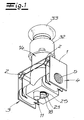
- the figures show a pump for a fluid medium, in particular for manual use in diesel-fueled internal combustion engines.
- the pump has a housing 1, which is provided with an inlet 3 and an outlet 4 is provided for the fluid medium.
- a pumping device for the fluid medium is connected to the housing 1, wherein at least one pumping state, in which the fluid medium can be conveyed by means of the pumping device, and at least one operating state, in which the fluid medium flows from the inlet 3 to the outlet 4, is adjustable.
- In the inlet 3 and outlet 4 are preferably internal thread 5, can be screwed into the line-side transition pieces.
- a first opening 7 extends over the entire cross section of the chamber.
- a circular, second opening 8 which occupies at least part of the cross-sectional area of the chamber 6.
- the second opening 8 is surrounded by a recess 23 at a radial distance.
- the Figures 2 . 3 and 4 it can be seen that the chamber 6 is connected to the inlet 3 and the outlet 4. From the Figures 2 . 3 and 4 goes on show that while the longitudinal axes L of the cylindrical inlet 3 and the cylindrical outlet 4 are superimposed.
- a sleeve 14 is movably mounted.
- the cylindrical sleeve 14 consists of a pump section 15 and a passage section 16.
- the passage section 16 is adjoined by a cylindrical centering element 18, which circumscribes a receiving groove 24.
- the sleeve 14 engages with the centering element 18 through the second opening 8 of the chamber 6 of the housing 1 and is provided with a clamping ring 25 on the sliding out of the Chamber hindered.
- the clamping ring 25 is in the embodiment in a recess 23 of the housing.
- the sleeve 14 in the FIGS. 1 . 2 and 3 shown embodiment protrudes from the first opening 7 of the chamber 6 and preferably closes off in a form-fitting manner with the inner wall of the chamber 6.
- the outer surface of the sleeve 14 is provided with at least one receiving groove for a sealing element.
- a receiving groove 20 is provided in the pump section 15 and a receiving groove 20 in the passage section 16, wherein in each case a sealing element is received in these grooves.
- the passage section 16 of the sleeve 14 has, in the exemplary embodiment, two through channels 34, 35.
- the passageways 34, 35 are perpendicular to each other and lie in one plane.
- the two passage channels 34 and 35 form in their cutting region a cutting chamber 37 which is connected by a connecting channel 17 with the pump portion 15 of the sleeve 14.
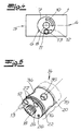
- the first passage 34 forms in the operating state together with the inlet 3 and the outlet 4, the first flow channel 38. In Fig. 2 this operating state of the pump is shown in which the first flow channel 38 is activated. In this first flow channel 38 no shut-off elements, such as valves, are arranged. By a rotation through 90 °, the first passage 34 can be pivoted out of the flow direction of the fluid medium and is then replaced by the second passage 35.
- Fig. 3 shows the pumping state in which the inlet 3 together with the second passageway 35 and the outlet 4 forms the second flow channel 39.
- a fluid medium can still be conveyed through the second flow channel 39, since the shut-off elements 36 in the direction from the inlet 3 to the outlet 4 for the fluid Medium permeable and prevent only in the opposite direction a flow.
- a rotation of the second passage 35 by 180 ° would therefore mean that no more fuel could be transported to the fuel delivery pump.
- the chamber 6 and the sleeve 14 are provided with a device which limits the angle at which the sleeve 14 can be rotated in the chamber 6 to 90 °.
- a quadrant descriptive arc-shaped groove 10 is shown, which is arranged at a radial distance adjacent to the second opening 8. In this groove 10 engages a pin 26 which is disposed adjacent to the centering element 18 of the sleeve 14. An accidental, wrong setting of the sleeve 14 is thus excluded.
- the pump is equipped with a locking device with which the sleeve 14 is held either in the pumping state or operating state.
- a recess 11 is arranged, whose edge is tapered.
- a ball 12 against the tapered edge of the recess 11, whose diameter is smaller than the diameter of the ball 12.
- a spherical segment is arranged, whose edge is tapered.
- Das Ball segment then engages positively in the recesses 27 when either the pumping state or the operating state is set.
- Fig. 2 Is the operating state set ( Fig. 2 ) engages the sleeve so that the first passage 34 connects the inlet 3 with the outlet 4.
- the first flow channel 38 thus formed is free of flow resistances which cause an undesired pressure loss.
- the first passage 34 is replaced by the second passage 35.
- Fig. 3 shows the corresponding pumping state. Now that can Pumping device to be actuated.
- the pumping device is formed by the pump section 15 of the sleeve 14, a cover 32 and a piston 28 together with the support plate 30, sealing element 31, piston rod 29 and the actuating element 33.
- the piston rod 29 is provided at one end with a thickening, which borders on the support plate 30.
- the thickening stabilizes the sealing element 31, which is pushed onto the support plate 30 and revolves around it, so that the sealing element 31 terminates in a fluid-tight manner with the inner wall of the pump section 15.
- a negative pressure is generated in the pump section 15.
- fuel flows through the inlet 3 and through the inlet-side shut-off in the second passage 35 and from there through the connecting channel 37 on the connecting passage 17 in the pump section 15, while the outlet-side shut-off closes the second passage to the exit.
Landscapes
- Engineering & Computer Science (AREA)
- Mechanical Engineering (AREA)
- General Engineering & Computer Science (AREA)
- Chemical & Material Sciences (AREA)
- Combustion & Propulsion (AREA)
- Details Of Reciprocating Pumps (AREA)
- Fuel-Injection Apparatus (AREA)
- Reciprocating Pumps (AREA)
- Rotary Pumps (AREA)
Priority Applications (11)
| Application Number | Priority Date | Filing Date | Title |
|---|---|---|---|
| DE502006004887T DE502006004887D1 (de) | 2006-11-23 | 2006-11-23 | Pumpe für ein fluides Medium, insbesondere für den manuellen Einsatz in mit Dieselkraftstoff betriebenen Brennkraftmaschinen |
| PL06024302T PL1925811T3 (pl) | 2006-11-23 | 2006-11-23 | Pompa czynnika ciekłego, zwłaszcza do ręcznego stosowania w silnikach spalinowych napędzanych olejem napędowym |
| ES06024302T ES2329279T3 (es) | 2006-11-23 | 2006-11-23 | Bomba para un medio fluido, especialmente para su utilizacion manual en motores de combustion interna que funcionan con gasoleo. |
| EP06024302A EP1925811B1 (fr) | 2006-11-23 | 2006-11-23 | Pompe pour fluide, en particulier pompe manuelle pour un moteur diesel |
| AT06024302T ATE443206T1 (de) | 2006-11-23 | 2006-11-23 | Pumpe für ein fluides medium, insbesondere für den manuellen einsatz in mit dieselkraftstoff betriebenen brennkraftmaschinen |
| JP2007298802A JP4712019B2 (ja) | 2006-11-23 | 2007-11-19 | ディーゼル燃料で動作される内燃機関の特に手動で使用するための流体媒質用のポンプ |
| KR1020070118456A KR100960910B1 (ko) | 2006-11-23 | 2007-11-20 | 유체 매체용 펌프, 특히 디젤 연료로 작동되는 내연기관에서 수동으로 사용되는 펌프 |
| US11/986,566 US7614386B2 (en) | 2006-11-23 | 2007-11-21 | Fuel pump |
| RU2007143374/06A RU2389897C2 (ru) | 2006-11-23 | 2007-11-22 | Насос для текучей среды, в частности, для ручного использования в двигателях внутреннего сгорания, работающих на дизельном топливе |
| BRPI0704212-4A BRPI0704212A (pt) | 2006-11-23 | 2007-11-22 | bomba para um meio fluido, em particular para uso manual em motores de combustão interna operados com combustìvel diesel |
| CN2007101936057A CN101187362B (zh) | 2006-11-23 | 2007-11-23 | 用于流体介质的泵 |
Applications Claiming Priority (1)
| Application Number | Priority Date | Filing Date | Title |
|---|---|---|---|
| EP06024302A EP1925811B1 (fr) | 2006-11-23 | 2006-11-23 | Pompe pour fluide, en particulier pompe manuelle pour un moteur diesel |
Publications (2)
| Publication Number | Publication Date |
|---|---|
| EP1925811A1 true EP1925811A1 (fr) | 2008-05-28 |
| EP1925811B1 EP1925811B1 (fr) | 2009-09-16 |
Family
ID=37918789
Family Applications (1)
| Application Number | Title | Priority Date | Filing Date |
|---|---|---|---|
| EP06024302A Active EP1925811B1 (fr) | 2006-11-23 | 2006-11-23 | Pompe pour fluide, en particulier pompe manuelle pour un moteur diesel |
Country Status (11)
| Country | Link |
|---|---|
| US (1) | US7614386B2 (fr) |
| EP (1) | EP1925811B1 (fr) |
| JP (1) | JP4712019B2 (fr) |
| KR (1) | KR100960910B1 (fr) |
| CN (1) | CN101187362B (fr) |
| AT (1) | ATE443206T1 (fr) |
| BR (1) | BRPI0704212A (fr) |
| DE (1) | DE502006004887D1 (fr) |
| ES (1) | ES2329279T3 (fr) |
| PL (1) | PL1925811T3 (fr) |
| RU (1) | RU2389897C2 (fr) |
Cited By (6)
| Publication number | Priority date | Publication date | Assignee | Title |
|---|---|---|---|---|
| FR2941500A1 (fr) * | 2009-01-29 | 2010-07-30 | Peugeot Citroen Automobiles Sa | Pompe d'amorcage manuelle d'un circuit d'alimentation en carburant d'un moteur a combustion |
| WO2010059576A3 (fr) * | 2008-11-18 | 2010-11-25 | Christopher Brown | Pompe-bulbe rigide d'amorçage |
| US8539922B2 (en) | 2008-02-08 | 2013-09-24 | Bluskies International, Inc. | Rigid primer bulb pump |
| US8631777B2 (en) | 2008-02-08 | 2014-01-21 | Bluskies International Llc | Rigid primer bulb pump |
| AT518014A1 (de) * | 2015-05-12 | 2017-06-15 | Anas Alaawaj | Manuelle Hubkolbenpumpe mit Dreifachrohranschluss |
| DE102012218364B4 (de) | 2012-10-09 | 2023-06-22 | Robert Bosch Gmbh | Kraftstoff-Handpumpvorrichtung |
Families Citing this family (8)
| Publication number | Priority date | Publication date | Assignee | Title |
|---|---|---|---|---|
| DE102010016480A1 (de) * | 2010-04-16 | 2011-10-20 | Hengst Gmbh & Co. Kg | Handpumpe eines Kraftstoffsystems |
| JP2011236743A (ja) * | 2010-04-30 | 2011-11-24 | Hitachi Koki Co Ltd | エンジンおよびそれを備えたエンジン作業機 |
| US20130291838A1 (en) * | 2012-05-04 | 2013-11-07 | Ronnie Lee Booth | Diesel bleeder |
| CN102817754A (zh) * | 2012-06-21 | 2012-12-12 | 张连民 | 车用柴油机燃油管进气后自动排空机构 |
| FR3022958B1 (fr) * | 2014-06-30 | 2016-07-01 | Michelin & Cie | Pompe volumetrique a piston et a moyen de distribution rotatif |
| FR3022959B1 (fr) * | 2014-06-30 | 2016-07-01 | Michelin & Cie | Pompe volumetrique a piston et procede de controle de debit associe |
| CN105651147B (zh) * | 2014-11-14 | 2018-07-24 | 陕西飞机工业(集团)有限公司 | 一种测量槽口内固定点到投影面距离的转接器及测量方法 |
| CN106988981B (zh) * | 2017-05-15 | 2019-04-19 | 广州供电局有限公司 | 手摇泵 |
Citations (5)
| Publication number | Priority date | Publication date | Assignee | Title |
|---|---|---|---|---|
| US2249326A (en) * | 1937-02-16 | 1941-07-15 | Porsche Kg | Fuel transfer pump |
| US3565555A (en) * | 1969-08-04 | 1971-02-23 | Nippodenso Kk | Manual delivery pump |
| EP0164548A2 (fr) * | 1984-06-13 | 1985-12-18 | Allied Corporation | Soupape de pompe pour séparateur de liquides |
| DE3638617A1 (de) * | 1986-11-12 | 1988-05-26 | Bosch Gmbh Robert | Fluessigkeitsfilter mit angebauter handpumpe |
| US5256040A (en) * | 1992-10-09 | 1993-10-26 | Davco Manufacturing Corp. | Priming pump valve |
Family Cites Families (11)
| Publication number | Priority date | Publication date | Assignee | Title |
|---|---|---|---|---|
| AT291759B (de) * | 1967-12-16 | 1971-07-26 | Agfa Gevaert Ag | Filmklebeeinrichtung |
| SU522337A1 (ru) * | 1974-09-12 | 1976-07-25 | Ногинский Ордена Октябрьской Революции Завод Топливной Аппаратуры Им. 50-Летия Октября | Топливоподкачивающий насос |
| SU981663A1 (ru) * | 1980-12-15 | 1982-12-15 | Центральный Научно-Исследовательский И Конструкторский Институт Топливной Аппаратуры Автотракторных И Стационарных Двигателей | Топливоподкачивающий насос дл двигател внутреннего сгорани |
| US4437986A (en) * | 1982-09-22 | 1984-03-20 | Fram Corporation | Separating device and cartridge therefor |
| SU1237784A1 (ru) * | 1984-08-28 | 1986-06-15 | Научно-производственное объединение по топливной аппаратуре двигателей "ЦНИТА" | Топливоподкачивающий насос |
| SU1285178A1 (ru) * | 1985-02-19 | 1987-01-23 | Ярославский завод дизельной аппаратуры | Топливоподкачивающий насос с ручным приводом |
| RU2071572C1 (ru) * | 1992-10-15 | 1997-01-10 | Ефим Яковлевич Мошинский | Топливный насос высокого давления |
| FR2699966A1 (fr) * | 1992-12-31 | 1994-07-01 | Sedepro | Machine à piston comportant un organe de distribution rotatif. |
| RU2153095C1 (ru) * | 1999-04-13 | 2000-07-20 | Научно-производственное предприятие "Агродизель" | Система топливоподачи дизеля |
| CN1153903C (zh) * | 2002-05-11 | 2004-06-16 | 易斌 | 一种柴油发动机燃油输油泵 |
| US7431575B2 (en) * | 2005-01-21 | 2008-10-07 | Cummins Filtration Ip, Inc. | Auto valve priming pump |
-
2006
- 2006-11-23 PL PL06024302T patent/PL1925811T3/pl unknown
- 2006-11-23 ES ES06024302T patent/ES2329279T3/es active Active
- 2006-11-23 DE DE502006004887T patent/DE502006004887D1/de active Active
- 2006-11-23 EP EP06024302A patent/EP1925811B1/fr active Active
- 2006-11-23 AT AT06024302T patent/ATE443206T1/de active
-
2007
- 2007-11-19 JP JP2007298802A patent/JP4712019B2/ja not_active Expired - Fee Related
- 2007-11-20 KR KR1020070118456A patent/KR100960910B1/ko not_active Expired - Fee Related
- 2007-11-21 US US11/986,566 patent/US7614386B2/en not_active Expired - Fee Related
- 2007-11-22 BR BRPI0704212-4A patent/BRPI0704212A/pt not_active IP Right Cessation
- 2007-11-22 RU RU2007143374/06A patent/RU2389897C2/ru not_active IP Right Cessation
- 2007-11-23 CN CN2007101936057A patent/CN101187362B/zh not_active Expired - Fee Related
Patent Citations (5)
| Publication number | Priority date | Publication date | Assignee | Title |
|---|---|---|---|---|
| US2249326A (en) * | 1937-02-16 | 1941-07-15 | Porsche Kg | Fuel transfer pump |
| US3565555A (en) * | 1969-08-04 | 1971-02-23 | Nippodenso Kk | Manual delivery pump |
| EP0164548A2 (fr) * | 1984-06-13 | 1985-12-18 | Allied Corporation | Soupape de pompe pour séparateur de liquides |
| DE3638617A1 (de) * | 1986-11-12 | 1988-05-26 | Bosch Gmbh Robert | Fluessigkeitsfilter mit angebauter handpumpe |
| US5256040A (en) * | 1992-10-09 | 1993-10-26 | Davco Manufacturing Corp. | Priming pump valve |
Cited By (8)
| Publication number | Priority date | Publication date | Assignee | Title |
|---|---|---|---|---|
| US8069830B2 (en) | 2008-02-08 | 2011-12-06 | Christopher Brown | Rigid primer bulb pump |
| US8539922B2 (en) | 2008-02-08 | 2013-09-24 | Bluskies International, Inc. | Rigid primer bulb pump |
| US8631777B2 (en) | 2008-02-08 | 2014-01-21 | Bluskies International Llc | Rigid primer bulb pump |
| WO2010059576A3 (fr) * | 2008-11-18 | 2010-11-25 | Christopher Brown | Pompe-bulbe rigide d'amorçage |
| FR2941500A1 (fr) * | 2009-01-29 | 2010-07-30 | Peugeot Citroen Automobiles Sa | Pompe d'amorcage manuelle d'un circuit d'alimentation en carburant d'un moteur a combustion |
| DE102012218364B4 (de) | 2012-10-09 | 2023-06-22 | Robert Bosch Gmbh | Kraftstoff-Handpumpvorrichtung |
| AT518014A1 (de) * | 2015-05-12 | 2017-06-15 | Anas Alaawaj | Manuelle Hubkolbenpumpe mit Dreifachrohranschluss |
| AT518014B1 (de) * | 2015-05-12 | 2020-08-15 | Anas Alaawaj | Manuelle Hubkolbenpumpe mit Dreifachrohranschluss |
Also Published As
| Publication number | Publication date |
|---|---|
| US7614386B2 (en) | 2009-11-10 |
| BRPI0704212A (pt) | 2008-07-15 |
| KR20080047275A (ko) | 2008-05-28 |
| EP1925811B1 (fr) | 2009-09-16 |
| CN101187362B (zh) | 2013-09-11 |
| RU2007143374A (ru) | 2009-05-27 |
| CN101187362A (zh) | 2008-05-28 |
| JP4712019B2 (ja) | 2011-06-29 |
| PL1925811T3 (pl) | 2010-02-26 |
| RU2389897C2 (ru) | 2010-05-20 |
| ATE443206T1 (de) | 2009-10-15 |
| US20080135008A1 (en) | 2008-06-12 |
| ES2329279T3 (es) | 2009-11-24 |
| KR100960910B1 (ko) | 2010-06-04 |
| DE502006004887D1 (de) | 2009-10-29 |
| JP2008128243A (ja) | 2008-06-05 |
Similar Documents
| Publication | Publication Date | Title |
|---|---|---|
| EP1925811B1 (fr) | Pompe pour fluide, en particulier pompe manuelle pour un moteur diesel | |
| DE3010613C2 (fr) | ||
| DE102008057666B4 (de) | Leckfreie Kartusche mit ovaler Dichtung | |
| DE2933512C2 (de) | Proben-Einspritzventil | |
| DE102009026172A1 (de) | Mehrweghahn und Verfahren zu dessen Herstellung | |
| DE1476673A1 (de) | Pumpe | |
| DE8308036U1 (de) | Haltevorrichtung fuer das kraftstoffeinspritzventil eines dieselmotors | |
| EP1636483B1 (fr) | Soupape permettant de commander le passage de liquides | |
| DE1291451B (de) | Mischvorrichtung zur Erzeugung von Heisswasser | |
| DE102009008818B4 (de) | Handpumpe zum Pumpen von Kraftstoff | |
| DE19529197A1 (de) | Entleerventil | |
| DE102011007781A1 (de) | Steckpumpe | |
| EP1088985A2 (fr) | Injecteur de carburant pour injection directe dans un moteur à combustion interne | |
| DE29610765U1 (de) | Anschlußvorrichtung für Kraftstoffleitungen eines Kraftfahrzeuges | |
| DE102013211147B4 (de) | Niederdruckkreis einer Kraftstofffördereinrichtung eines Kraftstoffeinspritzsystems | |
| DE10305394B4 (de) | Flüssigkeitsventil für Heiz- und/oder Kühlanlagen | |
| DE112017004272B4 (de) | Überdruckventilvorrichtung und hochdruckpumpe | |
| DE2240012C3 (de) | Steuereinrichtung für hydrostatische Hilfskraftlenkungen o.dgl. | |
| DE19852409A1 (de) | Druckbegrenzungsventil, insbesondere für Fahrzeuge | |
| DE4320925A1 (de) | Druckregler für Kraftstoff-Einspritzanlagen | |
| EP2644789B1 (fr) | Ensemble modulaire d'un agencement de séparation de tuyaux | |
| EP3379118A1 (fr) | Clapet anti-retour | |
| DE69212014T2 (de) | Manuell und pneumatisch betätigbare Absperrarmatur | |
| DE856265C (de) | Umschaltvorrichtung fuer Kraftstoff-Haupt- und -Reserveleitung von Kraftfahrzeugen | |
| WO2025103790A1 (fr) | Clapet anti-retour et distributeur doté d'un clapet anti-retour |
Legal Events
| Date | Code | Title | Description |
|---|---|---|---|
| PUAI | Public reference made under article 153(3) epc to a published international application that has entered the european phase |
Free format text: ORIGINAL CODE: 0009012 |
|
| AK | Designated contracting states |
Kind code of ref document: A1 Designated state(s): AT BE BG CH CY CZ DE DK EE ES FI FR GB GR HU IE IS IT LI LT LU LV MC NL PL PT RO SE SI SK TR |
|
| AX | Request for extension of the european patent |
Extension state: AL BA HR MK RS |
|
| 17P | Request for examination filed |
Effective date: 20080506 |
|
| AKX | Designation fees paid |
Designated state(s): AT BE BG CH CY CZ DE DK EE ES FI FR GB GR HU IE IS IT LI LT LU LV MC NL PL PT RO SE SI SK TR |
|
| AXX | Extension fees paid |
Extension state: AL Payment date: 20080628 Extension state: MK Payment date: 20080628 Extension state: RS Payment date: 20080628 Extension state: BA Payment date: 20080628 Extension state: HR Payment date: 20080628 |
|
| GRAP | Despatch of communication of intention to grant a patent |
Free format text: ORIGINAL CODE: EPIDOSNIGR1 |
|
| GRAS | Grant fee paid |
Free format text: ORIGINAL CODE: EPIDOSNIGR3 |
|
| GRAA | (expected) grant |
Free format text: ORIGINAL CODE: 0009210 |
|
| AK | Designated contracting states |
Kind code of ref document: B1 Designated state(s): AT BE BG CH CY CZ DE DK EE ES FI FR GB GR HU IE IS IT LI LT LU LV MC NL PL PT RO SE SI SK TR |
|
| AX | Request for extension of the european patent |
Extension state: AL BA HR MK RS |
|
| REG | Reference to a national code |
Ref country code: GB Ref legal event code: FG4D Free format text: NOT ENGLISH |
|
| REG | Reference to a national code |
Ref country code: CH Ref legal event code: EP |
|
| REG | Reference to a national code |
Ref country code: IE Ref legal event code: FG4D |
|
| REF | Corresponds to: |
Ref document number: 502006004887 Country of ref document: DE Date of ref document: 20091029 Kind code of ref document: P |
|
| REG | Reference to a national code |
Ref country code: ES Ref legal event code: FG2A Ref document number: 2329279 Country of ref document: ES Kind code of ref document: T3 |
|
| PG25 | Lapsed in a contracting state [announced via postgrant information from national office to epo] |
Ref country code: LT Free format text: LAPSE BECAUSE OF FAILURE TO SUBMIT A TRANSLATION OF THE DESCRIPTION OR TO PAY THE FEE WITHIN THE PRESCRIBED TIME-LIMIT Effective date: 20090916 Ref country code: FI Free format text: LAPSE BECAUSE OF FAILURE TO SUBMIT A TRANSLATION OF THE DESCRIPTION OR TO PAY THE FEE WITHIN THE PRESCRIBED TIME-LIMIT Effective date: 20090916 Ref country code: SE Free format text: LAPSE BECAUSE OF FAILURE TO SUBMIT A TRANSLATION OF THE DESCRIPTION OR TO PAY THE FEE WITHIN THE PRESCRIBED TIME-LIMIT Effective date: 20090916 |
|
| LTIE | Lt: invalidation of european patent or patent extension |
Effective date: 20090916 |
|
| PG25 | Lapsed in a contracting state [announced via postgrant information from national office to epo] |
Ref country code: LV Free format text: LAPSE BECAUSE OF FAILURE TO SUBMIT A TRANSLATION OF THE DESCRIPTION OR TO PAY THE FEE WITHIN THE PRESCRIBED TIME-LIMIT Effective date: 20090916 Ref country code: SI Free format text: LAPSE BECAUSE OF FAILURE TO SUBMIT A TRANSLATION OF THE DESCRIPTION OR TO PAY THE FEE WITHIN THE PRESCRIBED TIME-LIMIT Effective date: 20090916 Ref country code: NL Free format text: LAPSE BECAUSE OF FAILURE TO SUBMIT A TRANSLATION OF THE DESCRIPTION OR TO PAY THE FEE WITHIN THE PRESCRIBED TIME-LIMIT Effective date: 20090916 |
|
| REG | Reference to a national code |
Ref country code: PL Ref legal event code: T3 |
|
| NLV1 | Nl: lapsed or annulled due to failure to fulfill the requirements of art. 29p and 29m of the patents act | ||
| PG25 | Lapsed in a contracting state [announced via postgrant information from national office to epo] |
Ref country code: CY Free format text: LAPSE BECAUSE OF FAILURE TO SUBMIT A TRANSLATION OF THE DESCRIPTION OR TO PAY THE FEE WITHIN THE PRESCRIBED TIME-LIMIT Effective date: 20090916 |
|
| REG | Reference to a national code |
Ref country code: IE Ref legal event code: FD4D |
|
| PG25 | Lapsed in a contracting state [announced via postgrant information from national office to epo] |
Ref country code: IS Free format text: LAPSE BECAUSE OF FAILURE TO SUBMIT A TRANSLATION OF THE DESCRIPTION OR TO PAY THE FEE WITHIN THE PRESCRIBED TIME-LIMIT Effective date: 20100116 Ref country code: RO Free format text: LAPSE BECAUSE OF FAILURE TO SUBMIT A TRANSLATION OF THE DESCRIPTION OR TO PAY THE FEE WITHIN THE PRESCRIBED TIME-LIMIT Effective date: 20090916 Ref country code: IE Free format text: LAPSE BECAUSE OF FAILURE TO SUBMIT A TRANSLATION OF THE DESCRIPTION OR TO PAY THE FEE WITHIN THE PRESCRIBED TIME-LIMIT Effective date: 20090916 Ref country code: EE Free format text: LAPSE BECAUSE OF FAILURE TO SUBMIT A TRANSLATION OF THE DESCRIPTION OR TO PAY THE FEE WITHIN THE PRESCRIBED TIME-LIMIT Effective date: 20090916 Ref country code: PT Free format text: LAPSE BECAUSE OF FAILURE TO SUBMIT A TRANSLATION OF THE DESCRIPTION OR TO PAY THE FEE WITHIN THE PRESCRIBED TIME-LIMIT Effective date: 20100118 Ref country code: CZ Free format text: LAPSE BECAUSE OF FAILURE TO SUBMIT A TRANSLATION OF THE DESCRIPTION OR TO PAY THE FEE WITHIN THE PRESCRIBED TIME-LIMIT Effective date: 20090916 |
|
| BERE | Be: lapsed |
Owner name: WILLIBRORD LOSING FILTERPRODUKTION G.M.B.H. Effective date: 20091130 |
|
| PG25 | Lapsed in a contracting state [announced via postgrant information from national office to epo] |
Ref country code: SK Free format text: LAPSE BECAUSE OF FAILURE TO SUBMIT A TRANSLATION OF THE DESCRIPTION OR TO PAY THE FEE WITHIN THE PRESCRIBED TIME-LIMIT Effective date: 20090916 |
|
| PG25 | Lapsed in a contracting state [announced via postgrant information from national office to epo] |
Ref country code: MC Free format text: LAPSE BECAUSE OF NON-PAYMENT OF DUE FEES Effective date: 20091130 |
|
| PLBE | No opposition filed within time limit |
Free format text: ORIGINAL CODE: 0009261 |
|
| STAA | Information on the status of an ep patent application or granted ep patent |
Free format text: STATUS: NO OPPOSITION FILED WITHIN TIME LIMIT |
|
| PG25 | Lapsed in a contracting state [announced via postgrant information from national office to epo] |
Ref country code: DK Free format text: LAPSE BECAUSE OF FAILURE TO SUBMIT A TRANSLATION OF THE DESCRIPTION OR TO PAY THE FEE WITHIN THE PRESCRIBED TIME-LIMIT Effective date: 20090916 |
|
| 26N | No opposition filed |
Effective date: 20100617 |
|
| PG25 | Lapsed in a contracting state [announced via postgrant information from national office to epo] |
Ref country code: BE Free format text: LAPSE BECAUSE OF NON-PAYMENT OF DUE FEES Effective date: 20091130 Ref country code: GR Free format text: LAPSE BECAUSE OF FAILURE TO SUBMIT A TRANSLATION OF THE DESCRIPTION OR TO PAY THE FEE WITHIN THE PRESCRIBED TIME-LIMIT Effective date: 20091217 |
|
| REG | Reference to a national code |
Ref country code: ES Ref legal event code: FD2A Effective date: 20110302 |
|
| PG25 | Lapsed in a contracting state [announced via postgrant information from national office to epo] |
Ref country code: BG Free format text: LAPSE BECAUSE OF FAILURE TO SUBMIT A TRANSLATION OF THE DESCRIPTION OR TO PAY THE FEE WITHIN THE PRESCRIBED TIME-LIMIT Effective date: 20091130 |
|
| PG25 | Lapsed in a contracting state [announced via postgrant information from national office to epo] |
Ref country code: LU Free format text: LAPSE BECAUSE OF NON-PAYMENT OF DUE FEES Effective date: 20091123 |
|
| PG25 | Lapsed in a contracting state [announced via postgrant information from national office to epo] |
Ref country code: HU Free format text: LAPSE BECAUSE OF FAILURE TO SUBMIT A TRANSLATION OF THE DESCRIPTION OR TO PAY THE FEE WITHIN THE PRESCRIBED TIME-LIMIT Effective date: 20100317 |
|
| REG | Reference to a national code |
Ref country code: CH Ref legal event code: PL |
|
| PG25 | Lapsed in a contracting state [announced via postgrant information from national office to epo] |
Ref country code: CH Free format text: LAPSE BECAUSE OF NON-PAYMENT OF DUE FEES Effective date: 20101130 Ref country code: ES Free format text: LAPSE BECAUSE OF NON-PAYMENT OF DUE FEES Effective date: 20110301 Ref country code: LI Free format text: LAPSE BECAUSE OF NON-PAYMENT OF DUE FEES Effective date: 20101130 |
|
| PG25 | Lapsed in a contracting state [announced via postgrant information from national office to epo] |
Ref country code: ES Free format text: LAPSE BECAUSE OF NON-PAYMENT OF DUE FEES Effective date: 20091124 |
|
| PGFP | Annual fee paid to national office [announced via postgrant information from national office to epo] |
Ref country code: AT Payment date: 20131113 Year of fee payment: 8 Ref country code: DE Payment date: 20131112 Year of fee payment: 8 Ref country code: GB Payment date: 20131120 Year of fee payment: 8 Ref country code: FR Payment date: 20131120 Year of fee payment: 8 |
|
| PGFP | Annual fee paid to national office [announced via postgrant information from national office to epo] |
Ref country code: TR Payment date: 20131030 Year of fee payment: 8 Ref country code: IT Payment date: 20131126 Year of fee payment: 8 Ref country code: ES Payment date: 20131125 Year of fee payment: 8 Ref country code: PL Payment date: 20131025 Year of fee payment: 8 |
|
| REG | Reference to a national code |
Ref country code: DE Ref legal event code: R119 Ref document number: 502006004887 Country of ref document: DE |
|
| REG | Reference to a national code |
Ref country code: AT Ref legal event code: MM01 Ref document number: 443206 Country of ref document: AT Kind code of ref document: T Effective date: 20141123 |
|
| GBPC | Gb: european patent ceased through non-payment of renewal fee |
Effective date: 20141123 |
|
| REG | Reference to a national code |
Ref country code: FR Ref legal event code: ST Effective date: 20150731 |
|
| PG25 | Lapsed in a contracting state [announced via postgrant information from national office to epo] |
Ref country code: AT Free format text: LAPSE BECAUSE OF NON-PAYMENT OF DUE FEES Effective date: 20141123 |
|
| PG25 | Lapsed in a contracting state [announced via postgrant information from national office to epo] |
Ref country code: GB Free format text: LAPSE BECAUSE OF NON-PAYMENT OF DUE FEES Effective date: 20141123 Ref country code: DE Free format text: LAPSE BECAUSE OF NON-PAYMENT OF DUE FEES Effective date: 20150602 |
|
| PG25 | Lapsed in a contracting state [announced via postgrant information from national office to epo] |
Ref country code: FR Free format text: LAPSE BECAUSE OF NON-PAYMENT OF DUE FEES Effective date: 20141201 |
|
| REG | Reference to a national code |
Ref country code: ES Ref legal event code: FD2A Effective date: 20151229 |
|
| PG25 | Lapsed in a contracting state [announced via postgrant information from national office to epo] |
Ref country code: IT Free format text: LAPSE BECAUSE OF NON-PAYMENT OF DUE FEES Effective date: 20141123 |
|
| PG25 | Lapsed in a contracting state [announced via postgrant information from national office to epo] |
Ref country code: ES Free format text: LAPSE BECAUSE OF NON-PAYMENT OF DUE FEES Effective date: 20141124 Ref country code: PL Free format text: LAPSE BECAUSE OF NON-PAYMENT OF DUE FEES Effective date: 20141123 |
|
| PG25 | Lapsed in a contracting state [announced via postgrant information from national office to epo] |
Ref country code: TR Free format text: LAPSE BECAUSE OF NON-PAYMENT OF DUE FEES Effective date: 20141123 |