EP1926009A2 - Capteur d'activation - Google Patents
Capteur d'activation Download PDFInfo
- Publication number
- EP1926009A2 EP1926009A2 EP20070253494 EP07253494A EP1926009A2 EP 1926009 A2 EP1926009 A2 EP 1926009A2 EP 20070253494 EP20070253494 EP 20070253494 EP 07253494 A EP07253494 A EP 07253494A EP 1926009 A2 EP1926009 A2 EP 1926009A2
- Authority
- EP
- European Patent Office
- Prior art keywords
- trigger signal
- signal
- arrangement
- bleed valve
- threshold
- Prior art date
- Legal status (The legal status is an assumption and is not a legal conclusion. Google has not performed a legal analysis and makes no representation as to the accuracy of the status listed.)
- Granted
Links
- 230000004913 activation Effects 0.000 title claims abstract description 28
- 230000004044 response Effects 0.000 claims abstract description 51
- 238000000034 method Methods 0.000 claims description 28
- VIKNJXKGJWUCNN-XGXHKTLJSA-N norethisterone Chemical compound O=C1CC[C@@H]2[C@H]3CC[C@](C)([C@](CC4)(O)C#C)[C@@H]4[C@@H]3CCC2=C1 VIKNJXKGJWUCNN-XGXHKTLJSA-N 0.000 claims description 7
- 238000012790 confirmation Methods 0.000 claims description 5
- 230000001419 dependent effect Effects 0.000 claims description 5
- 238000012360 testing method Methods 0.000 abstract description 15
- 230000000694 effects Effects 0.000 abstract description 4
- 238000012935 Averaging Methods 0.000 abstract description 3
- 238000012545 processing Methods 0.000 abstract description 3
- 238000001914 filtration Methods 0.000 description 11
- 238000013459 approach Methods 0.000 description 6
- 230000008859 change Effects 0.000 description 5
- 238000012544 monitoring process Methods 0.000 description 5
- 230000001052 transient effect Effects 0.000 description 4
- 230000001143 conditioned effect Effects 0.000 description 3
- 230000010006 flight Effects 0.000 description 3
- 230000001141 propulsive effect Effects 0.000 description 3
- 230000009467 reduction Effects 0.000 description 3
- 230000003750 conditioning effect Effects 0.000 description 2
- 238000001514 detection method Methods 0.000 description 2
- 230000004069 differentiation Effects 0.000 description 2
- 239000012530 fluid Substances 0.000 description 2
- 230000033001 locomotion Effects 0.000 description 2
- 230000008569 process Effects 0.000 description 2
- 238000004364 calculation method Methods 0.000 description 1
- 238000002485 combustion reaction Methods 0.000 description 1
- 230000006835 compression Effects 0.000 description 1
- 238000007906 compression Methods 0.000 description 1
- 238000011217 control strategy Methods 0.000 description 1
- 238000013461 design Methods 0.000 description 1
- 239000000446 fuel Substances 0.000 description 1
- 238000012423 maintenance Methods 0.000 description 1
- 239000000203 mixture Substances 0.000 description 1
- 230000001151 other effect Effects 0.000 description 1
- 230000008439 repair process Effects 0.000 description 1
- 238000005070 sampling Methods 0.000 description 1
- 230000006641 stabilisation Effects 0.000 description 1
- 239000000126 substance Substances 0.000 description 1
Images

Classifications
-
- F—MECHANICAL ENGINEERING; LIGHTING; HEATING; WEAPONS; BLASTING
- F01—MACHINES OR ENGINES IN GENERAL; ENGINE PLANTS IN GENERAL; STEAM ENGINES
- F01D—NON-POSITIVE DISPLACEMENT MACHINES OR ENGINES, e.g. STEAM TURBINES
- F01D17/00—Regulating or controlling by varying flow
- F01D17/20—Devices dealing with sensing elements or final actuators or transmitting means between them, e.g. power-assisted
-
- F—MECHANICAL ENGINEERING; LIGHTING; HEATING; WEAPONS; BLASTING
- F02—COMBUSTION ENGINES; HOT-GAS OR COMBUSTION-PRODUCT ENGINE PLANTS
- F02C—GAS-TURBINE PLANTS; AIR INTAKES FOR JET-PROPULSION PLANTS; CONTROLLING FUEL SUPPLY IN AIR-BREATHING JET-PROPULSION PLANTS
- F02C9/00—Controlling gas-turbine plants; Controlling fuel supply in air- breathing jet-propulsion plants
- F02C9/16—Control of working fluid flow
- F02C9/18—Control of working fluid flow by bleeding, bypassing or acting on variable working fluid interconnections between turbines or compressors or their stages
-
- Y—GENERAL TAGGING OF NEW TECHNOLOGICAL DEVELOPMENTS; GENERAL TAGGING OF CROSS-SECTIONAL TECHNOLOGIES SPANNING OVER SEVERAL SECTIONS OF THE IPC; TECHNICAL SUBJECTS COVERED BY FORMER USPC CROSS-REFERENCE ART COLLECTIONS [XRACs] AND DIGESTS
- Y02—TECHNOLOGIES OR APPLICATIONS FOR MITIGATION OR ADAPTATION AGAINST CLIMATE CHANGE
- Y02T—CLIMATE CHANGE MITIGATION TECHNOLOGIES RELATED TO TRANSPORTATION
- Y02T50/00—Aeronautics or air transport
- Y02T50/60—Efficient propulsion technologies, e.g. for aircraft
-
- Y—GENERAL TAGGING OF NEW TECHNOLOGICAL DEVELOPMENTS; GENERAL TAGGING OF CROSS-SECTIONAL TECHNOLOGIES SPANNING OVER SEVERAL SECTIONS OF THE IPC; TECHNICAL SUBJECTS COVERED BY FORMER USPC CROSS-REFERENCE ART COLLECTIONS [XRACs] AND DIGESTS
- Y10—TECHNICAL SUBJECTS COVERED BY FORMER USPC
- Y10T—TECHNICAL SUBJECTS COVERED BY FORMER US CLASSIFICATION
- Y10T137/00—Fluid handling
- Y10T137/8158—With indicator, register, recorder, alarm or inspection means
- Y10T137/8175—Plural
-
- Y—GENERAL TAGGING OF NEW TECHNOLOGICAL DEVELOPMENTS; GENERAL TAGGING OF CROSS-SECTIONAL TECHNOLOGIES SPANNING OVER SEVERAL SECTIONS OF THE IPC; TECHNICAL SUBJECTS COVERED BY FORMER USPC CROSS-REFERENCE ART COLLECTIONS [XRACs] AND DIGESTS
- Y10—TECHNICAL SUBJECTS COVERED BY FORMER USPC
- Y10T—TECHNICAL SUBJECTS COVERED BY FORMER US CLASSIFICATION
- Y10T137/00—Fluid handling
- Y10T137/8158—With indicator, register, recorder, alarm or inspection means
- Y10T137/8326—Fluid pressure responsive indicator, recorder or alarm
Definitions
- the present invention relates to activation sensing and more particularly to activation sensing to determine activation of a bleed valve particularly in high pressure or intermediate pressure compressor stages of a gas turbine engine.
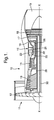
- a gas turbine engine is generally indicated at 10 and comprises, in axial flow series, an air intake 11, a propulsive fan 12, an intermediate pressure compressor 13, a high pressure compressor 14, a combustor 15, a turbine arrangement comprising a high pressure turbine 16, an intermediate pressure turbine 17 and a low pressure turbine 18, and an exhaust nozzle 19.
- the gas turbine engine 10 operates in a conventional manner so that air entering the intake 11 is accelerated by the fan 12 which produce two air flows: a first air flow into the intermediate pressure compressor 13 and a second air flow which provides propulsive thrust.
- the intermediate pressure compressor compresses the air flow directed into it before delivering that air to the high pressure compressor 14 where further compression takes place.
- the compressed air exhausted from the high pressure compressor 14 is directed into the combustor 15 where it is mixed with fuel and the mixture combusted.
- the resultant hot combustion products then expand through, and thereby drive, the high, intermediate and low pressure turbines 16, 17 and 18 before being exhausted through the nozzle 19 to provide additional propulsive thrust.
- the high, intermediate and low pressure turbines 16, 17 and 18 respectively drive the high and intermediate pressure compressors 14 and 13 and the fan 12 by suitable interconnecting shafts.
- An example of a prior indirect approach to determine bleed valve operation includes a specific test of bleed valve operation carried out at least once per flight during descent whilst the engine is idle. Thus, a sensor for compressor pressure is monitored for a period, typically 0.5 seconds, then a bleed valve is opened. The compressor pressure is then monitored for a further period of up to 1.5 seconds or until the required change in the compressor pressure is observed indicating that a valve has opened. If the desired time passes without the required change in the compressor pressure being observed, the valve is deemed not to have opened. If the valve opening test is passed the closing test is performed in a similar way, that is to say waiting for a period of typically 10 seconds until the compressor pressure has stabilised.
- an activation sensor arrangement for a bleed valve comprising a sensor for flow pressure and a non linear signal filter to accentuate a response signal from the sensor to provide a trigger signal and a monitor to receive the trigger signal for comparison with a threshold and provide an activation indicator if the trigger signal exceeds the threshold.
- the trigger signal comprises an averaged number of sampled values determined by the sensor for flow pressure.
- the flow pressure is defined by compressor exit pressure at the high pressure or intermediate pressure stages of a gas turbine engine.
- the flow pressure is the compressor exit pressure from the high pressure compressor stage of the engine whether the bleed valve is associated with the high pressure compressor or the intermediate pressure compressor.
- the trigger signal is determined over a time period.
- the non linear signal filter is arranged to accentuate variations in the trigger signal greater than and/or less than a pre determined time period.
- the pre determined time period is greater than 300 milli seconds.
- the monitor determines a gradient in the trigger signal over a signal time window.
- the monitor provides a lower threshold and an upper threshold, the lower threshold indicative of a possible switching of the bleed valve whilst the upper threshold provides confirmation that the bleed valve has been activated.
- the senor provides a continuous output as the response signal.
- the non linear signal filter provides a continuous output trigger signal.
- the control monitors the continuous output trigger signal to provide an activation indicator only when that continuous output trigger signal exceeds the threshold indicative of bleed valve operation.
- the non-linear signal filter allows comparison with the threshold when the trigger signal has undulations which have a variable frequency.
- a method of determining bleed valve activation in a gas turbine engine comprising:
- comparison of the trigger signal is provided over a predetermined time period.
- the non linear signal filter acts to accentuate response signals having a time period in excess of a predetermined time period.
- the predetermined time period is greater than 300 milli seconds.
- the pressure value is taken from an intermediate pressure stage or a high pressure stage of the gas turbine engine.
- the method comprises providing two thresholds, a lower threshold indicative of possible bleed valve operation and a higher threshold indicative of bleed valve operation.
- the method applies a non-linear filter to provide the trigger signal when the trigger signal has undulations which have a frequency which is variable.
- a bleed valve open status is indicated by a 1 on the graphic Y1 of control signal status which causes the changes in the sensed pressure value 99 in the flow pressure value scale Y2.
- a closed bleed valve is indicated by a 0 on the scale Y1.
- control signal status 100 indicates an open valve command which can rapidly change to a closed control signal status 111.
- the control signals 100, 111 are provided by a central controller as required for operation of a system incorporated in the bleed valve.
- the pressure value 99 as determined by a sensor will be in a "hump" period 99a.
- the gradients and time periods of the "hump" period are characteristic of the change between the valve open to valve closed flow pressure values and will be dependent upon engine type and power output level. Nevertheless, such a transient hump period will be noticeable and characteristic of bleed valve operation, that is to say open to closed, or closed to open. It will be understood that the converse of closing the valve will be opening of the valve and this will be substantially reflected in an inversion of the graphical depiction of Fig. 2.
- a non linear filtering approach is utilised in order to provide a target signal value for comparison with the thresholds.
- a signal taken from a flow pressure sensor is averaged, filtered and differentiated in order to provide a conditioned differential response signal with suitable filtering to ensure attenuation of any high frequency noise within the response from a sensor.
- filtering with a first order lag with a time constant of 25 milli seconds and differentiation of the signal to create the conditioned differential response signal as indicated suitably filtered to ensure attenuation of high frequency noise.
- Fig. 3 provides a graphic illustration of a response signal 21 filtered against time and pressure YY2 whilst valve control signal status 22 is plotted against a valve position scale YY1.
- a peak 21a provides an indication with regard to bleed valve opening and closing.
- a dip 21b is a product of the processing of the response signal 21 from the raw sensor signal values 99 and in particular the "hump" period portion of the sensor signal values as depicted in Fig. 2.
- the whole peak 21a, 21b is used.
- the whole signal in the window is used by virtue of the fact that the processing is substantially continuous. However, it is only the peak 21a that is of particularly interest.
- the dip 21b is part of the control system response and is much shallower than the engine response, that is to say peak 21a and hence we can distinguish one from the other.
- the design could be sensitive to engine response, that is to say peak 21a and not sensitive to the control system response, that is to say dip 21b.
- DelX can be tuned to different expected frequency responses and/or different update rates.
- the trigger signal may be optimised for a variable frequency trigger signal.
- DelX is derived from a signal response and typically taken from an existing flow pressure sensor and appropriately manipulated to create a response signal in accordance with the requirements of the present invention. In such circumstances, DelX is effectively continuously calculated whether or not a bleed valve is operated. In such circumstances DelX can therefore be used for other forms of detection and protection including surge protection. However, it will be understood that the provision of an appropriate filtered response is in fact typically an existing response which can be utilised in accordance with aspects of the present invention.
- substantially continuous will be understood to mean that if DelX is considered in theoretical terms then it can be considered a continuous function as undulating occurs so frequently. However, the processes to determine Del will calculate Del every 25ms which means that in terms of a strict interpretation DelX in use is discontinuous and moreover discreet. However, by reference to being substantially continuous, in such circumstances in accordance with aspects of the present invention was calculated on every situation, not just those near to a bleed valve switch operation and in that sense is continuously calculated rather than continuous in itself.
- DelX in accordance with aspects of the present invention is looked at in a time window following a bleed valve operation or command. It will also be understood that as indicated above it is filtering of the response signal in order to create an appropriate trigger signal which is important with regard to the present invention. In addition to determining Del in a time window following command it will also be understood that other factors in addition to time may be added, thus it may be possible to look at trigger signal not only in a time window from bleed valve operation or demand but also in terms of maximum perturbation from a response signal.
- this non-linear filter is to accentuate changes in the sensed pressure value which are consistent with valve operation. Changes to be accentuated will have a time period of generally around 300ms.
- the filter acts to de-emphasise any higher frequency effects which are considered noise and cancel out any inherent longer trends or features due to engine operation and transients.
- the non-linear filter acts to emphasise response signals having time periods indicative of valve operation. These time periods may be greater than a pre-determined time period, less than a pre-determined time period or in a range of time periods dependent upon valve characteristics and the potential for other causes of flow pressure perturbations.
- the filter emphasises trends in the response signal for the previous 150ms and subtracts it from the gradient for the 150ms prior to that.
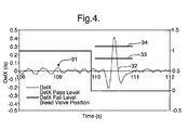
- thresholds 33, 34 with a peak or trough in the target signal 31 to indicate whether a bleed valve has been switched when commanded.
- several bleed valves may be operated sequentially and therefore it is possible as indicated to determine thresholds for target value signals for each individual bleed valve operated or generally for all valves. In such circumstances, in Fig. 4 it will be understood if the deviation of the target response trace 31 exceeds a higher threshold 34 then this indicates correct switching of the bleed valve. If the deflection in the response signal 31 fails to exceed the lower threshold 33, then this indicates that the bleed valve has failed to switch.
- the method of aspects of the present invention requires monitoring of flow pressure values through an appropriate sensor and then initially averaging, filtering and differentiating those raw flow pressure response values to provide a response value for accentuating through a non-linear filter to provide a target signal trace which is then compared with at least one threshold and typically two thresholds to determine bleed valve operation.
- the present method and an apparatus to perform it utilises normal switching of bleed valves to observe their correct operation.
- Such use of normal switching of the bleed valves will reduce wear and tear upon the bleed valves in comparison with previous approaches which required additional valve switching purely for testing.
- This test switching of the bleed valves further required particular operational conditions for valve operation determination which as indicated above may be difficult to provide during normal engine operation.
- the present approach to monitoring activation could be utilised with a dedicated ground test regime for an engine.
- the target signal value produced by the non-linear filtering in accordance with aspects of the present invention essentially decouples through the algorithmic relationship described above basic operational variations in the basic pressure signal value as determined by a sensor. In such circumstances it is not necessary to achieve a steady state with regard to stable pressure values in accordance with previous systems in order to ensure that variations are due to valve operation. It will be understood in normal bleed valve systems close or simultaneous valve operation of two or more valves will not be recommended. However, should such close switching occur the peaks may merge in DelX so that surety with regard to whether the response is due to one or both valves is difficult, that is to say it is difficult to determine whether both valves are operating although it may be possible to determine at least one valve has operated. By use of operational results taken over one or a number of flights, it will be appreciated that correct operation of the valves can be confirmed at least over a number of flights as there will be an adequate number of discernible determinations.
- the present method operates on all flight phases, that is to say, engine operational conditions, whenever a bleed valve is switched.
- the present method and apparatus does not rely upon any assumption as to throttle manipulation or flight condition.
- normal flight operations will achieve adequate results with respect to determining bleed valve operation.
- increasing the amount of throttle movement beyond a normal amount would result in an increased number of bleed valve switchings and thus, greater identification of such switchings in the target response signals provided to increase the presumptive accuracy of such switching.
- greater reliability can be accorded to successfully monitoring bleed valve operation. Such greater reliability may improve the ability to detect failures which could overheat the nacelle structure. Furthermore, detection of bleed valve operation is needed in order to provide improved certainty with respect to dissipation of energy in cases of a shaftbreak. Thus, greater reliability with respect to bleed valve operation may allow a reduction in the inertia and therefore the mass of the rotating components. In aircraft applications, it will be understood that a reduction in mass will reduce the weight of the overall aircraft and therefore improve efficiency.
- the present method and apparatus can be utilised in any fluid flow system which has a pressure signal to enable determination of whether a valve which effects fluid flow has operated.
- the present method and apparatus generally utilises non-linear filtering of a pressure signal to detect switching of a valve through pressure perturbations as determined by a sensor.
- valves utilised in gas pipelines, pneumatic systems, chemical plant or other gas supplies may be monitored using aspects of the method and apparatus of the present invention.
Landscapes
- Engineering & Computer Science (AREA)
- Mechanical Engineering (AREA)
- General Engineering & Computer Science (AREA)
- Chemical & Material Sciences (AREA)
- Combustion & Propulsion (AREA)
- Physics & Mathematics (AREA)
- Fluid Mechanics (AREA)
- Measuring Fluid Pressure (AREA)
- Testing Of Devices, Machine Parts, Or Other Structures Thereof (AREA)
Applications Claiming Priority (1)
| Application Number | Priority Date | Filing Date | Title |
|---|---|---|---|
| GB0619243A GB0619243D0 (en) | 2006-09-29 | 2006-09-29 | Activation sensing |
Publications (3)
| Publication Number | Publication Date |
|---|---|
| EP1926009A2 true EP1926009A2 (fr) | 2008-05-28 |
| EP1926009A3 EP1926009A3 (fr) | 2013-06-05 |
| EP1926009B1 EP1926009B1 (fr) | 2014-06-04 |
Family
ID=37434927
Family Applications (1)
| Application Number | Title | Priority Date | Filing Date |
|---|---|---|---|
| EP20070253494 Ceased EP1926009B1 (fr) | 2006-09-29 | 2007-09-04 | Capteur d'activation |
Country Status (3)
| Country | Link |
|---|---|
| US (1) | US7843354B2 (fr) |
| EP (1) | EP1926009B1 (fr) |
| GB (1) | GB0619243D0 (fr) |
Cited By (1)
| Publication number | Priority date | Publication date | Assignee | Title |
|---|---|---|---|---|
| EP2302270A1 (fr) * | 2009-09-29 | 2011-03-30 | Sun Test Systems B.V. | Procédé pour déterminer le fonctionnement d'une soupape de purge de gaz |
Families Citing this family (14)
| Publication number | Priority date | Publication date | Assignee | Title |
|---|---|---|---|---|
| GB0911597D0 (en) | 2009-07-06 | 2009-08-12 | Rolls Royce Plc | Valve failure detection |
| US20130104516A1 (en) * | 2011-10-31 | 2013-05-02 | General Electric Company | Method of monitoring an operation of a compressor bleed valve |
| US9995222B2 (en) * | 2014-07-25 | 2018-06-12 | United Technologies Corporation | High temperature disk conditioning system |
| RU2745235C1 (ru) * | 2017-04-21 | 2021-03-22 | Компрессор Контролз Корпорейшен | Система и способ для обнаружения износа регулирующего клапана |
| DE102017115671A1 (de) * | 2017-07-12 | 2019-01-17 | Rolls-Royce Deutschland Ltd & Co Kg | Ventilsystem für ein Fluidleitungssystem in einem Flugzeugtriebwerk und Verfahren zum Betrieb eines Ventilsystems für ein Fluidleitungssystem in einem Flugzeugtriebwerk |
| US11111814B2 (en) | 2017-12-20 | 2021-09-07 | General Electric Company | Turbine engine operational testing |
| US11274599B2 (en) | 2019-03-27 | 2022-03-15 | Pratt & Whitney Canada Corp. | Air system switching system to allow aero-engines to operate in standby mode |
| US11391219B2 (en) | 2019-04-18 | 2022-07-19 | Pratt & Whitney Canada Corp. | Health monitor for air switching system |
| US11859563B2 (en) | 2019-05-31 | 2024-01-02 | Pratt & Whitney Canada Corp. | Air system of multi-engine aircraft |
| US11274611B2 (en) | 2019-05-31 | 2022-03-15 | Pratt & Whitney Canada Corp. | Control logic for gas turbine engine fuel economy |
| US11555456B2 (en) | 2019-07-24 | 2023-01-17 | Pratt & Whitney Canada Corp. | Fuel delivery system and method |
| US11326525B2 (en) | 2019-10-11 | 2022-05-10 | Pratt & Whitney Canada Corp. | Aircraft bleed air systems and methods |
| US12071904B2 (en) | 2022-10-19 | 2024-08-27 | Mitsubishi Power Aero LLC | Systems and methods for bleed valve testing in gas turbine engines |
| US12129804B1 (en) * | 2023-09-01 | 2024-10-29 | Pratt & Whitney Canada Corp. | Shifted bleed valve modulation detection |
Citations (1)
| Publication number | Priority date | Publication date | Assignee | Title |
|---|---|---|---|---|
| US6757668B1 (en) | 1999-11-05 | 2004-06-29 | General Electric Company | Information fusion of classifiers in systems with partial redundant information |
Family Cites Families (7)
| Publication number | Priority date | Publication date | Assignee | Title |
|---|---|---|---|---|
| US5687082A (en) * | 1995-08-22 | 1997-11-11 | The Ohio State University | Methods and apparatus for performing combustion analysis in an internal combustion engine utilizing ignition voltage analysis |
| US6326758B1 (en) * | 1999-12-15 | 2001-12-04 | Reliance Electric Technologies, Llc | Integrated diagnostics and control systems |
| US6564824B2 (en) * | 2001-04-13 | 2003-05-20 | Flowmatrix, Inc. | Mass flow meter systems and methods |
| GB0225118D0 (en) * | 2002-10-29 | 2002-12-11 | Honeywell Normalair Garrett | Providing an indication of the position of a valve member |
| WO2005015332A2 (fr) * | 2003-08-07 | 2005-02-17 | Sikorsky Aircraft Corporation | Systeme et procede de surveillance de charge virtuelle |
| JP3927163B2 (ja) * | 2003-10-21 | 2007-06-06 | 本田技研工業株式会社 | 非線形フィルタを適用した内燃機関の浄化装置劣化検知システム |
| US6973375B2 (en) * | 2004-02-12 | 2005-12-06 | Mykrolis Corporation | System and method for flow monitoring and control |
-
2006
- 2006-09-29 GB GB0619243A patent/GB0619243D0/en not_active Ceased
-
2007
- 2007-09-04 EP EP20070253494 patent/EP1926009B1/fr not_active Ceased
- 2007-09-05 US US11/896,706 patent/US7843354B2/en active Active
Patent Citations (1)
| Publication number | Priority date | Publication date | Assignee | Title |
|---|---|---|---|---|
| US6757668B1 (en) | 1999-11-05 | 2004-06-29 | General Electric Company | Information fusion of classifiers in systems with partial redundant information |
Cited By (2)
| Publication number | Priority date | Publication date | Assignee | Title |
|---|---|---|---|---|
| EP2302270A1 (fr) * | 2009-09-29 | 2011-03-30 | Sun Test Systems B.V. | Procédé pour déterminer le fonctionnement d'une soupape de purge de gaz |
| US8381583B2 (en) | 2009-09-29 | 2013-02-26 | Sun Test Systems B.V. | Method for determining a functioning of a gas bleed valve |
Also Published As
| Publication number | Publication date |
|---|---|
| EP1926009B1 (fr) | 2014-06-04 |
| US7843354B2 (en) | 2010-11-30 |
| GB0619243D0 (en) | 2006-11-08 |
| US20080238698A1 (en) | 2008-10-02 |
| EP1926009A3 (fr) | 2013-06-05 |
Similar Documents
| Publication | Publication Date | Title |
|---|---|---|
| EP1926009B1 (fr) | Capteur d'activation | |
| EP2904242B1 (fr) | Estimation de condition d'entrée de moteur basée sur un modèle | |
| EP0185601B1 (fr) | Système pour constater la cessation de pompage ou le détachement de courant | |
| EP2031192B1 (fr) | Procédé et système de détection d' extinction de combustion de turbine à gaz utilisant une réponse de puissance à carburant normalisé | |
| US9134198B2 (en) | Method and device for detecting a rotational separation adversely affecting a turbine engine compressor | |
| US6059522A (en) | Compressor stall diagnostics and avoidance | |
| US20130312423A1 (en) | Method of detecting shaft break | |
| EP2273168B1 (fr) | Détection des fautes des vannes | |
| EP3242006B1 (fr) | Procédé de détermination d'un état d'une soupape et appareil de surveillance de soupape | |
| EP3121389A1 (fr) | Détection de défaillance d'arbre au moyen de procédés de contrôle passif | |
| US9404385B2 (en) | Shaft break detection | |
| US8977518B2 (en) | Device and method for performing a functional test on a control element of a turbo engine | |
| US6442943B1 (en) | Methods and apparatus for detecting turbine engine flameout | |
| EP0777828B1 (fr) | evitement du calage de compresseurs | |
| EP2458179B1 (fr) | Procédé de surveillance d'un système électronique de commande de moteur pour détecter l'encrassement d'un filtre à carburant | |
| EP3045887B1 (fr) | Procédé pour la détection d'un défaut, système de détection de défaut et moteur de turbine à gaz | |
| US10054002B2 (en) | Method for assisting with the detection of damage to a turbojet duct | |
| US12085028B2 (en) | Method and device for detecting a rotating stall adversely affecting a turbojet engine compressor | |
| EP4607014A1 (fr) | Système et procédé de détection d'une dégradation de performance d'une soupape de purge | |
| HK40079879B (en) | Method and computer program product for monitoring an aircraft bleed air system | |
| CN102252850B (zh) | 用于检测燃气涡轮机硬件中的故障的系统、方法和装置 |
Legal Events
| Date | Code | Title | Description |
|---|---|---|---|
| PUAI | Public reference made under article 153(3) epc to a published international application that has entered the european phase |
Free format text: ORIGINAL CODE: 0009012 |
|
| AK | Designated contracting states |
Kind code of ref document: A2 Designated state(s): AT BE BG CH CY CZ DE DK EE ES FI FR GB GR HU IE IS IT LI LT LU LV MC MT NL PL PT RO SE SI SK TR |
|
| AX | Request for extension of the european patent |
Extension state: AL BA HR MK RS |
|
| PUAL | Search report despatched |
Free format text: ORIGINAL CODE: 0009013 |
|
| AK | Designated contracting states |
Kind code of ref document: A3 Designated state(s): AT BE BG CH CY CZ DE DK EE ES FI FR GB GR HU IE IS IT LI LT LU LV MC MT NL PL PT RO SE SI SK TR |
|
| AX | Request for extension of the european patent |
Extension state: AL BA HR MK RS |
|
| RIC1 | Information provided on ipc code assigned before grant |
Ipc: F02C 9/18 20060101ALI20130502BHEP Ipc: F01D 17/20 20060101ALI20130502BHEP Ipc: G05D 16/20 20060101AFI20130502BHEP Ipc: F01D 17/08 20060101ALI20130502BHEP Ipc: G05B 23/02 20060101ALI20130502BHEP |
|
| 17P | Request for examination filed |
Effective date: 20131114 |
|
| GRAP | Despatch of communication of intention to grant a patent |
Free format text: ORIGINAL CODE: EPIDOSNIGR1 |
|
| RIC1 | Information provided on ipc code assigned before grant |
Ipc: F01D 17/08 20060101ALI20131209BHEP Ipc: F02C 9/18 20060101ALI20131209BHEP Ipc: G05D 16/20 20060101AFI20131209BHEP Ipc: F01D 17/20 20060101ALI20131209BHEP Ipc: G05B 23/02 20060101ALI20131209BHEP |
|
| INTG | Intention to grant announced |
Effective date: 20140108 |
|
| AKX | Designation fees paid |
Designated state(s): DE FR GB |
|
| GRAS | Grant fee paid |
Free format text: ORIGINAL CODE: EPIDOSNIGR3 |
|
| GRAA | (expected) grant |
Free format text: ORIGINAL CODE: 0009210 |
|
| AK | Designated contracting states |
Kind code of ref document: B1 Designated state(s): DE FR GB |
|
| REG | Reference to a national code |
Ref country code: GB Ref legal event code: FG4D |
|
| REG | Reference to a national code |
Ref country code: DE Ref legal event code: R096 Ref document number: 602007036974 Country of ref document: DE Effective date: 20140710 |
|
| REG | Reference to a national code |
Ref country code: DE Ref legal event code: R097 Ref document number: 602007036974 Country of ref document: DE |
|
| PLBE | No opposition filed within time limit |
Free format text: ORIGINAL CODE: 0009261 |
|
| STAA | Information on the status of an ep patent application or granted ep patent |
Free format text: STATUS: NO OPPOSITION FILED WITHIN TIME LIMIT |
|
| 26N | No opposition filed |
Effective date: 20150305 |
|
| REG | Reference to a national code |
Ref country code: DE Ref legal event code: R097 Ref document number: 602007036974 Country of ref document: DE Effective date: 20150305 |
|
| REG | Reference to a national code |
Ref country code: FR Ref legal event code: PLFP Year of fee payment: 10 |
|
| REG | Reference to a national code |
Ref country code: FR Ref legal event code: CA Effective date: 20170517 |
|
| REG | Reference to a national code |
Ref country code: FR Ref legal event code: PLFP Year of fee payment: 11 |
|
| REG | Reference to a national code |
Ref country code: FR Ref legal event code: PLFP Year of fee payment: 12 |
|
| PGFP | Annual fee paid to national office [announced via postgrant information from national office to epo] |
Ref country code: DE Payment date: 20201127 Year of fee payment: 14 |
|
| PGFP | Annual fee paid to national office [announced via postgrant information from national office to epo] |
Ref country code: FR Payment date: 20210927 Year of fee payment: 15 |
|
| PGFP | Annual fee paid to national office [announced via postgrant information from national office to epo] |
Ref country code: GB Payment date: 20210927 Year of fee payment: 15 |
|
| REG | Reference to a national code |
Ref country code: DE Ref legal event code: R119 Ref document number: 602007036974 Country of ref document: DE |
|
| PG25 | Lapsed in a contracting state [announced via postgrant information from national office to epo] |
Ref country code: DE Free format text: LAPSE BECAUSE OF NON-PAYMENT OF DUE FEES Effective date: 20220401 |
|
| GBPC | Gb: european patent ceased through non-payment of renewal fee |
Effective date: 20220904 |
|
| P01 | Opt-out of the competence of the unified patent court (upc) registered |
Effective date: 20230528 |
|
| PG25 | Lapsed in a contracting state [announced via postgrant information from national office to epo] |
Ref country code: FR Free format text: LAPSE BECAUSE OF NON-PAYMENT OF DUE FEES Effective date: 20220930 |
|
| PG25 | Lapsed in a contracting state [announced via postgrant information from national office to epo] |
Ref country code: GB Free format text: LAPSE BECAUSE OF NON-PAYMENT OF DUE FEES Effective date: 20220904 |