EP1926347B1 - Elektrische Heizungsvorrichtung, insbesondere für ein Kraftfahrzeug - Google Patents
Elektrische Heizungsvorrichtung, insbesondere für ein Kraftfahrzeug Download PDFInfo
- Publication number
- EP1926347B1 EP1926347B1 EP06291822.2A EP06291822A EP1926347B1 EP 1926347 B1 EP1926347 B1 EP 1926347B1 EP 06291822 A EP06291822 A EP 06291822A EP 1926347 B1 EP1926347 B1 EP 1926347B1
- Authority
- EP
- European Patent Office
- Prior art keywords
- heating device
- insulating element
- contact
- insulating
- contact plates
- Prior art date
- Legal status (The legal status is an assumption and is not a legal conclusion. Google has not performed a legal analysis and makes no representation as to the accuracy of the status listed.)
- Active
Links
Images


Classifications
-
- H—ELECTRICITY
- H05—ELECTRIC TECHNIQUES NOT OTHERWISE PROVIDED FOR
- H05B—ELECTRIC HEATING; ELECTRIC LIGHT SOURCES NOT OTHERWISE PROVIDED FOR; CIRCUIT ARRANGEMENTS FOR ELECTRIC LIGHT SOURCES, IN GENERAL
- H05B3/00—Ohmic-resistance heating
- H05B3/40—Heating elements having the shape of rods or tubes
- H05B3/42—Heating elements having the shape of rods or tubes non-flexible
- H05B3/48—Heating elements having the shape of rods or tubes non-flexible heating conductor embedded in insulating material
- H05B3/50—Heating elements having the shape of rods or tubes non-flexible heating conductor embedded in insulating material heating conductor arranged in metal tubes, the radiating surface having heat-conducting fins
-
- F—MECHANICAL ENGINEERING; LIGHTING; HEATING; WEAPONS; BLASTING
- F24—HEATING; RANGES; VENTILATING
- F24H—FLUID HEATERS, e.g. WATER OR AIR HEATERS, HAVING HEAT-GENERATING MEANS, e.g. HEAT PUMPS, IN GENERAL
- F24H3/00—Air heaters
- F24H3/02—Air heaters with forced circulation
- F24H3/04—Air heaters with forced circulation the air being in direct contact with the heating medium, e.g. electric heating element
- F24H3/0405—Air heaters with forced circulation the air being in direct contact with the heating medium, e.g. electric heating element using electric energy supply, e.g. the heating medium being a resistive element; Heating by direct contact, i.e. with resistive elements, electrodes and fins being bonded together without additional element in-between
-
- F—MECHANICAL ENGINEERING; LIGHTING; HEATING; WEAPONS; BLASTING
- F24—HEATING; RANGES; VENTILATING
- F24H—FLUID HEATERS, e.g. WATER OR AIR HEATERS, HAVING HEAT-GENERATING MEANS, e.g. HEAT PUMPS, IN GENERAL
- F24H3/00—Air heaters
- F24H3/02—Air heaters with forced circulation
- F24H3/04—Air heaters with forced circulation the air being in direct contact with the heating medium, e.g. electric heating element
- F24H3/0405—Air heaters with forced circulation the air being in direct contact with the heating medium, e.g. electric heating element using electric energy supply, e.g. the heating medium being a resistive element; Heating by direct contact, i.e. with resistive elements, electrodes and fins being bonded together without additional element in-between
- F24H3/0429—For vehicles
-
- F—MECHANICAL ENGINEERING; LIGHTING; HEATING; WEAPONS; BLASTING
- F24—HEATING; RANGES; VENTILATING
- F24H—FLUID HEATERS, e.g. WATER OR AIR HEATERS, HAVING HEAT-GENERATING MEANS, e.g. HEAT PUMPS, IN GENERAL
- F24H3/00—Air heaters
- F24H3/02—Air heaters with forced circulation
- F24H3/04—Air heaters with forced circulation the air being in direct contact with the heating medium, e.g. electric heating element
- F24H3/0405—Air heaters with forced circulation the air being in direct contact with the heating medium, e.g. electric heating element using electric energy supply, e.g. the heating medium being a resistive element; Heating by direct contact, i.e. with resistive elements, electrodes and fins being bonded together without additional element in-between
- F24H3/0429—For vehicles
- F24H3/0435—Structures comprising heat spreading elements in the form of fins
-
- F—MECHANICAL ENGINEERING; LIGHTING; HEATING; WEAPONS; BLASTING
- F24—HEATING; RANGES; VENTILATING
- F24H—FLUID HEATERS, e.g. WATER OR AIR HEATERS, HAVING HEAT-GENERATING MEANS, e.g. HEAT PUMPS, IN GENERAL
- F24H3/00—Air heaters
- F24H3/02—Air heaters with forced circulation
- F24H3/04—Air heaters with forced circulation the air being in direct contact with the heating medium, e.g. electric heating element
- F24H3/0405—Air heaters with forced circulation the air being in direct contact with the heating medium, e.g. electric heating element using electric energy supply, e.g. the heating medium being a resistive element; Heating by direct contact, i.e. with resistive elements, electrodes and fins being bonded together without additional element in-between
- F24H3/0429—For vehicles
- F24H3/0441—Interfaces between the electrodes of a resistive heating element and the power supply means
- F24H3/0447—Forms of the electrode terminals, e.g. tongues or clips
-
- F—MECHANICAL ENGINEERING; LIGHTING; HEATING; WEAPONS; BLASTING
- F24—HEATING; RANGES; VENTILATING
- F24H—FLUID HEATERS, e.g. WATER OR AIR HEATERS, HAVING HEAT-GENERATING MEANS, e.g. HEAT PUMPS, IN GENERAL
- F24H9/00—Details
- F24H9/18—Arrangement or mounting of grates or heating means
- F24H9/1854—Arrangement or mounting of grates or heating means for air heaters
- F24H9/1863—Arrangement or mounting of electric heating means
- F24H9/1872—PTC resistor
Definitions
- the invention relates to an electrical heating device with PTC elements, in particular for a motor vehicle.
- a known embodiment of PTC heating devices has strip or cuboid PTC elements, the electrical contacting contacting plates and possibly corrugated ribs to increase the heat transfer surface.
- the PTC elements between contact plates and / or corrugated ribs are arranged.
- the air to be heated absorbs the heat emitted by the PTC elements substantially from the expansion of the heat transfer surface provided corrugated fins.
- the PTC elements may be plastic or ceramic elements.
- FIG EP 1 522 439 A1 An example of such an embodiment is shown in FIG EP 1 522 439 A1 disclosed.
- the arranged between the contact plates PTC elements and arranged on the outside of the contact plates corrugated fins are held in an electrically insulating plastic frame.
- the WO 2005/049349 A1 discloses an arrangement of an electric heater, which is composed of a plurality of components, wherein between two contact plates in each case only electrical heating elements are arranged.
- the electrical contacting of the contact sheets can be effected in that the contact plates protrude laterally from the frame and a plug connection is provided, wherein the frame can be designed accordingly.
- the contact sheets can also be connected within the frame with contact rails, which are contacted from the outside, or an electrical conductor is inserted directly into the frame and connected to the contact bars or contact plates.
- Such a heating device can still wishes with regard to possible short circuits.
- an electric heating device in particular for a motor vehicle, having a heat transfer area for transmitting the generated heat to a fluid flowing through the electric heating device, wherein in the heat transfer area a number of arranged between contact plates, electric heating elements, in particular PTC elements, particularly preferably ceramic -PTC elements or plastic PTC elements, provided, and is arranged between two contact plates in addition to at least one electrical heating element, at least one electrically insulating element.
- electric heating elements in particular PTC elements, particularly preferably ceramic -PTC elements or plastic PTC elements, provided, and is arranged between two contact plates in addition to at least one electrical heating element, at least one electrically insulating element.
- the function of the contact plates can also be taken directly by the heat-transmitting surface enlarging corrugated fins or areas thereof.
- the insulating element preferably has at most the same dimension as the electrical heating element in the direction of the contact sheets, i. it is at most as thick as an adjacent heating element.
- the insulating element is preferably glued directly between the contact plates.
- the insulating element is preferably designed such that the adhesive effect of the adhesive on its surface is at least as good as on the surface of the electrical heating elements, particularly preferably the adhesive effect on the surface of the insulating element is significantly greater than that of the electrical heating elements.
- this contact surface is preferably formed uneven.
- the unevenness can be formed by larger and / or smaller structures.
- the surface may be roughened, provided with regular and / or irregular grooves, channels, wave structures, studded structures, impressions, holes and / or openings.
- the insulating element is preferably positively and / or non-positively connected to at least one of the contact plates.
- an additional adhesive may be provided.
- Combinations are also possible, ie, for example, a contact plate is positively connected to the insulating element, the opposite contact plate is connected by means of an adhesive to the insulating element.
- the insulating element is preferably formed with arms which laterallyorganizr on a contact plate.
- a contact engagement of the contact plate is particularly preferably also provided; in particular, this applies to insulating elements arranged at the end of the contact plates.
- a corresponding embodiment with arms can also be provided on both sides, i. the insulating element is approximately H-shaped.
- the insulating element may also be provided with at least one pin or at least one other, correspondingly acting projection which is inserted into an opening in the contact plate.
- protrusions may be provided on both contact surface sides of the insulating element, so that they hold together the two contact sheets with appropriate dimension and material choice or at least support the adhesive joints.
- connection may also be formed like a clip, i.
- At the insulating element is at least one spring arm with hooks or similar. formed, which is elastically deformed during assembly short term and in the assembled state, the contact plate engages behind and thereby secures the insulating element.
- the provision of at least one insulating element at one end of a contact sheet can ensure that no short circuit due to deformation of the contact sheet in the direction of the adjacent, arranged on the other side of the heating elements contact plate due to the interposition of the insulating element.
- the insulating element can be inexpensively injection molded. It can also be separated piece by piece with needs-based length of a profile.
- the insulating element is preferably a plastic element, which also brings advantages in terms of weight, but any other insulating materials are possible, such as ceramics.
- the insulating element is preferably made of a softer material than the contact plate. This allows, for example, a pressing in openings in the contact plate.
- the heating device preferably has corrugated fins, which are attached to one side of the contact plates, in particular glued, and increase the heat-transmitting surface.
- the heating device preferably has an insulating housing or a frame which holds the network of heating elements and possibly corrugated ribs.
- the frame or housing is preferably made of polyamide, more preferably PA66, and is injection molded. He or it may, with appropriate design, but in particular be designed in several parts, the individual parts can be connected to each other in a known manner, for example. By means Verclipsens or screwing.
- the insulating elements are made of the same material as the frame or the housing, in particular preferably injection-molded.
- Heating devices according to the invention can be provided both as a heater in conjunction with a conventional air conditioner or a conventional heater as well as in isolation.
- the Heating device may be arranged for example in the air duct housing the air conditioner or directly in front of a vent.
- a heating device 1 serves as a heater in an automotive air conditioner, being arranged in the air flow direction according to a conventional heater.
- the heating device 1 has a two-part frame (not shown) made of plastic, in this case made of PA66, which is injection-molded.
- a plurality of the corrugated fins 2 enlarging the heat-transmitting surface, plate-shaped ceramic PTC elements 3, plate-shaped insulating members 4 and contact sheets 5 are arranged.
- the dimension of the insulating members 4 is corresponding to the dimension of the PTC elements 3 selected, but also different dimensions are possible.
- the width corresponds at most to that of the contact sheets, in particular is somewhat smaller, so that in the assembled state, a small edge is provided on the outside (see Fig. 2 ).
- the length of the PTC elements 3 and the insulating elements can be chosen arbitrarily.
- the thickness d of the elements 3 and 4 preferably corresponds to one another, it being possible for the insulating elements 4 to be designed somewhat thinner in order to be able to provide a thicker adhesive layer than in the case of the PTC elements 3.
- the average thickness, ie, the thickness in consideration of the uneven surface, of the insulating members 4 is preferably slightly smaller than the thickness d of the PTC elements 3.
- a plurality of PTC elements 3 and at least one insulating element 4 are arranged in a row and in each case slightly spaced apart from each other between two contact plates 5.
- the electrical contacting of the PTC elements via the contact plates 5, of which individual, in this case five, on one side, which projects laterally beyond the network, are connected by means of terminals 6 to the power supply.
- the flow of current through the network is also partially through the corrugated fins 2, as seen from Fig. 1 seen.
- the contact sheets 5, the PTC elements 3, the insulating elements 4 and the corrugated fins 2 are glued together.
- the contact surface of the insulating elements 4 is roughened so that the adhesive can adhere better and, at least in certain areas, a sufficient but not excessive film thickness can be ensured.
- An unevenness of the contact surface of the insulating elements can also be achieved by the provision of regular and / or irregular grooves, Channels, wave structures, knobbed structures, embossments, holes, openings or similar be generated.
- an insulating element 4 respectively provided in the end region of the contact plates 5. This can also be formed shorter than the PTC elements 3.
- the provision of such a spacer element directly in the network has the advantage that deformations of protruding ends of the contact plates 5 can be avoided before installation in the frame. Furthermore, a bending of the contact plates 5 and thus a loosening of the adhesive bond and a possible loss of contact of the PTC elements to the contact plates is prevented by the better fixation of the contact sheets on the insulating elements 4.
- the insulating elements 4 are arranged inter alia, in which usually no PTC element is arranged, and which serves only to a limited extent the heat transfer, since it is often easily covered by the frame, therefore, take such insulating elements none Space of PTC elements.
- further insulating elements 4 can be glued in between the contact plates 5 inside the network.
- the insulating elements may be attached to a contact plate, in particular to two opposite, the element between them receiving contact plates, by means of the bonding described above, such as. Also in Fig. 4a indicated.
- a positive and / or frictional connection between the contact sheet and the insulating element can also be provided, as described below by way of example with reference to FIGS FIGS. 4b to 4d described. If no adhesive bond is provided, roughening of the surface or similar measures may be dispensed with.
- the insulating member 4 may be provided with two projections in the form of pins 4a, which protrude upwards and downwards and are received in openings, in the present holes, in the contact plate 5. If the insulating element 4 is formed of a (slightly) elastic material, then the pins can be pressed into the holes and the contact plates can be held together without adhesive by the insulating element 4.
- the insulating element 4 surrounds a contact plate 5 in an end region.
- the insulating element can be pushed laterally or 4b by bending the encompassing arms are placed.
- only one contact plate with the insulating element is firmly connected.
- the contact surface of the insulating element may be roughened or uneven.
- Fig. 4d shows a variant, according to which an end portion of a contact plate is tapered from the broad side, so that a clip-like with two arms 4c formed insulating element 4 can be placed on the tapered end portion.
- the insulating element is H-shaped, i. Arms are up and down. These arms accommodate a tapered according to the variant described above area of the contact plates between them. The arms can also be designed to engage behind the arms 4c.
- two projections are formed as spring arms with hook-shaped ends, the formed in laterally formed in the contact plate rectangular slots and bear with the ends on the opposite side of the contact plate.
- the spring arms are elastically deformed for a short time. In the end position, they return to their starting position.
- an H-shaped configuration of the insulating element is possible, that is, the insulating element holds both adjacent contact plates firmly.
- plastic PTC elements can also be used as heating elements.
Landscapes
- Engineering & Computer Science (AREA)
- Physics & Mathematics (AREA)
- Thermal Sciences (AREA)
- Chemical & Material Sciences (AREA)
- Combustion & Propulsion (AREA)
- Mechanical Engineering (AREA)
- General Engineering & Computer Science (AREA)
- Air-Conditioning For Vehicles (AREA)
- Resistance Heating (AREA)
Description
- Die Erfindung betrifft eine elektrische Heizungsvorrichtung mit PTC-Elementen, insbesondere für ein Kraftfahrzeug.
- Eine bekannte Ausführungsform von PTC-Heizungsvorrichtungen weist streifen- oder quaderförmige PTC-Elemente, der elektrischen Kontaktierung dienende Kontaktblechen und ggf. Wellrippen zur Vergrößerung der wärmeübertragenden Oberfläche auf. Hierbei sind die PTC-Elemente zwischen Kontaktblechen und/oder Wellrippen angeordnet. Die zu erwärmende Luft nimmt die von den PTC-Elementen abgegebene Wärme im Wesentlichen von den der Vergrößerung der Wärmeübertragungsfläche vorgesehenen Wellrippen auf. Bei den PTC-Elementen kann es sich um Kunststoff- oder Keramik-Elemente handeln.
- Ein Beispiel einer derartigen Ausführungsform ist in der
EP 1 522 439 A1 offenbart. Hierbei sind die zwischen Kontaktblechen angeordneten PTC-Elemente sowie auf der Außenseite der Kontaktblechen angeordnete Wellrippen in einem elektrisch isolierenden Kunststoff-Rahmen gehalten. - Die
WO 2005/049349 A1 offenbart eine Anordnung einer elektrischen Heizvorrichtung, die aus einer Vielzahl von Bauelementen zusammengesetzt ist, wobei zwischen zwei Kontaktblechen jeweils nur elektrische Heizelemente angeordnet sind. - Die elektrische Kontaktierung der Kontaktbleche kann dadurch erfolgen, dass die Kontaktbleche seitlich aus dem Rahmen ragen und eine Steckverbindung vorgesehen ist, wobei der Rahmen entsprechend ausgebildet sein kann. Die Kontaktbleche können jedoch auch innerhalb des Rahmens mit Kontaktschienen verbunden sein, welche von außen kontaktiert werden, oder ein elektrischer Leiter ist direkt in den Rahmen eingeführt und mit den Kontaktschienen bzw. Kontaktblechen verbunden.
- Eine derartige Heizungsvorrichtung lässt noch Wünsche in Hinblick auf mögliche Kurzschlüsse auf.
- Es ist Aufgabe der Erfindung, eine verbesserte elektrische Heizungsvorrichtung mit elektrischen Heizelementen, insbesondere PTC-Elementen, zur Verfügung zu stellen.
- Diese Aufgabe wird gelöst durch eine elektrische Heizungsvorrichtung mit den Merkmalen des Anspruchs 1. Vorteilhafte Ausgestaltungen sind Gegenstand der Unteransprüche.
- Erfindungsgemäß ist eine elektrische Heizungsvorrichtung vorgesehen, insbesondere für ein Kraftfahrzeug, mit einem Wärmeübertragungsbereich zur Übertragung der erzeugten Wärme an ein durch die elektrische Heizungsvorrichtung hindurchströmendes Fluid, wobei im Wärmeübertragungsbereich eine Anzahl von zwischen Kontaktblechen angeordneten, elektrischen Heizelementen, insbesondere PTC-Elemente, insbesondere bevorzugt Keramik-PTC-Elemente oder auch Kunststoff-PTC-Elemente, vorgesehen, und zwischen zwei Kontaktblechen neben mindestens einem elektrischen Heizelement mindestens ein elektrisch isolierendes Element angeordnet ist. Die Funktion der Kontaktbleche kann auch direkt durch die wärmeübertragende Fläche vergrößernde Wellrippen oder Bereichen hiervon übernommen werden. Durch das Vorsehen von isolierenden Elementen im Netz selbst können zudem Kurzschlüsse in Folge von Verformungen einzelner Bereiche des Netzes, bspw. von Kontaktblechen, sicher vermieden werden.
- Das isolierende Element weist bevorzugt maximal die gleiche Abmessung wie das elektrische Heizelement in Richtung der Kontaktbleche auf, d.h. es ist maximal so dick wie ein benachbartes Heizelement.
- Das isolierende Element ist bevorzugt direkt zwischen den Kontaktblechen eingeklebt. Hierbei ist das isolierende Element vorzugsweise derart ausgebildet, dass die Haftwirkung des Klebers an seiner Oberfläche mindestens so gut wie an der Oberfläche der elektrischen Heizelemente ist, insbesondere bevorzugt ist die Haftwirkung an der Oberfläche des isolierenden Elements deutlich größer als an derjenigen der elektrischen Heizelemente. Durch das Vorsehen von isolierenden Elementen zwischen den Kontaktblechen kann somit auf relativ einfache Weise eine festere Verbindung erzeugt werden, da die isolierenden Elemente besser und einfacher in Bezug auf eine Klebeverbindung vorbereitet werden können als die PTC-Elemente, insbesondere im Falle von Keramik-PTC-Elementen. Somit wird das gesamte, mittels Kleben verbundene Netz stabiler.
- Um die Haftwirkung des Klebers an der Kontaktfläche des isolierenden Elements zu vergrößern, ist diese Kontaktfläche bevorzugt uneben ausgebildet. Die Unebenheit kann durch größere und/oder kleinere Strukturen gebildet sein. Insbesondere kann die Fläche aufgerauht, mit regelmäßigen und/oder unregelmäßigen Riefen, Kanälen, Wellenstrukturen, Noppenstrukturen, Einprägungen, Löchern und/oder Öffnungen versehen sein.
- Das isolierende Element ist bevorzugt form- und/oder kraftschlüssig mit mindestens einem der Kontaktbleche verbunden. Dabei kann zusätzlich ein Kleber vorgesehen sein. Ebenfalls sind Kombinationen möglich, d.h. beispielsweise ein Kontaktblech ist formschlüssig mit dem isolierenden Element verbunden, das gegenüberliegende Kontaktblech ist mit Hilfe eines Klebers mit dem isolierenden Element verbunden.
- Für einen Formschluss ist vorzugsweise das isolierende Element mit Armen ausgebildet, welche seitlich an einem Kontaktblech vorbeiragen. Dabei ist besonders bevorzugt auch ein Hintergreifen des Kontaktblechs vorgesehen, insbesondere gilt dies für endseitig der Kontaktbleche angeordnete isolierende Elemente. Eine entsprechende Ausgestaltung mit Armen kann auch beidseitig vorgesehen sein, d.h. das isolierende Element ist etwa H-förmig ausgebildet.
- Alternativ kann das isolierende Element auch mit mindestens einem Zapfen oder mindestens einem anderen, entsprechend wirkenden Vorsprung versehen sein, der in eine Öffnung in das Kontaktblech eingeführt ist. Auch in diesem Fall können Vorsprünge auf beiden Kontaktflächenseiten des isolierenden Elements vorgesehen sein, so dass sie die beiden Kontaktbleche bei entsprechender Abmessungs- und Materialwahl zusammenhalten oder zumindest die Klebeverbindungen unterstützen.
- Die Verbindung kann auch clipsartig ausgebildet sein, d.h. am isolierenden Element ist mindestens ein Federarm mit Haken o.ä. ausgebildet, der während des Zusammensetzens kurzfristig elastisch verformt wird und im zusammengebauten Zustand das Kontaktblech hintergreift und dadurch am isolierenden Element sichert.
- Das Vorsehen mindestens eines isolierenden Elements an einem Ende eines Kontaktblechs kann sicherstellen, dass in Folge der Zwischenlage des isolierenden Elements kein Kurzschluss wegen einer Verformung des Kontaktblechs in Richtung des benachbarten, auf der anderen Seite der Heizelemente angeordneten Kontaktblechs erfolgen kann.
- Das isolierende Element kann kostengünstig spritzgegossen werden. Ebenfalls kann es stückweise mit bedarfsgerechter Länge von einem Profil abgetrennt werden.
- Beim isolierenden Element handelt es sich bevorzugt um ein Kunststoff-Element, welches insbesondere auch in Bezug auf Gewicht Vorteile mit sich bringt, jedoch sind auch beliebige andere, isolierende Materialien möglich, wie bspw. Keramik.
- Das isolierende Element ist vorzugsweise aus einem weicheren Material gefertigt als das Kontaktblech. Dies ermöglicht beispielsweise ein Einpressen in Öffnungen im Kontaktblech.
- Die Heizungsvorrichtung weist bevorzugt Wellrippen auf, welche auf einer Seite der Kontaktbleche angebracht, insbesondere angeklebt, sind, und die wärmeübertragende Fläche vergrößern.
- Ferner weist die Heizungsvorrichtung vorzugsweise ein isolierendes Gehäuse oder einen Rahmen auf, welche das Netz aus Heizelementen und ggf. Wellrippen hält. Der Rahmen oder das Gehäuse besteht vorzugsweise aus Polyamid, insbesondere bevorzugt aus PA66, und ist spritzgegossen. Er bzw. es kann bei entsprechender Ausgestaltung ein-, aber insbesondere auch mehrteilig ausgebildet sein, wobei die einzelnen Teile auf bekannte Weise miteinander verbunden werden können, bspw. mittels Verclipsens oder Verschraubens. Besonders bevorzugt sind die isolierenden Elemente aus dem gleichen Material wie der Rahmen oder das Gehäuse gefertigt, insbesondere bevorzugt spritzgegossen.
- Erfindungsgemäße Heizungsvorrichtungen können sowohl als Zuheizer in Verbindung mit einer herkömmlichen Klimaanlage oder einem herkömmlichen Heizer als auch in Alleinstellung vorgesehen sein. Die Heizungsvorrichtung kann beispielsweise im Luftführungsgehäuse der Klimaanlage oder direkt vor einem Ausströmer angeordnet sein.
- Im Folgenden wird die Erfindung anhand eines Ausführungsbeispiels mit Varianten, teilweise unter Bezugnahme auf die Zeichnung, im Einzelnen erläutert. In der Zeichnung zeigen:
- Fig. 1
- eine schematische Darstellung einer erfindungsgemäßen Heizungsvorrichtung,
- Fig. 2
- eine perspektivische Ansicht eines Kontaktblechs mit PTC-Element und isolierenden Elementen, wie sie in der Heizungsvorrichtung von
Fig. 1 vorgesehen sein können, und - Fig. 3
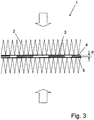
- eine vergrößerte, schematische Seitenansicht eines Ausschnitts einer erfindungsgemäßen Heizungsvorrichtung, und
- Fig. 4a-f
- verschiedene perspektivische Ansichten, teilweise in Verbindung mit Schnittdarstellungen, unterschiedlicher Anbringungsmöglichkeiten der isolierenden Elemente.
- Eine Heizungsvorrichtung 1 gemäß dem Ausführungsbeispiel dient als Zuheizer in einer Kraftfahrzeug-Klimaanlage, wobei sie in Luftströmungsrichtung gesehen nach einem herkömmlichen Heizer angeordnet ist. Die Heizungsvorrichtung 1 weist einen zweiteiligen Rahmen (nicht dargestellt) aus Kunststoff auf, vorliegend aus PA66, der spritzgegossen ist. In dem Rahmen ist eine Mehrzahl von der die wärmeübertragenden Fläche vergrößernden Wellrippen 2, plattenförmig ausgebildeten Keramik-PTC-Elementen 3, plattenförmig ausgebildete isolierende Elemente 4 und Kontaktblechen 5 angeordnet. Gemäß dem vorliegenden Ausführungsbeispiel ist die Abmessung der isolierenden Elemente 4 entsprechend der Abmessung der PTC-Elemente 3 gewählt, jedoch sind auch unterschiedliche Abmessungen möglich.
- Vorzugsweise entspricht die Breite maximal derjenigen der Kontaktbleche, insbesondere etwas geringer ist, so dass im zusammengebauten Zustand außenseitig ein kleiner Rand vorgesehen ist (siehe
Fig. 2 ). Die Länge der PTC-Elemente 3 und der isolierenden Elemente kann beliebig gewählt werden. Die Dicke d der Elemente 3 und 4 entspricht sich bevorzugt, wobei ggf. die isolierenden Elemente 4, um eine dickere Klebeschicht als bei den PTC-Elementen 3 vorsehen zu können, auch etwas dünner ausgebildet sein können. Die mittlere Dicke, d.h. die Dicke unter Berücksichtigung der unebenen Oberfläche, der isolierenden Elemente 4 ist bevorzugt etwas kleiner als die Dicke d der PTC-Elemente 3. - Vorliegend sind jeweils mehrere PTC-Elemente 3 und mindestens ein isolierendes Element 4 in einer Reihe und vorliegend jeweils etwas beabstandet voneinander zwischen zwei Kontaktblechen 5 angeordnet. Die elektrische Kontaktierung der PTC-Elemente erfolgt über die Kontaktbleche 5, von denen einzelne, vorliegend fünf, auf einer Seite, die über das Netz seitlich übersteht, mittels Klemmen 6 mit der Stromversorgung verbunden sind. Der Stromfluss durch das Netz erfolgt teilweise auch durch die Wellrippen 2, wie aus
Fig. 1 ersichtlich. - Die Kontaktbleche 5, die PTC-Elemente 3, die isolierenden Elemente 4 und die Wellrippen 2 sind miteinander verklebt. Um die Klebeverbindung zu verbessern, ist die Kontaktfläche der isolierenden Elemente 4 aufgerauht, so dass der Kleber besser haften kann und zumindest bereichsweise eine ausreichende, aber nicht zu große Filmdicke gewährleistet werden kann.
- Eine Unebenheit der Kontaktfläche der isolierenden Elemente kann auch durch das Vorsehen von regelmäßigen und/oder unregelmäßigen Riefen, Kanälen, Wellenstrukturen, Noppenstrukturen, Einprägungen, Löchern, Öffnungen o.ä. erzeugt werden.
- Um einen Kurzschluss zwischen den Kontaktblechen 5 im Bereich derer Enden zu verhindern, ist, wie in
Fig. 3 dargestellt, ein isolierendes Element 4 jeweils im Endbereich der Kontaktbleche 5 vorgesehen. Dieses kann auch kürzer als die PTC-Elemente 3 ausgebildet sein. Das Vorsehen eines derartigen Abstandselements direkt im Netz hat den Vorteil, dass Verformungen überstehender Enden der Kontaktbleche 5 vor dem Einbau in den Rahmen vermieden werden können. Ferner wird durch die bessere Fixierung der Kontaktbleche an den isolierenden Elementen 4 ein Aufbiegen der Kontaktbleche 5 und damit ein Lösen der Klebeverbindung und ein möglicher Kontaktverlust der PTC-Elemente zu den Kontaktblechen verhindert. In diesem äußersten Bereich, in welchem vorliegend die isolierenden Elemente 4 unter anderem angeordnet sind, in welchem üblicherweise kein PTC-Element angeordnet ist, und welcher nur bedingt der Wärmeübertragung dient, da er häufig vom Rahmen leicht verdeckt ist, nehmen daher derartige isolierende Elemente keinen Platz von PTC-Elementen ein. Zur zusätzlichen Stabilisierung und Fixierung können im Inneren des Netzes weitere isolierende Elemente 4 zwischen den Kontaktblechen 5 eingeklebt sein. - Die isolierenden Elemente können an einem Kontaktblech, insbesondere an zwei einander gegenüberliegenden, das Element zwischen sich aufnehmenden Kontaktblechen, mittels des zuvor beschriebenen Klebens angebracht sein, wie bspw. auch in
Fig. 4a angedeutet. Zusätzlich zum Vorsehen einer Klebeverbindung oder besonders bevorzugt bei entsprechender Ausgestaltung in Alleinstellung kann auch eine formschlüssige und/oder reibschlüssige Verbindung zwischen Kontaktblech und isolierendem Element vorgesehen sein, wie im Folgenden beispielhaft unter Bezugnahme auf dieFiguren 4b bis 4d beschrieben. Ist keine Klebeverbindung vorgesehen, so kann auf ein Aufrauhen der Oberfläche oder ähnliche Maßnahmen verzichtet werden. - Wie in
Fig. 4b dargestellt, kann das isolierende Element 4 mit zwei Vorsprüngen in Form von Zapfen 4a versehen sein, die nach oben und unten ragen und in Öffnungen, vorliegend Bohrungen, im Kontaktblech 5 aufgenommen sind. Ist das isolierende Element 4 aus einem (leicht) elastischen Material ausgebildet, so können die Zapfen in die Bohrungen eingepresst sein und die Kontaktbleche können auch ohne Klebstoff durch das isolierende Element 4 zusammengehalten werden. - Gemäß einer weiteren, in
Fig. 4c dargestellten Variante umgreift das isolierende Element 4 ein Kontaktblech 5 in einem Endbereich. Je nach Ausgestaltung kann das isolierende Element seitlich aufgeschoben oder mittels Aufbiegens der umgreifenden Arme 4b aufgesetzt werden. Im Falle dieser Lösung ist nur ein Kontaktblech mit dem isolierenden Element fest verbunden. Im Falle der Verwendung eines Klebers kann auch das andere Kontaktblech fest am isolierenden Element angebracht werden. Hierfür kann die Kontaktfläche des isolierenden Elements aufgerauht oder uneben ausgebildet sein. -
Fig. 4d zeigt eine Variante, gemäß der ein Endbereich eines Kontaktblechs von der Breitseite her verjüngt ausgebildet ist, so dass ein klammerartig mit zwei Armen 4c ausgebildetes isolierendes Element 4 auf den verjüngten Endbereich aufgesetzt werden kann. - Gemäß einer nicht in der Zeichnung dargestellten Variante ist das isolierende Element H-förmig ausgebildet, d.h. Arme stehen nach oben und unten ab. Diese Arme nehmen einen entsprechend der zuvor beschriebenen Variante verjüngten Bereich der Kontaktbleche zwischen sich auf. Die Arme können auch entsprechend den Armen 4c hintergreifend ausgebildet sein.
- Gemäß einer weiteren, nicht in der Zeichnung dargestellten Variante sind zwei Vorsprünge als Federarme mit hakenförmigen Enden ausgebildet, die in seitlich in dem Kontaktblech ausgebildete rechteckförmige Schlitze ragen und mit den Enden an der gegenüberliegenden Seite des Kontaktblechs anliegen. Für den Zusammenbau werden die Federarme kurzzeitig elastisch verformt. In der Endstellung nehmen sie wieder ihre Ausgangsstellung ein. Auch im Falle der Federarme ist eine H-förmige Ausgestaltung des isolierenden Elements möglich, d.h. das isolierende Element hält beide benachbarten Kontaktbleche fest.
- Obwohl vorstehend ausschließlich Keramik-PTC-Elemente beschrieben sind, können auch Kunststoff-PTC-Elemente als Heizelemente verwendet werden.
Claims (14)
- Elektrische Heizungsvorrichtung (1), insbesondere für ein Kraftfahrzeug, mit einem Wärmeübertragungsbereich zur Übertragung der erzeugten Wärme an ein durch die elektrische Heizungsvorrichtung hindurchströmendes Fluid, wobei im Wärmeübertragungsbereich eine Anzahl von zwischen Kontaktblechen (5) angeordneten, elektrischen Heizelementen vorgesehen ist, dadurch gekennzeichnet, dass zwischen zwei Kontaktblechen (5) neben mindestens einem elektrischen Heizelement weiterhin mindestens ein plattenförmig ausgebildetes isolierendes Element (4) angeordnet ist.
- Heizungsvorrichtung nach Anspruch 1, dadurch gekennzeichnet, dass das isolierende Element maximal die gleiche Abmessung wie das elektrische Heizelement in Richtung der Kontaktbleche hat.
- Heizungsvorrichtung nach Anspruch 1 oder 2, dadurch gekennzeichnet, dass das isolierende Element (4) zwischen den Kontaktblechen (5) eingeklebt ist.
- Heizungsvorrichtung nach einem der vorhergehenden Ansprüche, dadurch gekennzeichnet, dass das isolierende Element (4) form- und/oder kraftschlüssig mit mindestens einem der Kontaktbleche (5) verbunden ist.
- Heizungsvorrichtung nach Anspruch 4, dadurch gekennzeichnet, dass das isolierende Element (4) Arme (4b; 4c), welche seitlich an einem Kontaktblech (5) vorbeiragen, und/oder mindestens einen Vorsprung (4a) aufweist, der in eine Öffnung in einem Kontaktblech (5) eingeführt ist.
- Heizungsvorrichtung nach einem der vorhergehenden Ansprüche, dadurch gekennzeichnet, dass mindestens ein isolierendes Element (4) an einem Ende eines Kontaktblechs (5) angeordnet ist.
- Heizungsvorrichtung nach einem der vorhergehenden Ansprüche, dadurch gekennzeichnet, dass die Kontaktfläche, insbesondere die Klebefläche, des isolierenden Elements (4), mit der es an einem Kontaktblech (5) angeordnet ist, uneben ist.
- Heizungsvorrichtung nach Anspruch 7, dadurch gekennzeichnet, dass die unebene Fläche aufgerauht, mit regelmäßigen und/oder unregelmäßigen Riefen, Kanälen, Wellenstrukturen, Noppenstrukturen, Einprägungen, Löchern und/oder Öffnungen versehen ist.
- Heizungsvorrichtung nach einem der vorhergehenden Ansprüche, dadurch gekennzeichnet, dass das isolierende Element (4) spritzgegossen ist.
- Heizungsvorrichtung nach einem der vorhergehenden Ansprüche, dadurch gekennzeichnet, dass das isolierende Element (4) ein Kunststoff-Element ist.
- Heizungsvorrichtung nach einem der vorhergehenden Ansprüche, dadurch gekennzeichnet, dass das isolierende Element (4) aus einem weicheren Material gefertigt ist als das Kontaktblech (5)
- Heizungsvorrichtung nach einem der vorhergehenden Ansprüche, dadurch gekennzeichnet, dass das elektrische Heizelement ein PTC-Element (3), insbesondere ein Keramik-PTC-Element, ist.
- Heizungsvorrichtung nach einem der vorhergehenden Ansprüche, dadurch gekennzeichnet, dass die Heizungsvorrichtung (1) Wellrippen (2) aufweist, welche auf einer Seite der Kontaktbleche angebracht, insbesondere angeklebt, sind.
- Heizungsvorrichtung nach einem der vorhergehenden Ansprüche, dadurch gekennzeichnet, dass die elektrische Heizungsvorrichtung (1) ein isolierendes Gehäuse oder einen Rahmen aufweist.
Priority Applications (1)
| Application Number | Priority Date | Filing Date | Title |
|---|---|---|---|
| EP06291822.2A EP1926347B1 (de) | 2006-11-23 | 2006-11-23 | Elektrische Heizungsvorrichtung, insbesondere für ein Kraftfahrzeug |
Applications Claiming Priority (1)
| Application Number | Priority Date | Filing Date | Title |
|---|---|---|---|
| EP06291822.2A EP1926347B1 (de) | 2006-11-23 | 2006-11-23 | Elektrische Heizungsvorrichtung, insbesondere für ein Kraftfahrzeug |
Publications (2)
| Publication Number | Publication Date |
|---|---|
| EP1926347A1 EP1926347A1 (de) | 2008-05-28 |
| EP1926347B1 true EP1926347B1 (de) | 2017-07-05 |
Family
ID=37882350
Family Applications (1)
| Application Number | Title | Priority Date | Filing Date |
|---|---|---|---|
| EP06291822.2A Active EP1926347B1 (de) | 2006-11-23 | 2006-11-23 | Elektrische Heizungsvorrichtung, insbesondere für ein Kraftfahrzeug |
Country Status (1)
| Country | Link |
|---|---|
| EP (1) | EP1926347B1 (de) |
Families Citing this family (5)
| Publication number | Priority date | Publication date | Assignee | Title |
|---|---|---|---|---|
| EP2161515B1 (de) * | 2008-09-05 | 2016-11-09 | Mahle Behr France Rouffach S.A.S | Wärmeübertrager |
| EP2276321B1 (de) * | 2009-07-17 | 2017-04-05 | Mahle Behr France Rouffach S.A.S | Wärmeübertrager |
| FR2981437B1 (fr) * | 2011-10-14 | 2018-04-27 | Valeo Systemes Thermiques | Module de chauffe isole pour dispositif de chauffage additionnel |
| EP2865962B1 (de) | 2013-10-22 | 2019-01-09 | Mahle Behr France Rouffach S.A.S | Elektrische Heizvorrichtung |
| DE102022107554A1 (de) | 2022-03-30 | 2023-10-05 | Eberspächer Catem Gmbh & Co. Kg | PTC-Heizeinrichtung und elektrische Heizvorrichtung umfassend eine solche |
Family Cites Families (1)
| Publication number | Priority date | Publication date | Assignee | Title |
|---|---|---|---|---|
| KR100445722B1 (ko) * | 2003-11-18 | 2004-08-26 | 우리산업 주식회사 | 히트 로드 조립체 및 이를 포함하는 차량용 프리히터 |
-
2006
- 2006-11-23 EP EP06291822.2A patent/EP1926347B1/de active Active
Non-Patent Citations (1)
| Title |
|---|
| None * |
Also Published As
| Publication number | Publication date |
|---|---|
| EP1926347A1 (de) | 2008-05-28 |
Similar Documents
| Publication | Publication Date | Title |
|---|---|---|
| EP2505931B2 (de) | Elektrische Heizvorrichtung mit einem Leiterbahnen aufweisenenden Plattenelement und Verfahren zur Herstellung eines solchen Plattenelementes | |
| DE10037161C2 (de) | Temperaturschalter | |
| EP0705055B1 (de) | Elektrische Heizeinrichtung, insbesondere für ein Kraftfahrzeug | |
| EP2337425B1 (de) | Elektrische Heizvorrichtung und wärmeerzeugendes Element einer elektrischen Heizvorrichtung | |
| DE3042420C2 (de) | ||
| EP2608632B1 (de) | Elektrische Heizvorrichtung und Rahmen hierfür | |
| EP2298582B1 (de) | Elektrische Heizvorrichtung und Verfahren zu deren Herstellung | |
| EP1847786B1 (de) | Heizeinrichtung | |
| EP3493650A1 (de) | Elektrische heizvorrichtung | |
| DE3422362A1 (de) | Strahlungskuehler fuer halbleitervorrichtungen | |
| EP1768458A1 (de) | Wärmeerzeugendes Element einer Heizvorrichtung | |
| EP1509730A1 (de) | Waermetauscher, insbesondere fuer eine heizungs- oder klimaanlage eines kraftfahrzeugs | |
| DE102006055216B4 (de) | Heizeinrichtung für Dieselkraftstoff und beheizbares Dieselfiltersystem | |
| EP1926347B1 (de) | Elektrische Heizungsvorrichtung, insbesondere für ein Kraftfahrzeug | |
| WO2006012963A1 (de) | Heizungsanordnung mit einem heizelement, insbesondere für ein kraftfahrzeug | |
| EP3667197B1 (de) | Elektrische heizvorrichtung | |
| DE69902075T2 (de) | PTC Verdampfer für Insektizide und Duftstoffe | |
| EP1926346B1 (de) | Elektrische Heizungsvorrichtung, insbesondere für ein Kraftfahrzeug | |
| DE102006055872B3 (de) | Elektrische Heizung, insbesondere zur Verwendung als Zusatzheizung in Automobilen | |
| DE102020113402A1 (de) | Elektrische Heizvorrichtung | |
| EP0521181B1 (de) | PTC-Heizkörper | |
| EP4084577B1 (de) | Elektrische heizvorrichtung und verfahren zu deren herstellung | |
| DE102019211565A1 (de) | Elektrische Heizvorrichtung und Verfahren zu deren Herstellung | |
| EP1521499A1 (de) | Steckanordnung für eine Heizungsanordnung mit PTC-Elementen, insbesondere für ein Kraftfahrzeug | |
| EP1905130B1 (de) | Kontaktfeder in einem trägerrahmen eines antennenverstärkers eines fahrzeuges |
Legal Events
| Date | Code | Title | Description |
|---|---|---|---|
| PUAI | Public reference made under article 153(3) epc to a published international application that has entered the european phase |
Free format text: ORIGINAL CODE: 0009012 |
|
| AK | Designated contracting states |
Kind code of ref document: A1 Designated state(s): AT BE BG CH CY CZ DE DK EE ES FI FR GB GR HU IE IS IT LI LT LU LV MC NL PL PT RO SE SI SK TR |
|
| AX | Request for extension of the european patent |
Extension state: AL BA HR MK RS |
|
| 17P | Request for examination filed |
Effective date: 20081128 |
|
| AKX | Designation fees paid |
Designated state(s): DE FR GB |
|
| 17Q | First examination report despatched |
Effective date: 20090210 |
|
| RAP1 | Party data changed (applicant data changed or rights of an application transferred) |
Owner name: MAHLE BEHR FRANCE ROUFFACH S.A.S |
|
| GRAP | Despatch of communication of intention to grant a patent |
Free format text: ORIGINAL CODE: EPIDOSNIGR1 |
|
| INTG | Intention to grant announced |
Effective date: 20161215 |
|
| GRAS | Grant fee paid |
Free format text: ORIGINAL CODE: EPIDOSNIGR3 |
|
| GRAJ | Information related to disapproval of communication of intention to grant by the applicant or resumption of examination proceedings by the epo deleted |
Free format text: ORIGINAL CODE: EPIDOSDIGR1 |
|
| GRAL | Information related to payment of fee for publishing/printing deleted |
Free format text: ORIGINAL CODE: EPIDOSDIGR3 |
|
| RIN1 | Information on inventor provided before grant (corrected) |
Inventor name: DENNY, GEOFFREY Inventor name: WEINGAERTNER, STEPHANE Inventor name: MISS, PASCAL Inventor name: MOUGEY, MATHIEU Inventor name: ROBIN, NICOLAS Inventor name: BRUN, MICHEL Inventor name: GOGMOS, ERWAN Inventor name: ECKERLEN, GERARD Inventor name: SCHMITTHEISLER, CHRISTOPHE |
|
| INTC | Intention to grant announced (deleted) | ||
| GRAR | Information related to intention to grant a patent recorded |
Free format text: ORIGINAL CODE: EPIDOSNIGR71 |
|
| GRAA | (expected) grant |
Free format text: ORIGINAL CODE: 0009210 |
|
| AK | Designated contracting states |
Kind code of ref document: B1 Designated state(s): DE FR GB |
|
| INTG | Intention to grant announced |
Effective date: 20170530 |
|
| REG | Reference to a national code |
Ref country code: GB Ref legal event code: FG4D Free format text: NOT ENGLISH |
|
| REG | Reference to a national code |
Ref country code: DE Ref legal event code: R096 Ref document number: 502006015567 Country of ref document: DE |
|
| REG | Reference to a national code |
Ref country code: FR Ref legal event code: PLFP Year of fee payment: 12 |
|
| REG | Reference to a national code |
Ref country code: DE Ref legal event code: R097 Ref document number: 502006015567 Country of ref document: DE |
|
| PLBE | No opposition filed within time limit |
Free format text: ORIGINAL CODE: 0009261 |
|
| STAA | Information on the status of an ep patent application or granted ep patent |
Free format text: STATUS: NO OPPOSITION FILED WITHIN TIME LIMIT |
|
| 26N | No opposition filed |
Effective date: 20180406 |
|
| GBPC | Gb: european patent ceased through non-payment of renewal fee |
Effective date: 20171123 |
|
| PG25 | Lapsed in a contracting state [announced via postgrant information from national office to epo] |
Ref country code: GB Free format text: LAPSE BECAUSE OF NON-PAYMENT OF DUE FEES Effective date: 20171123 |
|
| PGFP | Annual fee paid to national office [announced via postgrant information from national office to epo] |
Ref country code: FR Payment date: 20201127 Year of fee payment: 15 |
|
| PG25 | Lapsed in a contracting state [announced via postgrant information from national office to epo] |
Ref country code: FR Free format text: LAPSE BECAUSE OF NON-PAYMENT OF DUE FEES Effective date: 20211130 |
|
| P01 | Opt-out of the competence of the unified patent court (upc) registered |
Free format text: CASE NUMBER: APP_36353/2024 Effective date: 20240618 |
|
| PGFP | Annual fee paid to national office [announced via postgrant information from national office to epo] |
Ref country code: DE Payment date: 20251119 Year of fee payment: 20 |