EP3667197B1 - Elektrische heizvorrichtung - Google Patents
Elektrische heizvorrichtung Download PDFInfo
- Publication number
- EP3667197B1 EP3667197B1 EP19212872.6A EP19212872A EP3667197B1 EP 3667197 B1 EP3667197 B1 EP 3667197B1 EP 19212872 A EP19212872 A EP 19212872A EP 3667197 B1 EP3667197 B1 EP 3667197B1
- Authority
- EP
- European Patent Office
- Prior art keywords
- heat
- heating device
- electric heating
- main side
- emitting
- Prior art date
- Legal status (The legal status is an assumption and is not a legal conclusion. Google has not performed a legal analysis and makes no representation as to the accuracy of the status listed.)
- Active
Links
Images


Classifications
-
- B—PERFORMING OPERATIONS; TRANSPORTING
- B60—VEHICLES IN GENERAL
- B60H—ARRANGEMENTS OF HEATING, COOLING, VENTILATING OR OTHER AIR-TREATING DEVICES SPECIALLY ADAPTED FOR PASSENGER OR GOODS SPACES OF VEHICLES
- B60H1/00—Heating, cooling or ventilating devices
- B60H1/22—Heating, cooling or ventilating devices the heat source being other than the propulsion plant
- B60H1/2215—Heating, cooling or ventilating devices the heat source being other than the propulsion plant the heat being derived from electric heaters
- B60H1/2225—Heating, cooling or ventilating devices the heat source being other than the propulsion plant the heat being derived from electric heaters arrangements of electric heaters for heating air
-
- F—MECHANICAL ENGINEERING; LIGHTING; HEATING; WEAPONS; BLASTING
- F24—HEATING; RANGES; VENTILATING
- F24H—FLUID HEATERS, e.g. WATER OR AIR HEATERS, HAVING HEAT-GENERATING MEANS, e.g. HEAT PUMPS, IN GENERAL
- F24H3/00—Air heaters
- F24H3/02—Air heaters with forced circulation
- F24H3/04—Air heaters with forced circulation the air being in direct contact with the heating medium, e.g. electric heating element
- F24H3/0405—Air heaters with forced circulation the air being in direct contact with the heating medium, e.g. electric heating element using electric energy supply, e.g. the heating medium being a resistive element; Heating by direct contact, i.e. with resistive elements, electrodes and fins being bonded together without additional element in-between
- F24H3/0429—For vehicles
- F24H3/0435—Structures comprising heat spreading elements in the form of fins
-
- H—ELECTRICITY
- H05—ELECTRIC TECHNIQUES NOT OTHERWISE PROVIDED FOR
- H05B—ELECTRIC HEATING; ELECTRIC LIGHT SOURCES NOT OTHERWISE PROVIDED FOR; CIRCUIT ARRANGEMENTS FOR ELECTRIC LIGHT SOURCES, IN GENERAL
- H05B3/00—Ohmic-resistance heating
- H05B3/0014—Devices wherein the heating current flows through particular resistances
-
- H—ELECTRICITY
- H05—ELECTRIC TECHNIQUES NOT OTHERWISE PROVIDED FOR
- H05B—ELECTRIC HEATING; ELECTRIC LIGHT SOURCES NOT OTHERWISE PROVIDED FOR; CIRCUIT ARRANGEMENTS FOR ELECTRIC LIGHT SOURCES, IN GENERAL
- H05B3/00—Ohmic-resistance heating
- H05B3/02—Details
- H05B3/06—Heater elements structurally combined with coupling elements or holders
-
- H—ELECTRICITY
- H05—ELECTRIC TECHNIQUES NOT OTHERWISE PROVIDED FOR
- H05B—ELECTRIC HEATING; ELECTRIC LIGHT SOURCES NOT OTHERWISE PROVIDED FOR; CIRCUIT ARRANGEMENTS FOR ELECTRIC LIGHT SOURCES, IN GENERAL
- H05B3/00—Ohmic-resistance heating
- H05B3/20—Heating elements having extended surface area substantially in a two-dimensional [2D] plane, e.g. plate-heater
- H05B3/34—Heating elements having extended surface area substantially in a two-dimensional [2D] plane, e.g. plate-heater flexible, e.g. heating nets or webs
- H05B3/36—Heating elements having extended surface area substantially in a two-dimensional [2D] plane, e.g. plate-heater flexible, e.g. heating nets or webs heating conductor embedded in insulating material
-
- B—PERFORMING OPERATIONS; TRANSPORTING
- B60—VEHICLES IN GENERAL
- B60H—ARRANGEMENTS OF HEATING, COOLING, VENTILATING OR OTHER AIR-TREATING DEVICES SPECIALLY ADAPTED FOR PASSENGER OR GOODS SPACES OF VEHICLES
- B60H1/00—Heating, cooling or ventilating devices
- B60H1/22—Heating, cooling or ventilating devices the heat source being other than the propulsion plant
- B60H2001/2228—Heating, cooling or ventilating devices the heat source being other than the propulsion plant controlling the operation of heaters
-
- F—MECHANICAL ENGINEERING; LIGHTING; HEATING; WEAPONS; BLASTING
- F24—HEATING; RANGES; VENTILATING
- F24H—FLUID HEATERS, e.g. WATER OR AIR HEATERS, HAVING HEAT-GENERATING MEANS, e.g. HEAT PUMPS, IN GENERAL
- F24H2250/00—Electrical heat generating means
- F24H2250/04—Positive temperature coefficients [PTC]; Negative temperature coefficients [NTC]
-
- F—MECHANICAL ENGINEERING; LIGHTING; HEATING; WEAPONS; BLASTING
- F28—HEAT EXCHANGE IN GENERAL
- F28F—DETAILS OF HEAT-EXCHANGE AND HEAT-TRANSFER APPARATUS, OF GENERAL APPLICATION
- F28F1/00—Tubular elements; Assemblies of tubular elements
- F28F1/10—Tubular elements and assemblies thereof with means for increasing heat-transfer area, e.g. with fins, with projections, with recesses
- F28F1/12—Tubular elements and assemblies thereof with means for increasing heat-transfer area, e.g. with fins, with projections, with recesses the means being only outside the tubular element
- F28F1/122—Tubular elements and assemblies thereof with means for increasing heat-transfer area, e.g. with fins, with projections, with recesses the means being only outside the tubular element and being formed of wires
-
- F—MECHANICAL ENGINEERING; LIGHTING; HEATING; WEAPONS; BLASTING
- F28—HEAT EXCHANGE IN GENERAL
- F28F—DETAILS OF HEAT-EXCHANGE AND HEAT-TRANSFER APPARATUS, OF GENERAL APPLICATION
- F28F13/00—Arrangements for modifying heat-transfer, e.g. increasing, decreasing
- F28F13/003—Arrangements for modifying heat-transfer, e.g. increasing, decreasing by using permeable mass, perforated or porous materials
-
- F—MECHANICAL ENGINEERING; LIGHTING; HEATING; WEAPONS; BLASTING
- F28—HEAT EXCHANGE IN GENERAL
- F28F—DETAILS OF HEAT-EXCHANGE AND HEAT-TRANSFER APPARATUS, OF GENERAL APPLICATION
- F28F2255/00—Heat exchanger elements made of materials having special features or resulting from particular manufacturing processes
- F28F2255/12—Heat exchanger elements made of materials having special features or resulting from particular manufacturing processes expanded or perforated metal plate
-
- F—MECHANICAL ENGINEERING; LIGHTING; HEATING; WEAPONS; BLASTING
- F28—HEAT EXCHANGE IN GENERAL
- F28F—DETAILS OF HEAT-EXCHANGE AND HEAT-TRANSFER APPARATUS, OF GENERAL APPLICATION
- F28F3/00—Plate-like or laminated elements; Assemblies of plate-like or laminated elements
- F28F3/02—Elements or assemblies thereof with means for increasing heat-transfer area, e.g. with fins, with recesses, with corrugations
- F28F3/022—Elements or assemblies thereof with means for increasing heat-transfer area, e.g. with fins, with recesses, with corrugations the means being wires or pins
-
- H—ELECTRICITY
- H05—ELECTRIC TECHNIQUES NOT OTHERWISE PROVIDED FOR
- H05B—ELECTRIC HEATING; ELECTRIC LIGHT SOURCES NOT OTHERWISE PROVIDED FOR; CIRCUIT ARRANGEMENTS FOR ELECTRIC LIGHT SOURCES, IN GENERAL
- H05B2203/00—Aspects relating to Ohmic resistive heating covered by group H05B3/00
- H05B2203/02—Heaters using heating elements having a positive temperature coefficient
Definitions
- Such an electric heating device is made, for example, of EP 2 607 121 A1
- the present applicant has previously known a PTC element.
- the PTC element is electrically connected via a contact plate, which in turn is connected to a contact pin to form a connection.
- Other generic electrical heating devices particularly for a motor vehicle, are known from EP 2 299 201 A1 or EP 2 242 327 A1 known.
- An electric heating device for a motor vehicle comprising conductor tracks designed as contact sheets, which clamp PTC elements between them on their inner surface and are contacted with corrugated fin elements on their outer surface.
- Each of the corrugated fin elements consists of a meandering, bent sheet metal strip.
- the sheet metal strips have perforations bent out of the plane by punching and bending the sheet metal, each of which forms air passages through the sheet metal material.
- a similar concept for increasing the heat transfer surface of a corrugated fin layer made of bent sheet material is known from US 2014/012 4494 A1 known.
- the present invention aims to provide an electric heating device which is able to dissipate the heat generated by the PTC elements in an improved manner while being as simple as possible in design.
- the heat-emitting elements extend as ribs between heat-generating layers of the layered structure, which are formed by the PTC element(s) arranged one behind the other in a plane and the conductor tracks provided for supplying current to the same.
- the heat-emitting elements consist of meandering, bent sheet metal strips, which are arranged directly or with an insulating layer (see Fig. EP 2 873 296 A2 ) against the heat-generating layer.
- the present invention proposes an electric heating device according to claim 1, in which the heat-emitting element is formed from a flat area of heat-conducting material provided with perforations in the form of a wire mesh or expanded metal.
- this flat structure has the same perforations over its entire flat extent.
- the flat structure in the form of the wire mesh can comprise heat-conducting fibers and is preferably formed as a woven fabric made of the heat-conducting fibers.
- the flat structure is preferably formed as a mesh made exclusively of wire.
- the wire is preferably a metallic wire.
- the wire mesh preferably has alternating intersecting "warp and weft threads" like a simple woven fabric.
- a punched sheet for example expanded metal or perforated sheet
- a perforated sheet it is preferable to bend the edges of the punched holes out of the plane of the perforated sheet in order to form projections protruding from the actual sheet plane, at which the medium to be heated is swirled as it passes over the heat-emitting element, thereby improving heat transfer between the heat-conducting element and the medium to be heated.
- a perforated sheet is a sheet provided with a regular grid of holes. The grid extends at least predominantly, if not completely, over the entire surface of the sheet.
- the perforated sheet is preferably a perforated plate in accordance with DIN 4185-2 or DIN 24021, whereby the plate is generally made of copper or aluminum. The same applies to the material of the expanded metal.
- the housing forming the inlet and outlet openings for the medium to be heated is preferably made of plastic. It encloses the layered structure and forms the inlet and outlet openings, which are preferably arranged in mutually parallel planes.
- the housing is preferably a frame-shaped housing, which leaves the entire layered structure free within the frame-shaped housing, so that the medium to be heated can pass over the layered structure.
- the housing preferably closely surrounds the layered structure, so that the medium to be heated and passing through the frame-shaped housing must necessarily pass over the layered structure and is thus inevitably heated.
- the orientation of the inlet and outlet openings relative to the layered structure is preferably such that the medium to be heated passes through the layered structure in a direction substantially perpendicular to the layers of the layered structure.
- This layered structure can comprise conductor elements, for example, in the form of contact plates that accommodate the at least one PTC element between them.
- Such conductor elements can form the aforementioned connections for electrically connecting the PTC elements to the power current, as well as conductor tracks that contact the PTC element.
- Such conductor elements can be formed from a stamped sheet metal. The conductor elements can each have contact tongues cut free by stamping to form the connections, or they can be formed as a single piece.
- the heat-dissipating elements can be placed directly against the PTC element or with the conductor element interposed. It is also possible to place the heat-dissipating element with an insulating layer interposed, thus indirectly against the conductor element.
- the heat-dissipating element can be formed exclusively from the wire mesh.
- a plate-shaped support is preferred, which is provided between the heat-emitting element and the PTC element and against which the heat-emitting element rests in a heat-conducting manner.
- Such a plate-shaped support essentially forms the base area of the heat-generating layer.
- This heat-generating layer can be formed exclusively by a PTC element and/or several PTC elements arranged one behind the other in the corresponding layer plane and the electrical conductor elements provided for them.
- the heat-generating layer can also comprise a positioning frame made of an electrically insulating material, which accommodates and positions the PTC element(s).
- the aforementioned plate-shaped support can be designed with the heat-emitting element as a pre-assembled unit, for example, welded, flanged, or glued, so that the plate-shaped support can be handled together with the heat-emitting element as an intermediate product during assembly of the electric heating device.
- the conductor element can also be provided between the plate-shaped support and the PTC element.
- the conductor element is located between the heat-emitting element and the PTC element in the heat dissipation direction.
- the PTC element bears directly or indirectly against the heat-emitting element with a heat-emitting main side surface.
- the conductor element usually does not cover the main side surface of the PTC element, or at most only slightly.
- the The heat-emitting element can also be placed against and connected to an electrically non-insulating sheet. This sheet forms the contact surface directly to the PTC element or the conductor element placed on the PTC element.
- the heat-emitting element also forms electrically conductive conductor tracks adjacent to the PTC element.
- specifically curved segments of the heat-emitting element are designed as heating fins that best transfer and dissipate heat from the PTC element to the medium to be heated, whereas other segments of the wire mesh are electrically conductively connected to the PTC element in order to supply current to it.
- each of the heat-emitting elements is formed from at least one track of wire mesh.
- the wire mesh is preferably bent so that various functional elements are formed from the flat structure through plastic deformation. Details of this are explained in the following specific description of the invention.
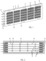
- the Fig. 1 shows a perspective side view of an embodiment of the electric heating device not according to the invention with a frame-shaped housing 2, consisting of a lower housing part 4 and an upper housing part 6. Both housing parts 4, 6 are positively connected to one another and accommodate a heating block 8 as a layered structure, which consists of several heat-generating elements 10 and heat-emitting elements 12 arranged in parallel layers to one another.
- the heat-emitting elements 12 consist of an initially flat and bent wire mesh 14, the exact design of which will be explained in more detail below in variants.
- the plastic housing 2 has two opposite frame openings, of which Fig. 1 Only the frame opening 16 formed by the upper housing part 6 is visible, forming the inlet or inlet openings for the medium to be heated.
- the medium to be heated is air.
- the exemplary embodiment is an air heater.
- the Fig. 2 shows details of the heating block 8 and its inclusion, particularly in the housing base 4, and shows the housing base 4 in a top view with the housing top removed.
- the heat-emitting elements 12 are only partially shown at the respective front ends of the housing base 4. Accordingly, the illustration in Fig. 2 also provides a view of a frame opening 18 formed by the lower housing part 4.
- a plurality of PTC elements 30 are received at predetermined locations in a positioning frame 28 made of an insulating material (in this case plastic) and positioned by this.
- a receptacle 32 is cut out in the positioning frame 28 for each individual PTC element 30, which receptacle encloses and thus fixes this PTC element 30.
- metal strips 34, 36 which form electrical conductor tracks for supplying current to the PTC heating elements 30 and through which the heat generated by the PTC heating elements is conducted to the heat-emitting elements 12 by means of heat transfer. These heat-emitting elements 12 lie directly against the metal strips 34, 36.
- the following description of various embodiments of the heat-emitting element 12 according to the present invention is based on a basic structure of the electric heating device as discussed above.
- the description refers to a sheet metal strip 34, against which the heat-emitting element 12 bears in the embodiment discussed here.
- an insulating layer (not shown here) can also be provided between the heat-emitting element and the contact sheet.
- the sheet metal strip or where this is missing, the PTC element, is shown in the longitudinal direction with straight edges.
- the longitudinal direction corresponds to a main direction of extension of each individual layer of the layered structure.
- the longitudinal direction extends transversely to the flow direction of the fluid to be heated. Its flow direction is indicated by arrow F.
- the flow direction F passes through the inlet and outlet openings 16, 18 and thus the housing 2 at right angles.
- the Fig. 4 shows a non-inventive embodiment of the heat-emitting element 13, as is generally known from the prior art.
- the heat-emitting element 12 has main side surfaces 40, which extend parallel to the fluid flow F to be heated and substantially transversely to the layers of the layer structure and accordingly act like heating fins 41.
- the main side surfaces 40 are connected to one another by webs 42, which also extend in the direction of extension of the fluid flow F, but are substantially parallel to the layers of the layer structure and accordingly parallel to the main side surfaces of the PTC element, which are designated by reference numeral 44 and extend parallel to the top and bottom sides of the respective sheet metal strip 34. Curved transitions are provided between the webs 42 and the main side surfaces 40.
- the webs 42 extend in two parallel planes, which are planes of the layer structure, wherein the lower plane E1 in this case coincides with the surface plane of the sheet metal strip 34 and the other plane E2 is provided at a distance therefrom that corresponds to the transverse extent of the heating fins 41.
- the webs 42 are arranged next to one another in a direction transverse to the passage direction F of the medium to be heated.
- the fluid to be heated can pass through the meandering, curved path of the wire mesh in a conventional manner, i.e., pass past the main side walls 40 for heat extraction. Due to the uneven surface of the wire mesh, however, the air flow is also swirled, which leads to improved heat transfer from the heat-emitting element 12 to the air to be heated.
- the main side surfaces 40 of the meandering curved path are arranged via webs 46 in two discrete planes E1, E2 lying parallel to a heat-emitting main side surface 44 of the PTC element.
- these webs 46 are arranged one behind the other in the direction of passage F of the medium to be heated.
- Such a configuration is in principle also possible with the specific shape of the meandering curved path according to Fig. 4 possible (see flow direction F2 there). Improved heat dissipation through turbulence is achieved in particular by the fact that the fluid flow F to be heated must pass through the main side surfaces 44 and is thus swirled when passing through the main side surfaces 40.
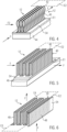
- the heat-emitting element is formed from a meandering curved path, so that several main side surfaces 48 are connected to one another via several webs 50. These webs 50 lie in two discrete planes E3, E4, which run parallel to the inlet and outlet openings 16, 18 of the housing 2. Accordingly, the fluid flow F of the medium to be heated passes through the webs 56 and passes essentially parallel to the main side surfaces 48.
- turbulence occurs on the surface and thus improved heat dissipation. This is particularly evident in the specific embodiment according to Fig. 6 , in which the fluid to be heated has to pass through several webs 50 when entering the heat-emitting element 12 and is thereby swirled.
- This turbulence also leads to a disturbance of those air layers that pass between the main side surfaces 48 without having to pass through a web 50.
- the Fig. 7 shows a further non-inventive embodiment of a heat-emitting element of the present invention, which is formed by bending a flat structure provided with perforations in the form of a wire mesh.
- this flat structure is not bent in a meandering manner in the present case. Rather, the structure has two main side surfaces 52 extending essentially at right angles to the direction of passage F of the fluid to be heated, and which are connected to one another via a single web 54 extending parallel to the layers of the layer structure.
- the web 54 is located on the side opposite the PTC element 30. This results in a Fig. 7 heat-dissipating fin designated by reference numeral 56. Opposite the web 54, the fin 56 can be open.
- the main side surfaces 52 extend parallel to the inlet and outlet openings 16, 18 of the housing 2.
- the web 54 extends parallel to the passage direction F.
- the rib 56 further has, on the side opposite the web 54, two fastening segments 58 extending parallel to the web 54, which are formed by bending the flat structure/wire mesh and can be glued to the sheet metal strip 34 to ensure good heat transfer, see enlarged detail in Fig. 8 .
- the Fig. 9 shows several fins 56 provided one behind the other in the direction of passage F of the fluid to be heated, each of which is designed like the Figs. 7 and 8 described rib 56 and are attached to the sheet metal strip 34.
- This embodiment is also not the subject of the invention.
- the ribs 56 can be handled together with the sheet metal strip as a preassembled unit.
- the ribs 56 can be soldered or glued to the sheet metal strip 34.
- a further sheet metal strip may also be provided, which serves only for contacting and/or pre-assembling the curved flat structure and can rest against the sheet metal strip 34 or 36 directly or with an insulating layer interposed.
- the Fig. 11 shows a modification of the embodiment according to Fig. 5 .
- several heating ribs can be used as in Fig. 5 be provided one behind the other in the direction of passage F of the fluid to be heated.
- Fastening segments 72 are formed by bending, transverse to the main direction of extension of the rib 70. These fastening segments 72 are directly connected to the main side surface 74 of the PTC element 30.
- the current is supplied directly through the heat-emitting element 12.
- the element can have a connection lug formed by punching the flat structure for introducing the power current.
- the connection lug can also be punched out of a sheet material and connected to the wire mesh by soldering.
- the previously discussed embodiments each provide improved heat dissipation because the air passing over the heat-emitting elements 12 is swirled on the non-smooth surface of the heat-emitting element 12, resulting in improved heat transfer.
- the Figure 12 shows an example of a flat structure 80 in the form of a wire mesh from which the previously discussed design of heat-emitting elements 12 can be bent.
Landscapes
- Engineering & Computer Science (AREA)
- Physics & Mathematics (AREA)
- Thermal Sciences (AREA)
- Mechanical Engineering (AREA)
- Chemical & Material Sciences (AREA)
- Combustion & Propulsion (AREA)
- General Engineering & Computer Science (AREA)
- Direct Air Heating By Heater Or Combustion Gas (AREA)
- Air-Conditioning For Vehicles (AREA)
- Resistance Heating (AREA)
Description
- Die vorliegende Erfindung betrifft eine elektrische Heizvorrichtung mit einer Ein- und Auslassöffnung für ein zu erwärmendes Fluid bildendes Gehäuse, das einen geschichteten Aufbau umschließt, der wenigstens ein PTC-Element, das elektrisch leitend mit Anschlüssen unterschiedlicher Polarität verbunden ist, und beidseitig mit dem PTC-Element wärmeleitend verbundene wärmeabgebende Elemente umfasst.
- Eine solche elektrische Heizvorrichtung ist beispielsweise aus
EP 2 607 121 A1 der vorliegenden Anmelderin vorbekannt. Bei dieser vorbekannten Lösung ist das PTC-Element über ein Kontaktblech elektrisch leitend kontaktiert, welches wiederum zur Ausbildung eines Anschlusses mit einem Kontaktstift verbunden ist. Weitere gattungsgemäße elektrische Heizvorrichtungen insbesondere für ein Kraftfahrzeug sind ausEP 2 299 201 A1 oderEP 2 242 327 A1 bekannt. - Aus
EP 0 243 077 A2 ist eine elektrische Heizvorrichtung für ein Kraftfahrzeug mit als Kontaktbleche ausgebildeten Leiterbahnen bekannt, die auf ihrer Innenfläche PTC-Elemente zwischen sich einklemmen und auf ihrer Außenfläche mit Wellrippenelementen kontaktiert sind. Jedes der Wellrippenelemente besteht jeweils aus einer mäandrierend gebogenen Blechbahn. Zur Erhöhung der Wärmeübertragung an die zu erwärmende Luft weisen die Blechbahnen durch Stanzen und Biegen des Blechs aus der Ebene herausgebogene Durchbrechungen auf, die jeweils Luftdurchtrittsöffnungen durch das Blechmaterial ausformen. Ein ähnliches Konzept zur Vergrößerung der Wärmeübertragungsfläche einer Wellrippenlage aus gebogenem Blechmaterial ist ausUS 2014/012 4494 A1 bekannt. - Die vorliegende Erfindung will eine elektrische Heizvorrichtung angeben, die in verbesserter Weise bei möglichst einfacher Gestaltung die von den PTC-Elementen erzeugte Wärme abzuleiten vermag.
- Bei diesen vorbekannten elektrischen Heizvorrichtungen erstrecken sich die wärmeabgebenden Elemente als Rippen zwischen wärmeerzeugenden Lagen des Schichtaufbaus, die durch das bzw. die in einer Ebene hintereinanderliegenden PTC-Elemente und die zur Bestromung derselben vorgesehenen Leiterbahnen gebildet sind. Dabei bestehen die wärmeabgebenden Elemente aus mäandrierend gebogenen Blechstreifen, die unmittelbar oder unter Zwischenlage einer isolierenden Schicht (vgl.
EP 2 873 296 A2 ) gegen die wärmeerzeugende Lage anliegen. - Für die Wirksamkeit der elektrischen Heizvorrichtung der vorerwähnten Art ist eine effektive Wärmeabfuhr bedeutsam. Der Fachmann ist daher bemüht, thermische Widerstände zwischen der wärmeerzeugenden Lage und den wärmeabgebenden Elementen, die üblicherweise beidseitig an der wärmerzeugenden Lage anliegen, gering zu halten.
- Im Hinblick darauf schlägt die vorliegende Erfindung eine elektrische Heizeinrichtung gemäß Anspruch 1 vor, bei der das wärmeabgebende Element aus einem mit Durchbrechungen versehenen flächigen Gebiete aus wärmeleitendem Material in Form eines Drahtgeflechts oder eines Streckmetalls ausgebildet ist. Dieses flächige Gebilde hat erfindungsgemäß über die gesamte flächige Erstreckung derselben Durchbrechungen. Das flächige Gebilde in Form des Drahtgeflechts kann wärmeleitende Fasern umfassen und bevorzugt als Gewebe aus den wärmeleitenden Fasern ausgebildet sein. Das flächige Gebilde ist bevorzugt als Geflecht ausschließlich aus Draht ausgebildet. Der Draht ist bevorzugt ein metallischer Draht. Das Drahtgeflecht hat bevorzugt wie ein einfaches Gewebe jeweils alternierend sich kreuzende "Kett- und Schussfäden".
- Als nicht erfindungsgemäßes flächiges Gebilde kann aber auch ein stanzbearbeitetes Blech, beispielsweise ein Streckmetall oder ein Lochblech verwendet werden. Sofern ein Lochblech verwendet wird ist es zu bevorzugen, die Ränder der ausgestanzten Löcher aus der Ebene des Lochblechs herauszubiegen, um aus der eigentlichen Blechebene herausragende Vorsprünge auszubilden, an denen das zu erwärmende Medium beim Überstreichen des wärmeabgebenden Elements verwirbelt wird, wodurch die Wärmeübertragung zwischen dem wärmeleitenden Element und dem zu erwärmenden Medium verbessert wird. Ein Lochblech ist dabei ein mit einem regelmäßigen Raster aus Löchern versehenes Blech. Das Raster erstreckt sich dabei zumindest überwiegend, wenn nicht gar vollständig über die gesamte Fläche des Blechs. Das Lochblech ist bevorzugt eine Lochplatte gemäß DIN 4185-2 bzw. DIN 24021, wobei die Platte in der Regel aus Kupfer oder Aluminium gebildet ist. Entsprechendes gilt für das Material des Streckmetalls.
- Das die Ein- und Auslassöffnungen für das zu erwärmende Medium bildende Gehäuse ist vorzugsweise aus Kunststoff ausgebildet. Es umschließt den geschichteten Aufbau und bildet die vorzugsweise in zueinander parallelen Ebenen angeordneten Ein- und Auslassöffnungen aus. Bevorzugt ist das Gehäuse ein rahmenförmiges Gehäuse, welches den gesamten Schichtaufbau innerhalb des rahmenförmigen Gehäuses freilässt, so dass das zu erwärmende Medium den Schichtaufbau überstreichen kann. Bei dieser bevorzugten Weiterbildung umgibt das Gehäuse bevorzugt den geschichteten Aufbau eng, so dass das zu erwärmende und das rahmenförmige Gehäuse durchsetzende Medium notwendig den geschichteten Aufbau überstreichen muss und somit zwangsläufig erwärmt wird.
- Die Ausrichtung der Ein- und Auslassöffnungen relativ zu dem geschichteten Aufbau ist dabei bevorzugt so, dass das zu erwärmende Medium den geschichteten Aufbau in einer Richtung im Wesentlichen rechtwinklig zu den Lagen des geschichteten Aufbaus durchsetzt.
- Dieser Schichtaufbau kann Leiterelemente beispielsweise in Form von Kontaktblechen umfassen, die zwischen sich das zumindest eine PTC-Element aufnehmen. Solche Leiterelemente können die zuvor erwähnten Anschlüsse zum elektrischen Anschluss der PTC-Elemente an den Leistungsstrom sowie das PTC-Element kontaktierende Leiterbahnen ausbilden. Solche Leiterelemente können aus einem stanzbearbeiteten Blech gebildet sein. Die Leiterelemente können zum Ausformen der Anschlüsse jeweils durch Stanzen freigeschnittene Kontaktzungen aufweisen oder diese einteilig ausbilden.
- Die wärmeabgebenden Elemente können unmittelbar oder unter Zwischenlage des Leiterelementes gegen das PTC-Element anliegen. Ebenso ist es möglich, das wärmeabgebende Element unter Zwischenlage einer Isolierlage und damit mittelbar gegen das Leiterelement anzulegen. Das wärmeabgebende Element kann ausschließlich aus dem Drahtgeflecht ausgeformt sein.
- Zu bevorzugen ist ein plattenförmiger Träger, der zwischen dem wärmeabgebenden Element und dem PTC-Element vorgesehen ist und gegen den das wärmeabgebende Element wärmeleitend an dem PTC-Element anliegt. Ein solcher plattenförmiger Träger hat im Grunde die Grundfläche der wärmeerzeugenden Lage. Diese wärmeerzeugende Lage kann ausschließlich durch ein PTC-Element und/oder mehrere in der entsprechenden Schichtebene hintereinanderliegende PTC-Elemente und den dazu vorgesehenen elektrischen Leiterelementen gebildet sein. Die wärmeerzeugende Lage kann auch einen Positionsrahmen aus einem elektrisch isolierenden Material umfassen, der das bzw. die PTC-Elemente in sich aufnimmt und lagepositioniert.
- Der zuvor erwähnte plattenförmige Träger kann mit dem wärmeabgebenden Element als vormontierte Einheit ausgebildet sein, beispielsweise verschweißt, umbördelt oder verklebt sein, so dass der plattenförmige Träger zusammen mit dem wärmeabgebenden Element als Zwischenerzeugnis bei der Montage der elektrischen Heizvorrichtung gehandhabt werden kann. Zwischen dem plattenförmigen Träger und dem PTC-Element kann noch das Leiterelement vorgesehen sein. So befindet sich das Leiterelement in Wärmeaustragrichtung zwischen dem wärmeabgebenden Element und dem PTC-Element. Das PTC-Element liegt bei dieser Fallgestaltung mit einer wärmeabgebenden Hauptseitenfläche mittelbar oder unmittelbar an dem wärmeabgebenden Element an. Bei einer unmittelbaren Anlage überdeckt das Leiterelement üblicherweise nicht oder allerhöchstens geringfügig die Hauptseitenfläche des PTC-Elements. Statt einer Isolierlage kann das wärmeabgebende Element auch gegen ein elektrisch nicht-isolierendes Blech angelegt und mit diesem verbunden sein. Dieses Blech bildet die Anlagefläche unmittelbar zu dem PTC-Element bzw. dem auf das PTC-Element aufgelegten Leiterelement.
- Gemäß einer bevorzugten Weiterbildung der vorliegenden Erfindung bildet das wärmeabgebende Element auch elektrisch leitend an dem PTC-Element anliegende Leiterbahnen aus. Bei dieser Fallgestaltung sind spezifisch gebogene Segmente des wärmeabgebenden Elementes als bestmöglich zur Übertragung der Wärme und Ableitung derselben von dem PTC-Element an das zu erwärmende Medium ausgeformte Heizrippen ausgebildet, wohingegen andere Segmente des Drahtgeflecht elektrisch leitend mit dem PTC-Element verbunden sind, um dieses zu bestromen. Gemäß einer bevorzugten Weiterbildung der vorliegenden Erfindung ist jedes der wärmeabgebenden Elemente aus zumindest einer Bahn Drahtgeflecht ausgeformt. Das Drahtgeflecht ist hierzu bevorzugt biegebearbeitet, so dass aus dem flächigen Gebilde durch plastische Verformung verschiedene funktionale Elemente ausgeformt werden. Details hierzu sind in der nachfolgenden speziellen Beschreibung der Erfindung verdeutlicht.
- Weitere Einzelheiten und Vorteile ergeben sich aus der nachfolgenden Beschreibung von Ausführungsbeispielen in Verbindung mit der Zeichnung. In dieser zeigen:
- Fig. 1
- eine perspektivische Seitenansicht eines Ausführungsbeispiels einer nichterfindungsgemäßen elektrischen Heizvorrichtung;
- Fig. 2
- eine Seitenansicht auf ein Gehäuseunterteil mit darin eingebautem Heizblock des in
Fig. 1 gezeigten nicht-erfindungsgemäßen Ausführungsbeispiels; - Fig. 3
- eine perspektivische Seitenansicht in Explosionsdarstellung der wesentlichen Bestandteile eines Ausführungsbeispiels eines wärmeerzeugenden Elementes;
- Fig. 4
- eine perspektivische Seitenansicht einer nicht-erfindungsgemäßen ersten Variante eines Ausführungsbeispiels eines wärmeabgebenden Elementes;
- Fig. 5
- eine perspektivische Seitenansicht einer nicht-erfindungsgemäßen zweiten Variante eines Ausführungsbeispiels eines wärmeabgebenden Elementes;
- Fig. 6
- eine perspektivische Seitenansicht einer erfindungsgemäßen dritten Variante eines Ausführungsbeispiels eines wärmeabgebenden Elementes;
- Fig. 7
- eine perspektivische Seitenansicht einer nicht-erfindungsgemäßen vierten Variante eines Ausführungsbeispiels eines wärmeabgebenden Elementes;
- Fig. 8
- eine vergrößerte perspektivische Seitenansicht des Details VIII in
Figur 7 ; - Fig. 9
- eine perspektivische Seitenansicht einer nicht-erfindungsgemäßen fünften Variante eines Ausführungsbeispiels eines wärmeabgebenden Elementes;
- Fig. 10
- eine perspektivische Seitenansicht einer nicht-erfindungsgemäßen sechsten Variante eines Ausführungsbeispiels eines wärmeabgebenden Elementes;
- Fig. 11
- eine perspektivische Seitenansicht einer nicht-erfindungsgemäßen siebten Variante eines Ausführungsbeispiels eines wärmeabgebenden Elementes und
- Fig. 12
- eine perspektivische Draufsicht eines Ausführungsbeispiels aus Drahtgeflecht.
- Die
Fig. 1 zeigt eine perspektivische Seitenansicht eines nicht-erfindungsgemäßen Ausführungsbeispiels der elektrischen Heizvorrichtung mit einem rahmenförmigen Gehäuse 2, bestehend aus einem Gehäuseunterteil 4 und einem Gehäuseoberteil 6. Beide Gehäuseteile 4, 6 sind formschlüssig miteinander verbunden und nehmen in sich einen Heizblock 8 als geschichteten Aufbau auf, der aus mehreren in parallelen Lagen zueinander angeordneten wärmeerzeugenden Elementen 10 und wärmeabgebenden Elementen 12 besteht. - Die wärmeabgebenden Elemente 12 bestehen aus einem zunächst flächigen und biegebearbeiteten Drahtgeflecht 14, dessen genaue Ausbildung in Varianten nahfolgend noch näher erläutert werden wird.
- Das aus Kunststoff gebildete Gehäuse 2 weist zwei gegenüberliegende Rahmenöffnungen auf, von denen in
Fig. 1 lediglich die durch das Gehäuseoberteil 6 gebildete Rahmenöffnung 16 zu sehen ist und die jeweils Ein- bzw. Einlassöffnungen für das zu erwärmende Medium ausbilden. Das zu erwärmende Medium ist vorliegend Luft. Das Ausführungsbeispiel ist ein Luftheizer. - Die
Fig. 2 zeigt Einzelheiten des Heizblocks 8 und dessen Aufnahme insbesondere in dem Gehäuseunterteil 4 und zeigt das Gehäuseunterteil 4 in einer Draufsicht bei weggenommenem Gehäuseoberteil. Die wärmeabgebenden Elemente 12 sind lediglich unvollständig an den jeweiligen stirnseitigen Enden des Gehäuseunterteils 4 dargestellt. Dementsprechend gibt die Darstellung inFig. 2 auch einen Blick auf eine von dem Gehäuseunterteil 4 gebildete Rahmenöffnung 18 frei. - Wie der
Fig. 3 zu entnehmen ist in einem Positionsrahmen 28 aus einem isolierenden Material (vorliegend Kunststoff) mehrere PTC-Elemente 30 an vorbestimmten Stellen aufgenommen und durch diesen positioniert. Vorliegend ist zu jedem einzelnen PTC-Element 30 eine Aufnahme 32 in dem Positionsrahmen 28 ausgespart, die dieses PTC-Element 30 umfänglich fasst und somit festlegt. Beidseitig an den jeweiligen PTC-Elementen 30, die nebeneinander in einer Ebene angeordnet sind, liegen Blechbänder 34, 36 an, welche elektrische Leiterbahnen zur Bestromung der PTC-Heizelemente 30 ausbilden und durch welche die von den PTC-Heizelementen erzeugte Wärme an die wärmeabgebenden Elemente 12 mittels Wärmeübertragung geleitet wird. Diese wärmeabgebenden Elemente 12 liegen unmittelbar an den Blechbändern 34, 36 an. - Weitere Details des Ausführungsbeispiels sind in
EP 2 025 541 A1 beschrieben. - Die nachfolgende Beschreibung von verschiedenen Ausgestaltungen des wärmeabgebenden Elementes 12 nach der vorliegenden Erfindung gehen von einem wie oben diskutierten grundlegenden Aufbau der elektrischen Heizvorrichtung aus. Die Beschreibung bezieht sich auf ein Blechband 34, gegen welches bei der hier diskutierten Ausführungsform an dem wärmeabgebenden Element 12 anliegt. Wie sich aus der allgemeinen Beschreibung ergibt, kann zwischen dem wärmeabgebenden Element und dem Kontaktblech auch eine hier nicht gezeigte Isolierlage vorgesehen sein.
- In den nachstehend diskutierten Figuren ist das Blechband bzw. sofem dieses fehlt, das PTC-Element in Längsrichtung mit geradlinig verlaufenden Rändern gezeigt. Die Längsrichtung entspricht einer Haupterstreckungsrichtung jeder einzelnen Lage des geschichteten Aufbaus. Die Längsrichtung erstreckt sich quer zu der Strömungsrichtung des zu erwärmenden Fluids. Dessen Strömungsrichtung ist mit dem Pfeil F angedeutet. Die Strömungsrichtung F durchsetzt die Ein- und Auslassöffnungen 16, 18 und damit das Gehäuse 2 rechtwinklig.
- Die
Fig. 4 zeigt eine nicht-erfindungsgemäße Ausgestaltung des wärmeabgebenden Elementes 13, wie es grundsätzlich aus dem Stand der Technik bekannt ist. Das wärmeabgebende Element 12 weist Hauptseitenflächen 40 auf, die sich parallel zu dem zu erwärmenden Fluidstrom F und im Wesentlichen quer zu den Lagen des Schichtaufbaus erstrecken und dementsprechend wie Heizrippen 41 wirken. Die Hauptseitenflächen 40 werden durch Stege 42 miteinander verbunden, die sich ebenfalls in Erstreckungsrichtung des Fluidstroms F erstrecken, allerdings im Wesentlichen parallel zu den Lagen des Schichtaufbaus und dementsprechend parallel zu Hauptseitenflächen des PTC-Elementes liegen, die mit Bezugszeichen 44 gekennzeichnet sind und sich parallel zu der Ober- bzw. Unterseite des jeweiligen Blechbandes 34 erstrecken. Zwischen den Stegen 42 und den Hauptseitenflächen 40 sind gekrümmte Übergänge vorgesehen. Die Stege 42 erstrecken sich dabei in zwei parallelen Ebenen, die Ebenen des Schichtaufbaus sind, wobei die untere Ebene E1 vorliegend mit der Oberflächenebene des Blechbandes 34 zusammenfällt und die andere Ebene E2 mit einem Abstand dazu vorgesehen ist, der der Quererstreckung der Heizrippen 41 entspricht. Dabei sind die Stege 42 in einer Richtung quer zu der Durchtrittsrichtung F des zu erwärmenden Mediums nebeneinander angeordnet. - Das zu erwärmende Fluid kann in an sich bekannter Weise die mäandrierend gebogene Bahn des Drahtgewebes durchsetzen, d.h. an den Hauptseitenwänden 40 zur Wärmeauskopplung vorbeistreichen. Aufgrund der ungleichmäßigen Oberfläche des Drahtgewebes ergibt sich indes auch eine Verwirbelung des Luftstromes, die zu einer verbesserten Wärmeübertragung von dem wärmeabgebenden Element 12 auf die zu erwärmende Luft führt.
- Auch bei dem in
Fig. 5 gezeigten nicht-erfindungsgemäßen Ausführungsbeispiel sind die Hauptseitenflächen 40 der mäandrierend gebogenen Bahn über Stege 46 in zwei sich parallel zu einer wärmeabgebenden Hauptseitenfläche 44 des PTC-Elementes liegenden diskreten Ebenen E1, E2 angeordnet. Allerdings sind diese Stege 46 in Durchtrittsrichtung F des zu erwärmenden Mediums hintereinander angeordnet. Eine solche Ausgestaltung ist prinzipiell auch mit der spezifischen Ausformung der mäandrierend gebogenen Bahn nachFig. 4 möglich (vgl. dort Strömungsrichtung F2). Ein verbesserter Wärmeaustrag durch Turbulenz wird insbesondere dadurch erreicht, dass der zu erwärmende Fluidstrom F jeweils die Hauptseitenflächen 44 durchsetzen muss und somit beim jeweiligen Durchsetzen der Hauptseitenflächen 40 verwirbelt wird. Dieser Effekt wird unabhängig davon erzielt, ob nun die gebogene Bahn streng rechteckig gebogen ist, wie diesFig. 5 verdeutlicht, bei der die Stege 46 rechtwinklig von den Hauptseitenflächen 40 abgehen, oder aber ein gerundeter Übergang zwischen den Hauptseitenflächen 40 und den Stegen 42 gewählt ist, wie er prinzipiell inFig. 4 verdeutlicht wird. - Auch bei dem in
Fig. 6 gezeigten erfindungsgemäßen Ausführungsbeispiel ist das wärmeabgebende Element aus einer mäandrierend gebogenen Bahn gebildet, so dass mehrere Hauptseitenflächen 48 über mehrere Stege 50 miteinander verbunden sind. Diese Stege 50 liegen indes in zwei diskreten Ebenen E3, E4, die parallel zu den Ein- und Auslassöffnungen 16, 18 des Gehäuses 2 verlaufen. Dementsprechend durchsetzt der Fluidstrom F des zu erwärmenden Mediums die Stege 56 und streicht im Wesentlichen parallel an den Hauptseitenflächen 48 vorbei. Auch hier ergibt sich aufgrund der nicht gleichmäßig glatten Oberfläche des wärmeabgebenden Elementes 12 eine Verwirbelung an der Oberfläche und somit eine verbesserte Wärmeabfuhr. Diese ergibt sich insbesondere bei der konkreten Ausgestaltung nachFig. 6 , bei welcher das zu erwärmende Fluid beim Eintritt in das wärmeabgebende Element 12 mehrere Stege 50 durchsetzen muss und hierbei verwirbelt wird. - Diese Verwirbelung führt auch zu einer Störung derjenigen Luftschichten, die zwischen die Hauptseitenflächen 48 gelangen ohne dabei einen Steg 50 durchsetzen zu müssen.
- Die
Fig. 7 zeigt ein weiteres nicht-erfindungsgemäßes Ausführungsbeispiel eines wärmeabgebenden Elementes der vorliegenden Erfindung, welches durch Biegen eines mit Durchbrechungen versehenen flächigen Gebildes in Form eines Drahtgeflechts ausgeformt ist. Dieses flächige Gebilde ist allerdings vorliegend nicht mäandrierend gebogen. Vielmehr hat das Gebilde zwei sich im Wesentlichen rechtwinklig zur Durchtrittsrichtung F des zu erwärmenden Fluids erstreckende Hauptseitenflächen 52, und die über einen einzigen Steg 54 miteinander verbunden sind, der sich parallel zu den Lagen des Schichtaufbaus erstreckt. Der Steg 54 befindet sich auf der dem PTC-Element 30 gegenüberliegenden Seite. Hierdurch ergibt sich eine inFig. 7 mit Bezugszeichen 56 gekennzeichnete wärmeabgebende Rippe. Gegenüberliegend zu dem Steg 54 kann die Rippe 56 offen sein. Die Hauptseitenflächen 52 erstrecken sich parallel zu den Ein- bzw. Auslassöffnungen 16, 18 des Gehäuses 2. Der Steg 54 hingegen erstreckt sich parallel zu der Durchtrittsrichtung F. Die Rippe 56 hat ferner an der dem Steg 54 gegenüberliegenden Seite zwei sich parallel zu dem Steg 54 erstreckende Befestigungssegmente 58, die durch Umbiegen des flächigen Gebildes/Drahtgeflechtes ausgebildet sind und mit dem Blechband 34 verklebt sein können, um eine gute Wärmeübertragung zu gewährleisten, vgl. vergrößertes Detail inFig. 8 . - Die
Fig. 9 zeigt mehrere in Durchtrittsrichtung F des zu erwärmenden Fluids hintereinander vorgesehene Rippen 56, die jeweils wie die zu denFig. 7 und 8 beschriebene Rippe 56 ausgebildet und an dem Blechband 34 befestigt sind. Dieses Ausführungsbeispiel ist ebenfalls nicht Gegenstand der Erfindung. Durch Befestigen an dem Blechband 34 können die Rippen 56 zusammen mit dem Blechband als vormontierte Einheit gehandhabt werden. Die Rippen 56 können mit dem Blechband 34 verlötet oder verklebt werden. - Die zuvor unter Bezugnahme auf die
Fig. 7 und 9 beschriebene Art der Befestigung zwischen dem wärmeabgebenden Element 12 und dem zugeordneten Blechband 34 gilt auch für die übrigen Ausführungsbeispiele. Es kann auch ein weiteres Blechband vorgesehen sein, das lediglich der Kontaktierung und/oder Vormontage des gebogenen flächigen Gebildes dient und gegen das Blechband 34 bzw. 36 direkt oder unter Zwischenlage einer Isolierlage anliegen kann. - Die
Fig. 10 zeigt ein nicht-erfindungsgemäßes alternatives Ausführungsbeispiel, bei welchem das wärmeabgebende Element mehrere Hohlzylinder 60 umfasst. Diese Hohlzylinder sind durch Biegen des flächigen Gebildes geformt und bilden einen Hohlraum 62 aus, der sich rechtwinklig zu den Lagen des Schichtaufbaus 34 und entlang einer Durchtrittsrichtung F erstreckt. Dementsprechend stehen die Hohlzylinder 60 auf dem zugeordneten Blechband auf. DieFig. 10 zeigt rechteckige Hohlzylinder 60. Es versteht sich, dass die verdeutlichte Grundform nur exemplarisch ist. Die Hohlzylinder 60 können jede beliebige Grundfläche aufweisen, also auch oval, rund oder polygonal gebogen sein. Quer zur Durchtrittsrichtung F des zu erwärmenden Fluids sind in einer Ebene des Schichtaufbaus mehrere Hohlzylinder 60 nebeneinander vorgesehen. - Die
Fig. 11 zeigt eine ebenfalls nicht-erfindungsgemäße Abwandlung zu dem Ausführungsbeispiel nachFig. 5 . Dabei verdeutlichtFig. 11 lediglich eine einzige Rippe 70 mit zwei Hauptseitenflächen 44, die über lediglich einen Steg 46 miteinander verbunden sind. Es können selbstverständlich mehrere Heizrippen wie inFig. 5 in Durchtrittsrichtung F des zu erwärmenden Fluids hintereinander vorgesehen sein. Sich quer zu der Haupterstreckungsrichtung der Rippe 70 sind durch Biegen Befestigungssegmente 72 ausgebildet. Diese Befestigungssegmente 72 sind unmittelbar mit der Hauptseitenfläche 74 des PTC-Elementes 30 verbunden. Bei diesem Ausführungsbeispiel erfolgt die Bestromung unmittelbar durch das wärmeabgebende Element 12. Dieses kann zu diesem Zweck eine durch Stanzen des flächigen Gebildes ausgeformte Anschlussfahne für die Einleitung des Leistungsstromes aufweisen. Bei einem Drahtgeflecht kann die Anschlussfahne auch aus einem Blechmaterial ausgestanzt und mit dem Drahtgeflecht durch Löten verbunden sein. - Die zuvor diskutierten Ausführungsbeispiele stellen jeweils einen verbesserten Wärmeaustrag bereit, da die die wärmeabgebenden Elemente 12 überstreichende Luft an der nicht glatten Oberfläche des wärmeabgebenden Elementes 12 verwirbelt wird, wodurch sich eine verbesserte Wärmeübertragung ergibt.
- Die
Figur 12 zeigt ein Beispiel eines flächigen Gebildes 80 in Form eines Drahtgeflechtes, aus dem die zuvor diskutierte Gestaltung von wärmeabgebenden Elementen 12 gebogen werden kann. -
- 2
- Gehäuse
- 4
- Gehäuseunterteil
- 6
- Gehäuseoberteil
- 8
- Heizblock
- 10
- wärmeerzeugende Element
- 12
- wärmeabgebendes Element
- 14
- Kontaktzunge
- 15
- Schlitz
- 16
- Rahmenöffnung/ Einlassöffnung
- 18
- Rahmenöffnung/Auslassöffnung
- 28
- Positionsrahmen
- 30
- PTC-Element
- 32
- Aufnahme für PTC-Heizelement
- 34
- Blechband
- 36
- Blechband
- 40
- Hauptseitenfläche des wärmeabgebenden Elements
- 41
- Heizrippen
- 42
- Steg
- 44
- Hauptseitenfläche des PTC-Elements
- 46
- Steg
- 48
- Hauptseitenfläche des wärmeabgebenden Elements
- 50
- Steg
- 52
- Hauptseitenfläche des wärmeabgebenden Elements
- 54
- Steg
- 56
- Rippe
- 58
- Befestigungssegment
- 60
- Hohlzylinder
- 62
- Hohlraum
- 70
- Rippe
- 72
- Befestigungssegment
- 74
- Hauptseitenfläche des PTC-Elements
- 80
- flächiges Gebilde / Drahtgeflecht
- E1
- erste Ebene
- E2
- zweite Ebene
- E3
- erste Ebene
- E4
- zweite Ebene
- F
- Durchtrittsrichtung des zu erwärmenden Fluids
Claims (12)
- Elektrische Heizvorrichtung, insbesondere für ein KFZ, mit einem Ein- und Auslassöffnungen (16; 18) für ein zu erwärmendes Medium bildenden Gehäuse (2), das einen geschichteten Aufbau (8) umschließt, der wenigstens ein PTC-Element (30), das elektrisch leitend mit Anschlüssen unterschiedlicher Polarität verbunden ist, und beidseitig mit dem PTC-Element (30) wärmeleitend verbundene wärmeabgebende Elemente (12) umfasst, dadurch gekennzeichnet, dass die wärmeabgebenden Elemente (12) ein mit Durchbrechungen versehenes flächiges Gebilde (80) in Form eines Drahtgeflechts oder eines Streckmetalls aus wärmeleitendem Material umfassen, dass das flächige Gebilde (80) über die gesamte flächige Erstreckung derselben Durchbrechungen hat, dass das wärmeabgebende Element (12) aus einer mäandrierend gebogenen Bahn gebildet ist und Hauptseitenflächen (48) aufweist, die durch Stege (46, 50) miteinander verbunden sind, dass die Stege (46, 50) in zwei diskreten Ebenen (E3, E4) liegen, die parallel zu dem Ein- und Auslassöffnungen (16, 18) des Gehäuses (2) verlaufen, und rechtwinklig von den Hauptseitenflächen (48) abgehen und dass das wärmeabgebende Element (12) mit einer der Hauptseitenflächen (48) unter Zwischenlage eines plattenförmigen Trägers (34) wärmeleitend an dem PTC-Element (30) anliegt.
- Elektrische Heizvorrichtung nach Anspruch 1, dadurch gekennzeichnet, dass das wärmeabgebende Element (12) aus dem mit Durchbrechungen versehenen flächigen Gebilde (80) gebildet ist.
- Elektrische Heizvorrichtung nach einem der vorherigen Ansprüche, dadurch gekennzeichnet, dass das mit Durchbrechungen versehene flächige Gebilde (80) das wärmeabgebende Element (12) und eine elektrisch leitend mit dem PTC-Element (30) verbundene Leiterbahn ausbildet.
- Elektrische Heizvorrichtung nach einem der vorherigen Ansprüche, dadurch gekennzeichnet, dass das Gehäuse (2) rahmenförmig ausgebildet ist und an gegenüberliegenden Seiten die Ein- und Auslassöffnungen (16; 18) ausbildet, zwischen denen der geschichtete Aufbau (8) freiliegt.
- Elektrische Heizvorrichtung nach einem der vorherigen Ansprüche, dadurch gekennzeichnet, dass jedes der wärmeabgebenden Elemente (12) aus zumindest einer Bahn des mit Durchbrechungen versehenen flächigen Gebilde (80) aus wärmeleitendem Material gebildet ist, die mäandrierend gebogen ist.
- Elektrische Heizvorrichtung nach Anspruch 5, dadurch gekennzeichnet, dass die Hauptseitenflächen (40) der mäandrierend gebogenen Bahn über Stege (42, 46) miteinander verbunden sind, die in zwei sich parallel zu einer wärmeabgebenden Hauptseitenfläche des PTC-Elementes liegenden Ebenen (E1; E2) angeordnet sind.
- Elektrische Heizvorrichtung nach Anspruch 6, dadurch gekennzeichnet, dass die Stege (42) in einer Richtung quer zu einer Durchtrittsrichtung (F) des zu erwärmenden Mediums nebeneinander angeordnet sind.
- Elektrische Heizvorrichtung nach Anspruch 6, dadurch gekennzeichnet, dass die Stege (46) in Durchtrittsrichtung (F) des zu erwärmenden Mediums hintereinander angeordnet sind.
- Elektrische Heizvorrichtung nach Anspruch 5, dadurch gekennzeichnet, dass die Hauptseitenflächen der mäandrierend gebogenen Bahn über Stege (50) miteinander verbunden sind, die in zwei, sich parallel zu der Ein- bzw. Auslassöffnung (16; 18) liegenden Ebenen (E3; E4) angeordnet sind.
- Elektrische Heizvorrichtung nach einem der Ansprüche 1 bis 4, dadurch gekennzeichnet, dass jedes der wärmeabgebenden Elemente (12) zumindest eine Bahn des mit Durchbrechungen versehenen flächigen Gebildes aus wärmeleitendem Material aufweist, die als wärmeabgebende Rippe (56) gebogen ist, die zumindest zwei sich im Wesentlichen parallel zu der Ein- bzw. Auslassöffnung erstreckende Hauptseitenfläche (52) und einen, die Hauptseitenflächen auf einer dem PTC-Element (30) gegenüberliegenden Seite verbindenden Steg (54) aufweisen.
- Elektrische Heizvorrichtung nach Anspruch 10, dadurch gekennzeichnet, dass in Durchtrittsrichtung (F) des zu erwärmenden Mediums mehrere Rippen (56) hintereinander angeordnet sind.
- Elektrische Heizvorrichtung nach einem der vorherigen Ansprüche, dadurch gekennzeichnet, dass das Leiterbahn durch zumindest ein zumindest teilflächig gegen das PTC-Element anliegendes umbogenes Segment des wärmeabgebenden Elements gebildet ist.
Applications Claiming Priority (1)
| Application Number | Priority Date | Filing Date | Title |
|---|---|---|---|
| DE102018220858.1A DE102018220858A1 (de) | 2018-12-03 | 2018-12-03 | Elektrische Heizvorrichtung |
Publications (2)
| Publication Number | Publication Date |
|---|---|
| EP3667197A1 EP3667197A1 (de) | 2020-06-17 |
| EP3667197B1 true EP3667197B1 (de) | 2025-03-26 |
Family
ID=68762605
Family Applications (1)
| Application Number | Title | Priority Date | Filing Date |
|---|---|---|---|
| EP19212872.6A Active EP3667197B1 (de) | 2018-12-03 | 2019-12-02 | Elektrische heizvorrichtung |
Country Status (4)
| Country | Link |
|---|---|
| US (1) | US11912106B2 (de) |
| EP (1) | EP3667197B1 (de) |
| CN (1) | CN111263475A (de) |
| DE (1) | DE102018220858A1 (de) |
Families Citing this family (2)
| Publication number | Priority date | Publication date | Assignee | Title |
|---|---|---|---|---|
| DE102016225462A1 (de) * | 2016-12-19 | 2018-06-21 | E.G.O. Elektro-Gerätebau GmbH | Heizeinrichtung, Kochgerät mit einer Heizeinrichtung und Verfahren zur Herstellung eines Heizelements |
| DE102021109618A1 (de) * | 2021-04-16 | 2022-10-20 | Eberspächer Catem Gmbh & Co. Kg | PTC-Heizeinrichtung |
Citations (3)
| Publication number | Priority date | Publication date | Assignee | Title |
|---|---|---|---|---|
| JPH07324884A (ja) * | 1994-05-31 | 1995-12-12 | Showa Alum Corp | 熱交換器用コルゲート・フィン |
| EP1715276A2 (de) * | 2005-04-18 | 2006-10-25 | Behr GmbH & Co. KG | Wärmetauscher |
| DE102014208955A1 (de) * | 2014-05-12 | 2015-11-12 | Fraunhofer-Gesellschaft zur Förderung der angewandten Forschung e.V. | Wärmeübertragungsvorrichtung und deren Verwendung |
Family Cites Families (33)
| Publication number | Priority date | Publication date | Assignee | Title |
|---|---|---|---|---|
| US4743321A (en) * | 1985-10-04 | 1988-05-10 | Raychem Corporation | Devices comprising PTC conductive polymers |
| EP0243077A3 (de) * | 1986-04-17 | 1988-03-23 | Ford Motor Company Limited | Elektrisches Heizelement für Kraftfahrzeuge |
| DE50207329D1 (de) * | 2002-12-19 | 2006-08-03 | Catem Gmbh & Co Kg | Elektrische Heizvorrichtung mit Gehäuse |
| DE50305966D1 (de) * | 2003-09-11 | 2007-01-25 | Catem Gmbh & Co Kg | Elektrische Heizvorrichtung mit versiegeltem Heizelement |
| DE102006018784B4 (de) * | 2005-12-20 | 2007-12-20 | Beru Ag | Elektrische Heizvorrichtung, insbesondere für Automobile |
| JP2008041298A (ja) * | 2006-08-02 | 2008-02-21 | Matsushita Electric Ind Co Ltd | 柔軟性ptc発熱体 |
| WO2008122362A1 (de) * | 2007-04-04 | 2008-10-16 | Beru Aktiengesellschaft | Elektrische heizvorrichtung, insbesondere für automobile |
| EP2025541B1 (de) | 2007-07-18 | 2013-01-02 | Eberspächer catem GmbH & Co. KG | Wärmeerzeugendes Element einer elektrischen Heizvorrichtung |
| ES2382138T3 (es) * | 2007-07-18 | 2012-06-05 | Eberspächer Catem Gmbh & Co. Kg | Dispositivo de calefacción eléctrico |
| DE202009005582U1 (de) | 2009-04-14 | 2010-09-02 | Eberspächer Catem Gmbh & Co. Kg | Elektrische Heizvorrichtung |
| EP2299200B1 (de) * | 2009-09-22 | 2013-02-06 | Eberspächer catem GmbH & Co. KG | Elektrische Heizvorrichtung |
| EP2299201B1 (de) | 2009-09-22 | 2012-08-29 | Eberspächer catem GmbH & Co. KG | Elektrische Heizvorrichtung |
| EP2466222B1 (de) * | 2010-12-20 | 2013-06-05 | Eberspächer catem GmbH & Co. KG | Elektrische Heizvorrichtung |
| DE102011017376A1 (de) * | 2011-04-16 | 2012-10-18 | Borgwarner Beru Systems Gmbh | Elektrische Heizeinrichtung |
| EP2607121B2 (de) | 2011-12-22 | 2020-07-08 | Eberspächer catem GmbH & Co. KG | Elektrische Heizvorrichtung, insbesondere für ein Kraftfahrzeug |
| CN104203612B (zh) * | 2012-02-28 | 2016-08-24 | 汉拿伟世通空调有限公司 | 车辆用加热器 |
| WO2013172603A1 (ko) * | 2012-05-16 | 2013-11-21 | 한라비스테온공조 주식회사 | 차량용 히터 |
| DE112013003447T5 (de) * | 2012-07-09 | 2015-04-16 | Halla Visteon Climate Control Corp. | Heizvorrichtung für Fahrzeuge |
| DE102012013770A1 (de) | 2012-07-11 | 2014-01-16 | Eberspächer Catem Gmbh & Co. Kg | Wärme erzeugendes Element |
| US20140124494A1 (en) * | 2012-11-05 | 2014-05-08 | Betacera Inc. | Car interior compartment heater |
| DE102012112837B4 (de) * | 2012-12-21 | 2015-05-13 | Borgwarner Ludwigsburg Gmbh | Fahrzeugheizung und Verfahren zum Herstellen einer Fahrzeugheizung |
| CN104955666B (zh) * | 2013-01-29 | 2017-09-19 | 翰昂汽车零部件有限公司 | 用于机动车辆的加热器 |
| CN203327269U (zh) * | 2013-04-28 | 2013-12-04 | 比亚迪股份有限公司 | 一种电加热器、除霜器、空调供暖系统及汽车 |
| EP3101999B1 (de) * | 2015-06-02 | 2021-03-17 | Eberspächer catem GmbH & Co. KG | Ptc-heizelement und elektrische heizvorrichtung für ein kraftfahrzeug umfassend ein solches ptc-heizelement |
| KR101913121B1 (ko) * | 2016-01-28 | 2018-10-31 | 자화전자(주) | 독립제어 피티씨히터 및 장치 |
| CN108883687B (zh) * | 2016-03-30 | 2021-07-27 | 阿莫善斯有限公司 | 用于车辆加热器的正温度系数单元、包括其的正温度系数加热器及车辆空调装置 |
| KR101913830B1 (ko) * | 2016-12-05 | 2018-10-31 | 주식회사 코쿤디자인 | 기능성 led 어셈블리를 이용한 디스플레이 장치 |
| WO2018117484A1 (ko) * | 2016-12-20 | 2018-06-28 | 엘지이노텍 주식회사 | 히팅 로드, 이를 포함하는 발열 모듈 및 이를 포함하는 히팅 장치 |
| KR102186982B1 (ko) * | 2017-08-31 | 2020-12-04 | 한온시스템 주식회사 | 피티씨 히터 |
| FR3075553B1 (fr) * | 2017-12-19 | 2022-05-20 | Valeo Systemes Thermiques | Dispositif de chauffage electrique avec moyens de mise a la masse |
| FR3075552B1 (fr) * | 2017-12-19 | 2022-05-20 | Valeo Systemes Thermiques | Dispositif de chauffage electrique avec moyens de mise a la masse |
| DE102017223782A1 (de) * | 2017-12-22 | 2019-06-27 | Eberspächer Catem Gmbh & Co. Kg | Wärmeerzeugendes Element einer elektrischen Heizvorrichtung |
| DE102019208967B4 (de) * | 2019-06-19 | 2025-03-06 | Eberspächer Catem Gmbh & Co. Kg | Verfahren zur Herstellung eines wärmeerzeugenden Elementes |
-
2018
- 2018-12-03 DE DE102018220858.1A patent/DE102018220858A1/de active Pending
-
2019
- 2019-12-02 EP EP19212872.6A patent/EP3667197B1/de active Active
- 2019-12-03 CN CN201911226117.0A patent/CN111263475A/zh active Pending
- 2019-12-03 US US16/701,861 patent/US11912106B2/en active Active
Patent Citations (3)
| Publication number | Priority date | Publication date | Assignee | Title |
|---|---|---|---|---|
| JPH07324884A (ja) * | 1994-05-31 | 1995-12-12 | Showa Alum Corp | 熱交換器用コルゲート・フィン |
| EP1715276A2 (de) * | 2005-04-18 | 2006-10-25 | Behr GmbH & Co. KG | Wärmetauscher |
| DE102014208955A1 (de) * | 2014-05-12 | 2015-11-12 | Fraunhofer-Gesellschaft zur Förderung der angewandten Forschung e.V. | Wärmeübertragungsvorrichtung und deren Verwendung |
Also Published As
| Publication number | Publication date |
|---|---|
| EP3667197A1 (de) | 2020-06-17 |
| US20200171920A1 (en) | 2020-06-04 |
| DE102018220858A1 (de) | 2020-06-04 |
| CN111263475A (zh) | 2020-06-09 |
| US11912106B2 (en) | 2024-02-27 |
Similar Documents
| Publication | Publication Date | Title |
|---|---|---|
| EP0379873B1 (de) | Vorrichtung zum Erhitzen von Gasen | |
| EP1061776B1 (de) | Heizvorrichtung zur Lufterwärmung | |
| EP2025541B1 (de) | Wärmeerzeugendes Element einer elektrischen Heizvorrichtung | |
| EP2330865B1 (de) | Elektrische Heizvorrichtung | |
| DE202010006739U1 (de) | Durchlauferhitzer | |
| EP0333906B1 (de) | Kaltleiter-PTC-Heizkörper | |
| EP3667197B1 (de) | Elektrische heizvorrichtung | |
| DE102006055216B4 (de) | Heizeinrichtung für Dieselkraftstoff und beheizbares Dieselfiltersystem | |
| WO2006012963A1 (de) | Heizungsanordnung mit einem heizelement, insbesondere für ein kraftfahrzeug | |
| DE102010033309A1 (de) | Wärmetauscher-Lamellenmodul, Wärmetauscher und elektrisches Heizmodul | |
| EP1731340B1 (de) | Elektrische Heizeinrichtung | |
| DE102019202543B4 (de) | PTC-Heizelement und elektrische Heizvorrichtung mit einem solchen PTC-Heizelement | |
| EP0225533B1 (de) | Flächenwärmetauscher | |
| DE102010008354A1 (de) | Elektrische Anschlussklemme | |
| EP1522439A1 (de) | Heizungsanordnung mit PTC-Element, insbesondere für ein Kraftfahrzeug | |
| DE102017130508A1 (de) | Flexibler flächiger Heizer und Verfahren zu dessen Herstellung | |
| EP1926347B1 (de) | Elektrische Heizungsvorrichtung, insbesondere für ein Kraftfahrzeug | |
| DE2533936A1 (de) | Elektrischer heizkoerper fuer hausgeraete o.dgl. | |
| AT526741A2 (de) | Wärmestrahler | |
| DE102011017109B4 (de) | Heizeinrichtung | |
| EP3511645B1 (de) | Elektrische heizvorrichtung | |
| EP0705925A2 (de) | Heizeinrichtung mit auswechselbaren Fadenführern | |
| DE102014202293A1 (de) | Kühlkörper | |
| DE20217309U1 (de) | Heizkörper für gasförmige Medien | |
| EP1698840A2 (de) | Ptc-Heizer, insbesondere für ein Kraftfahrzeug |
Legal Events
| Date | Code | Title | Description |
|---|---|---|---|
| PUAI | Public reference made under article 153(3) epc to a published international application that has entered the european phase |
Free format text: ORIGINAL CODE: 0009012 |
|
| STAA | Information on the status of an ep patent application or granted ep patent |
Free format text: STATUS: THE APPLICATION HAS BEEN PUBLISHED |
|
| AK | Designated contracting states |
Kind code of ref document: A1 Designated state(s): AL AT BE BG CH CY CZ DE DK EE ES FI FR GB GR HR HU IE IS IT LI LT LU LV MC MK MT NL NO PL PT RO RS SE SI SK SM TR |
|
| AX | Request for extension of the european patent |
Extension state: BA ME |
|
| STAA | Information on the status of an ep patent application or granted ep patent |
Free format text: STATUS: REQUEST FOR EXAMINATION WAS MADE |
|
| 17P | Request for examination filed |
Effective date: 20201215 |
|
| RBV | Designated contracting states (corrected) |
Designated state(s): AL AT BE BG CH CY CZ DE DK EE ES FI FR GB GR HR HU IE IS IT LI LT LU LV MC MK MT NL NO PL PT RO RS SE SI SK SM TR |
|
| STAA | Information on the status of an ep patent application or granted ep patent |
Free format text: STATUS: EXAMINATION IS IN PROGRESS |
|
| 17Q | First examination report despatched |
Effective date: 20221118 |
|
| GRAP | Despatch of communication of intention to grant a patent |
Free format text: ORIGINAL CODE: EPIDOSNIGR1 |
|
| STAA | Information on the status of an ep patent application or granted ep patent |
Free format text: STATUS: GRANT OF PATENT IS INTENDED |
|
| INTG | Intention to grant announced |
Effective date: 20241018 |
|
| GRAS | Grant fee paid |
Free format text: ORIGINAL CODE: EPIDOSNIGR3 |
|
| GRAA | (expected) grant |
Free format text: ORIGINAL CODE: 0009210 |
|
| STAA | Information on the status of an ep patent application or granted ep patent |
Free format text: STATUS: THE PATENT HAS BEEN GRANTED |
|
| AK | Designated contracting states |
Kind code of ref document: B1 Designated state(s): AL AT BE BG CH CY CZ DE DK EE ES FI FR GB GR HR HU IE IS IT LI LT LU LV MC MK MT NL NO PL PT RO RS SE SI SK SM TR |
|
| P01 | Opt-out of the competence of the unified patent court (upc) registered |
Free format text: CASE NUMBER: APP_7360/2025 Effective date: 20250212 |
|
| REG | Reference to a national code |
Ref country code: GB Ref legal event code: FG4D Free format text: NOT ENGLISH |
|
| REG | Reference to a national code |
Ref country code: CH Ref legal event code: EP |
|
| REG | Reference to a national code |
Ref country code: DE Ref legal event code: R096 Ref document number: 502019013106 Country of ref document: DE |
|
| REG | Reference to a national code |
Ref country code: IE Ref legal event code: FG4D Free format text: LANGUAGE OF EP DOCUMENT: GERMAN |
|
| PG25 | Lapsed in a contracting state [announced via postgrant information from national office to epo] |
Ref country code: RS Free format text: LAPSE BECAUSE OF FAILURE TO SUBMIT A TRANSLATION OF THE DESCRIPTION OR TO PAY THE FEE WITHIN THE PRESCRIBED TIME-LIMIT Effective date: 20250626 |
|
| PG25 | Lapsed in a contracting state [announced via postgrant information from national office to epo] |
Ref country code: FI Free format text: LAPSE BECAUSE OF FAILURE TO SUBMIT A TRANSLATION OF THE DESCRIPTION OR TO PAY THE FEE WITHIN THE PRESCRIBED TIME-LIMIT Effective date: 20250326 |
|
| REG | Reference to a national code |
Ref country code: LT Ref legal event code: MG9D |
|
| PG25 | Lapsed in a contracting state [announced via postgrant information from national office to epo] |
Ref country code: NO Free format text: LAPSE BECAUSE OF FAILURE TO SUBMIT A TRANSLATION OF THE DESCRIPTION OR TO PAY THE FEE WITHIN THE PRESCRIBED TIME-LIMIT Effective date: 20250626 |
|
| PG25 | Lapsed in a contracting state [announced via postgrant information from national office to epo] |
Ref country code: HR Free format text: LAPSE BECAUSE OF FAILURE TO SUBMIT A TRANSLATION OF THE DESCRIPTION OR TO PAY THE FEE WITHIN THE PRESCRIBED TIME-LIMIT Effective date: 20250326 |
|
| PG25 | Lapsed in a contracting state [announced via postgrant information from national office to epo] |
Ref country code: LV Free format text: LAPSE BECAUSE OF FAILURE TO SUBMIT A TRANSLATION OF THE DESCRIPTION OR TO PAY THE FEE WITHIN THE PRESCRIBED TIME-LIMIT Effective date: 20250326 |
|
| PG25 | Lapsed in a contracting state [announced via postgrant information from national office to epo] |
Ref country code: GR Free format text: LAPSE BECAUSE OF FAILURE TO SUBMIT A TRANSLATION OF THE DESCRIPTION OR TO PAY THE FEE WITHIN THE PRESCRIBED TIME-LIMIT Effective date: 20250627 Ref country code: BG Free format text: LAPSE BECAUSE OF FAILURE TO SUBMIT A TRANSLATION OF THE DESCRIPTION OR TO PAY THE FEE WITHIN THE PRESCRIBED TIME-LIMIT Effective date: 20250326 |
|
| REG | Reference to a national code |
Ref country code: NL Ref legal event code: MP Effective date: 20250326 |
|
| PG25 | Lapsed in a contracting state [announced via postgrant information from national office to epo] |
Ref country code: NL Free format text: LAPSE BECAUSE OF FAILURE TO SUBMIT A TRANSLATION OF THE DESCRIPTION OR TO PAY THE FEE WITHIN THE PRESCRIBED TIME-LIMIT Effective date: 20250326 |
|
| PG25 | Lapsed in a contracting state [announced via postgrant information from national office to epo] |
Ref country code: SE Free format text: LAPSE BECAUSE OF FAILURE TO SUBMIT A TRANSLATION OF THE DESCRIPTION OR TO PAY THE FEE WITHIN THE PRESCRIBED TIME-LIMIT Effective date: 20250326 |
|
| PG25 | Lapsed in a contracting state [announced via postgrant information from national office to epo] |
Ref country code: SM Free format text: LAPSE BECAUSE OF FAILURE TO SUBMIT A TRANSLATION OF THE DESCRIPTION OR TO PAY THE FEE WITHIN THE PRESCRIBED TIME-LIMIT Effective date: 20250326 |
|
| PG25 | Lapsed in a contracting state [announced via postgrant information from national office to epo] |
Ref country code: PT Free format text: LAPSE BECAUSE OF FAILURE TO SUBMIT A TRANSLATION OF THE DESCRIPTION OR TO PAY THE FEE WITHIN THE PRESCRIBED TIME-LIMIT Effective date: 20250728 Ref country code: ES Free format text: LAPSE BECAUSE OF FAILURE TO SUBMIT A TRANSLATION OF THE DESCRIPTION OR TO PAY THE FEE WITHIN THE PRESCRIBED TIME-LIMIT Effective date: 20250326 |
|
| PG25 | Lapsed in a contracting state [announced via postgrant information from national office to epo] |
Ref country code: PL Free format text: LAPSE BECAUSE OF FAILURE TO SUBMIT A TRANSLATION OF THE DESCRIPTION OR TO PAY THE FEE WITHIN THE PRESCRIBED TIME-LIMIT Effective date: 20250326 Ref country code: IT Free format text: LAPSE BECAUSE OF FAILURE TO SUBMIT A TRANSLATION OF THE DESCRIPTION OR TO PAY THE FEE WITHIN THE PRESCRIBED TIME-LIMIT Effective date: 20250326 |
|
| PG25 | Lapsed in a contracting state [announced via postgrant information from national office to epo] |
Ref country code: EE Free format text: LAPSE BECAUSE OF FAILURE TO SUBMIT A TRANSLATION OF THE DESCRIPTION OR TO PAY THE FEE WITHIN THE PRESCRIBED TIME-LIMIT Effective date: 20250326 |
|
| PG25 | Lapsed in a contracting state [announced via postgrant information from national office to epo] |
Ref country code: RO Free format text: LAPSE BECAUSE OF FAILURE TO SUBMIT A TRANSLATION OF THE DESCRIPTION OR TO PAY THE FEE WITHIN THE PRESCRIBED TIME-LIMIT Effective date: 20250326 |
|
| PG25 | Lapsed in a contracting state [announced via postgrant information from national office to epo] |
Ref country code: SK Free format text: LAPSE BECAUSE OF FAILURE TO SUBMIT A TRANSLATION OF THE DESCRIPTION OR TO PAY THE FEE WITHIN THE PRESCRIBED TIME-LIMIT Effective date: 20250326 |
|
| PG25 | Lapsed in a contracting state [announced via postgrant information from national office to epo] |
Ref country code: IS Free format text: LAPSE BECAUSE OF FAILURE TO SUBMIT A TRANSLATION OF THE DESCRIPTION OR TO PAY THE FEE WITHIN THE PRESCRIBED TIME-LIMIT Effective date: 20250726 |
|
| REG | Reference to a national code |
Ref country code: DE Ref legal event code: R097 Ref document number: 502019013106 Country of ref document: DE |
|
| PGFP | Annual fee paid to national office [announced via postgrant information from national office to epo] |
Ref country code: GB Payment date: 20251218 Year of fee payment: 7 |
|
| PG25 | Lapsed in a contracting state [announced via postgrant information from national office to epo] |
Ref country code: DK Free format text: LAPSE BECAUSE OF FAILURE TO SUBMIT A TRANSLATION OF THE DESCRIPTION OR TO PAY THE FEE WITHIN THE PRESCRIBED TIME-LIMIT Effective date: 20250326 |
|
| PG25 | Lapsed in a contracting state [announced via postgrant information from national office to epo] |
Ref country code: CZ Free format text: LAPSE BECAUSE OF FAILURE TO SUBMIT A TRANSLATION OF THE DESCRIPTION OR TO PAY THE FEE WITHIN THE PRESCRIBED TIME-LIMIT Effective date: 20250326 |
|
| PLBE | No opposition filed within time limit |
Free format text: ORIGINAL CODE: 0009261 |
|
| STAA | Information on the status of an ep patent application or granted ep patent |
Free format text: STATUS: NO OPPOSITION FILED WITHIN TIME LIMIT |
|
| REG | Reference to a national code |
Ref country code: CH Ref legal event code: L10 Free format text: ST27 STATUS EVENT CODE: U-0-0-L10-L00 (AS PROVIDED BY THE NATIONAL OFFICE) Effective date: 20260211 |
|
| 26N | No opposition filed |
Effective date: 20260105 |
|
| PGFP | Annual fee paid to national office [announced via postgrant information from national office to epo] |
Ref country code: DE Payment date: 20251222 Year of fee payment: 7 |