EP1927457A1 - Appareil de moule destine au moulage d'un article moule creux et procede de moulage d'un article moule creux - Google Patents
Appareil de moule destine au moulage d'un article moule creux et procede de moulage d'un article moule creux Download PDFInfo
- Publication number
- EP1927457A1 EP1927457A1 EP06810672A EP06810672A EP1927457A1 EP 1927457 A1 EP1927457 A1 EP 1927457A1 EP 06810672 A EP06810672 A EP 06810672A EP 06810672 A EP06810672 A EP 06810672A EP 1927457 A1 EP1927457 A1 EP 1927457A1
- Authority
- EP
- European Patent Office
- Prior art keywords
- mold
- molded article
- slide
- hollow molded
- molding
- Prior art date
- Legal status (The legal status is an assumption and is not a legal conclusion. Google has not performed a legal analysis and makes no representation as to the accuracy of the status listed.)
- Withdrawn
Links
- 238000000465 moulding Methods 0.000 title claims abstract description 88
- 238000000034 method Methods 0.000 title claims abstract description 64
- 230000007246 mechanism Effects 0.000 claims abstract description 18
- 230000015572 biosynthetic process Effects 0.000 claims description 21
- 239000011347 resin Substances 0.000 claims description 15
- 229920005989 resin Polymers 0.000 claims description 15
- 238000001514 detection method Methods 0.000 claims description 3
- 239000011810 insulating material Substances 0.000 claims description 2
- 230000008569 process Effects 0.000 abstract description 31
- 230000004044 response Effects 0.000 description 8
- 208000015943 Coeliac disease Diseases 0.000 description 7
- 238000002347 injection Methods 0.000 description 5
- 239000007924 injection Substances 0.000 description 5
- 238000001746 injection moulding Methods 0.000 description 4
- 238000007740 vapor deposition Methods 0.000 description 3
- 238000005019 vapor deposition process Methods 0.000 description 3
- 230000008878 coupling Effects 0.000 description 2
- 238000010168 coupling process Methods 0.000 description 2
- 238000005859 coupling reaction Methods 0.000 description 2
- 238000004519 manufacturing process Methods 0.000 description 2
- 230000002950 deficient Effects 0.000 description 1
- 238000000151 deposition Methods 0.000 description 1
- 230000000694 effects Effects 0.000 description 1
- 238000003780 insertion Methods 0.000 description 1
- 230000037431 insertion Effects 0.000 description 1
- 238000012986 modification Methods 0.000 description 1
- 230000004048 modification Effects 0.000 description 1
- 239000002245 particle Substances 0.000 description 1
- 239000007787 solid Substances 0.000 description 1
- 238000004544 sputter deposition Methods 0.000 description 1
Images




Classifications
-
- B—PERFORMING OPERATIONS; TRANSPORTING
- B29—WORKING OF PLASTICS; WORKING OF SUBSTANCES IN A PLASTIC STATE IN GENERAL
- B29C—SHAPING OR JOINING OF PLASTICS; SHAPING OF MATERIAL IN A PLASTIC STATE, NOT OTHERWISE PROVIDED FOR; AFTER-TREATMENT OF THE SHAPED PRODUCTS, e.g. REPAIRING
- B29C45/00—Injection moulding, i.e. forcing the required volume of moulding material through a nozzle into a closed mould; Apparatus therefor
- B29C45/0053—Injection moulding, i.e. forcing the required volume of moulding material through a nozzle into a closed mould; Apparatus therefor combined with a final operation, e.g. shaping
- B29C45/006—Joining parts moulded in separate cavities
- B29C45/0062—Joined by injection moulding
-
- B—PERFORMING OPERATIONS; TRANSPORTING
- B29—WORKING OF PLASTICS; WORKING OF SUBSTANCES IN A PLASTIC STATE IN GENERAL
- B29C—SHAPING OR JOINING OF PLASTICS; SHAPING OF MATERIAL IN A PLASTIC STATE, NOT OTHERWISE PROVIDED FOR; AFTER-TREATMENT OF THE SHAPED PRODUCTS, e.g. REPAIRING
- B29C45/00—Injection moulding, i.e. forcing the required volume of moulding material through a nozzle into a closed mould; Apparatus therefor
- B29C45/17—Component parts, details or accessories; Auxiliary operations
- B29C45/26—Moulds
- B29C45/2602—Mould construction elements
- B29C45/2606—Guiding or centering means
-
- B—PERFORMING OPERATIONS; TRANSPORTING
- B29—WORKING OF PLASTICS; WORKING OF SUBSTANCES IN A PLASTIC STATE IN GENERAL
- B29C—SHAPING OR JOINING OF PLASTICS; SHAPING OF MATERIAL IN A PLASTIC STATE, NOT OTHERWISE PROVIDED FOR; AFTER-TREATMENT OF THE SHAPED PRODUCTS, e.g. REPAIRING
- B29C45/00—Injection moulding, i.e. forcing the required volume of moulding material through a nozzle into a closed mould; Apparatus therefor
- B29C45/16—Making multilayered or multicoloured articles
- B29C45/1671—Making multilayered or multicoloured articles with an insert
- B29C2045/1673—Making multilayered or multicoloured articles with an insert injecting the first layer, then feeding the insert, then injecting the second layer
-
- B—PERFORMING OPERATIONS; TRANSPORTING
- B29—WORKING OF PLASTICS; WORKING OF SUBSTANCES IN A PLASTIC STATE IN GENERAL
- B29C—SHAPING OR JOINING OF PLASTICS; SHAPING OF MATERIAL IN A PLASTIC STATE, NOT OTHERWISE PROVIDED FOR; AFTER-TREATMENT OF THE SHAPED PRODUCTS, e.g. REPAIRING
- B29C45/00—Injection moulding, i.e. forcing the required volume of moulding material through a nozzle into a closed mould; Apparatus therefor
- B29C45/14—Injection moulding, i.e. forcing the required volume of moulding material through a nozzle into a closed mould; Apparatus therefor incorporating preformed parts or layers, e.g. injection moulding around inserts or for coating articles
- B29C45/1418—Injection moulding, i.e. forcing the required volume of moulding material through a nozzle into a closed mould; Apparatus therefor incorporating preformed parts or layers, e.g. injection moulding around inserts or for coating articles the inserts being deformed or preformed, e.g. by the injection pressure
-
- B—PERFORMING OPERATIONS; TRANSPORTING
- B29—WORKING OF PLASTICS; WORKING OF SUBSTANCES IN A PLASTIC STATE IN GENERAL
- B29C—SHAPING OR JOINING OF PLASTICS; SHAPING OF MATERIAL IN A PLASTIC STATE, NOT OTHERWISE PROVIDED FOR; AFTER-TREATMENT OF THE SHAPED PRODUCTS, e.g. REPAIRING
- B29C45/00—Injection moulding, i.e. forcing the required volume of moulding material through a nozzle into a closed mould; Apparatus therefor
- B29C45/16—Making multilayered or multicoloured articles
- B29C45/1671—Making multilayered or multicoloured articles with an insert
-
- B—PERFORMING OPERATIONS; TRANSPORTING
- B29—WORKING OF PLASTICS; WORKING OF SUBSTANCES IN A PLASTIC STATE IN GENERAL
- B29C—SHAPING OR JOINING OF PLASTICS; SHAPING OF MATERIAL IN A PLASTIC STATE, NOT OTHERWISE PROVIDED FOR; AFTER-TREATMENT OF THE SHAPED PRODUCTS, e.g. REPAIRING
- B29C66/00—General aspects of processes or apparatus for joining preformed parts
- B29C66/50—General aspects of joining tubular articles; General aspects of joining long products, i.e. bars or profiled elements; General aspects of joining single elements to tubular articles, hollow articles or bars; General aspects of joining several hollow-preforms to form hollow or tubular articles
- B29C66/51—Joining tubular articles, profiled elements or bars; Joining single elements to tubular articles, hollow articles or bars; Joining several hollow-preforms to form hollow or tubular articles
- B29C66/54—Joining several hollow-preforms, e.g. half-shells, to form hollow articles, e.g. for making balls, containers; Joining several hollow-preforms, e.g. half-cylinders, to form tubular articles
-
- B—PERFORMING OPERATIONS; TRANSPORTING
- B29—WORKING OF PLASTICS; WORKING OF SUBSTANCES IN A PLASTIC STATE IN GENERAL
- B29L—INDEXING SCHEME ASSOCIATED WITH SUBCLASS B29C, RELATING TO PARTICULAR ARTICLES
- B29L2011/00—Optical elements, e.g. lenses, prisms
- B29L2011/0016—Lenses
Definitions
- the present invention relates to a mold apparatus for producing a hollow molded article, and a method of producing the hollow molded article, and more particularly, to a mold apparatus for producing a hollow molded article including a surface on which a film is formed, and a method of producing the hollow molded article.
- a stationary mold 102 having a single sprue 112
- a slide mold 103 moved to two positions along the stationary mold 102
- a movable mold 104 which is registered with the slide mold 103.
- the slide mold 103 is provided with a male mold 115 and a female mold 116 for producing the hollow molded article, and is also provided with sub sprues 113 and 114 which are continuous with the sprue 112 of the stationary mold 102 when the slide mold 103 is positioned in the respective two positions.
- the movable mold 104 is provided with a female mold 117 and a male mold 118 opposed to the male mold 115 and the female mold 116 of the slide mold 103, respectively.
- a hollow molded article is molded in the following manner.
- a molten resin is injected into a pair of cavities 119 and 120 formed between the male mold 115 and the female mold 116 and between the male mold 118 and the female mold 117, respectively, thereby forming the divided bodies 131 and 132, respectively.
- one mold 103 is allowed to slide from a lower position in which a sliding cylinder 109 extends to a maximum degree as shown in FIG. 6A to an upper position in which the sliding cylinder 109 contracts to a maximum degree as shown in FIG. 6B , thereby registering the slide mold 103 and the movable mold 104 with each other.
- the divided bodies 131 and 132 are opposed to butt on each other.
- a molten resin is then injected around butt surfaces 131a and 132a to weld the divided bodies 131 and 132 to each other, thereby producing the hollow molded article.
- Japanese Patent Application Laid-Open No. 2004-338328 proposes, for molding a light body which is the hollow molded article, a molding method adopting die slide injection including a vapor deposition process.
- the stationary mold is provided with a vacuum vapor deposition system, and between a primary molding process for fabricating a light main body and a lens portion and a secondary molding process for integrating the light main body and the lens portion to each other while butting those, there is performed a vapor deposition process for depositing from the vapor, under vacuum, a reflective surface on an inner surface of the light main body, thereby making the light body having the reflective surface.
- the slide mold which moves between the processes is required to be positioned in each process for manufacturing the hollow molded article.
- the slide mold is positioned in two positions, including the lower position in which the sliding cylinder 109 extends to the maximum degree and the upper position in which the cylinder contracts to the maximum degree.
- the slide mold is positioned in the lower position in which the sliding cylinder 109 expands to the maximum degree.
- the slide mold and the movable mold are registered with each other and the divided bodies are welded to each other on the butt surfaces of those, the slide mold is positioned in the upper position in which the sliding cylinder 109 contracts to the maximum degree.
- the present invention provides a mold apparatus for producing a hollow molded article having the following structure, and a method of producing the hollow molded article.
- a mold apparatus for producing a hollow molded article includes: a first mold having molding portions for molding a divided bodies of a molded article; a second mold having molding portions for molding divided bodies of the molded article; and a drive control mechanism for driving the at least one of the first mold and the second mold to be slid, which is a slide mold.
- the drive control mechanism is characterized by that the drive control mechanism positions the slid mold in at least three positions in which the slide mold is required to be positioned when producing the hollow molded article.
- the mold apparatus is characterized in that the drive control mechanism includes: a slider fixed to the slide mold; a ball screw for moving the slider; a servo motor for rotating the ball screw; and a unit for controlling driving of the servo motor.
- the mold apparatus is characterized in that: the first mold serves as a stationary mold; and the second mold serves as a slide mold provided on a movable mold which is driven by a mold opening and closing device in a direction departing from the stationary mold at a time of mold opening.
- the mold apparatus is characterized in that: the first mold serves as a movable mold; and the second mold serves as a slide mold provided on a stationary mold.
- the mold apparatus is characterized by including a guide post provided to at least one of a stationary mold and a movable mold on a surface opposing the at least one of the stationary mold and the movable mold on which the slide mold is provided.
- the mold apparatus is characterized in that the unit for controlling driving of the servo motor includes a power supply control device for controlling power supply to the servo motor by a signal from a mold opening and closing device for driving a movable mold.
- the mold apparatus is characterized in that the unit for controlling driving of the servo motor includes a scale mounted to the slide mold and an encoder mounted to at least one of a stationary mold and a movable mold provided with the slide mold.
- the mold apparatus is characterized in that the encoder detects a position of the scale mounted to the slide mold and a signal upon the detection is fed back to the servo motor, thereby positioning the slide mold.
- the mold apparatus is characterized in that the encoder is mounted, through a heat insulating material, to at least one of the stationary mold and the movable mold to which the slide mold is provided.
- a method of producing a hollow molded article includes: molding, by a first mold having molding portions for molding divided bodies of a molded article and a second mold having molding portions for molding divided bodies of the molded article, the divided bodies of the molded article in the respective molding portions; sliding at least one of the first mold and the second mold to butt into butt parts of the divided bodies on each other; and injecting a resin around the butt parts.
- the method is characterized by including the following structure.
- the method is characterized by including positioning, by a drive control mechanism for driving the at least one of the first mold and the second mold to be slid, which is a slide mold, the slide mold in at least three positions in which the slide mold is required to be positioned when producing the hollow molded article, thereby molding the hollow molded article.
- the method of producing a hollow molded article is characterized by including: setting positioning to be performed in a first positioning position, a second positioning position, and a third positioning position in the stated order as positions in each of which the positioning is required.
- the method is characterized by further including: performing primary molding in the first positioning position; performing film formation in the second positioning position; and performing a secondary molding in the third positioning position, thereby producing the hollow molded article.
- the method of producing a hollow molded article is characterized in that: the first mold serves as a stationary mold; and the second mold serves as a slide mold provided on a movable mold which is driven in a direction departing from the stationary mold at a time of mold opening.
- the method of producing a hollow molded article is characterized in that: the first mold serves as a movable mold; and the second mold serves as a slide mold provided on a stationary mold.
- the method of producing a hollow molded article is characterized in that a guide post and a guide hole are formed on a surface opposing the first mold and the second mold, and the method is characterized by including: performing, by the drive control mechanism including a servo motor, positioning of the slide mold in the primary molding, the film formation, and the secondary molding by rotating the servo motor for a predetermined conveying amount; and stopping power supply to the servo motor at a time of mold closing, before the guide post is guided by the guide hole, to correct a position of the slide mold, thereby producing the hollow molded article.
- a position of the scale mounted to the slide mold is detected by the encoder mounted to the at least one of the stationary mold and the movable mold to which the slide mold is provided.
- the method is characterized in that a signal output from the encoder is fed back to the servo motor.
- the mold apparatus for molding the hollow molded article and the method of producing the hollow molded article in which it is possible to accurately position the slide mold in at least three positions in which the slide mold is required to be positioned in the molding process.
- FIGS. 1A and 1B are views for illustrating a primary molding process performed by the mold for molding the hollow molded article according to this embodiment.
- FIGS. 2A and 2B are views for illustrating a film formation process performed by the mold for molding the hollow molded article according to this embodiment.
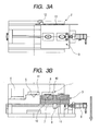
- FIGS. 3A and 3B are views for illustrating a secondary molding process performed by the mold for molding the hollow molded article according to this embodiment.
- FIGS. 1A , 2A , and 3A are schematic views viewed from left side of the mold with a stationary mold being removed therefrom
- FIGS. 1B , 2B , and 3B are schematic views viewed from above the mold.
- the mold is operated from the left side (side of a film formation apparatus 4) in those figures.
- a first mold 1 which is a stationary mold fixed in position and which does not move at a time of mold opening
- a movable mold 2 capable of moving in a direction departing from the stationary mold at the time of mold opening
- a second mold 3 which includes a molding portion for molding divided bodies of the molded article, and which is a slide mold that slides with respect to the stationary mold 1 by a slide mechanism to be described later.
- the movable mold 2 opens rightwards (downwards on the plane) together with the slide mold 3 which is the second mold with respect to the stationary mold with an aid of a mold opening/closing mechanism (not shown).
- the film formation apparatus 4 a stationary mold body molding portion 5, and a stationary mold lens molding portion 6 in a straight line at equal intervals. Further, those are connected to an injection molding machine and there is provided a sprue 50 for supplying a resin to the stationary mold body molding portion 5 and the stationary mold lens molding portion 6.
- the movable mold 2 is provided with the slide mold 3.
- a drive mechanism for sliding the slide mold 3 is structured.
- the slide mold 3 includes a slide mold body molding portion 10 corresponding to the stationary mold body molding portion 5 of the stationary mold 1, and a slide mold lens molding portion 11 corresponding to the stationary mold lens molding portion 6 of the stationary mold 1.
- the slide mold lens molding portion 11 has a cavity 49 for molding a lens portion while coupling with the stationary mold.
- the slide mold body molding portion 10 has a cavity 41 for molding a body portion while coupling with the stationary mold.
- the slide mold is provided to the movable mold 2, but the slide mold may be provided to the stationary mold 1.
- the first mold is the movable mold and the second mold is the slide mold provided onto the stationary mold.
- each of the stationary mold and the movable mold may be provided with the slide mold.
- a ball screw 7 rotates.
- a rotational amount of the ball screw is detected by an encoder (not shown), and a signal thereof is input to a control device (not shown).
- a slider 8 is screwed on the ball screw 7 and the slider 8 is fixed to the slide mold 3.
- the slide mold 3 can be moved.
- a conveying amount is measured by the rotation of the ball screw. According to deviation between the conveying amount input to the control device in advance and the rotational amount of the ball screw detected by the encoder, the slide mold is positioned.
- the ball screw tends to be affected by heat, and a length thereof changes due to the heat. Therefore, a position corresponding to the conveying amount which is set in advance and a position in which the slide mold is actually positioned always vary from each other.
- the conveying amount is corrected.
- a correcting method is described below.
- a guide post 52 and a guide hole 51 as shown in FIG. 5 for positioning the slide mold.
- the guide hole 51 has a tapered insertion opening. Therefore, even when the guide post 52 is inserted while being displaced in some degree, the guide post 52 can be smoothly engaged with the guide hole 51.
- a tapered portion is also provided to the guide post 52 such that the guide post 52 is engaged with the tapered portion of the guide hole 51 when the guide post 52 is completely inserted.
- guide posts 52 are provided on a surface opposing the stationary mold which is to be positioned, in positions opposed to the guide holes 51.
- the guide posts may be mounted on the slide mold and the guide holes may be provided in the stationary mold.
- a signal is sent from a mold opening/closing device to a power supply control device.
- the power supply control device outputs a signal for stopping power supply to the servo motor.
- the guide posts 52 are inserted into the guide holes 51.
- a timing of sending the signal from the mold opening/closing device to the power supply control device is preferably immediately before tip portions of the guide posts are inserted into the guide holes. Due to the positioning by the guide posts, the stationary mold and the slide mold are accurately positioned. Since the power supply to the servo motor is stopped, the current position is corrected as the position corresponding to the conveying amount which is input to the control device in advance.
- the signal is sent from the mold opening/closing device to the power supply control device when the mold opening is completed.
- the power supply control device outputs a signal for starting the power supply to the servo motor, thereby starting the power supply to the servo motor.
- the signal is sent to the power supply control device when the mold opening is completed, but it may be set that the signal is sent when the mold opening is started.
- the positioning of the slide mold 3 may be performed by detecting a position of a scale 13 mounted to the slide mold with a linear encoder 12 mounted to the movable mold 2 through a heat insulating plate (not shown).
- the heat insulating plate may be provided between the linear encoder 12 and the movable mold 2 as a countermeasure against heat, and with this structure, an effect of heat can be prevented.
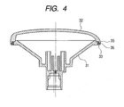
- FIG. 4 shows an example of the hollow molded article molded by the mold of the present invention.
- the hollow molded article of this embodiment includes a body portion 31 and a lens portion 32 inner surfaces of which a film is formed. Butt parts 35 and 36 are allowed to butt on each other. On a periphery of a butt portion, there is formed a space 33. A molten resin injected from the injection molding machine is charged into the space through the sprue. By the resin in the space, the body portion and the lens portion are welded to each other, thereby molding the hollow molded article.
- the servo motor 9 is driven, and by using the ball screw 7, the slide mold 3 is positioned in a mold center portion, which is a molding portion in the primary molding process.
- the slide mold 3 is positioned in a position for the primary mold process that is a first positioning position according to a deviation between the conveying amount input to the control device in advance as described above and the rotational amount of the ball screw detected by the encoder.
- the movable mold 2 is moved to the stationary mold 1 side by the mold opening/closing device, thereby registering the slide mold 3 with the stationary mold 1.
- a signal is sent from the mold opening/closing device to the power supply control device.
- the power supply control device outputs a signal for stopping the power supply to the servo motor.
- the guide posts 52 are inserted into the guide holes 51.
- the stationary mold and the slide mold are accurately positioned. Since the power supply to the servo motor is stopped, the current position is corrected as the position corresponding to the conveying amount which is input to the control device in advance.
- FIGS. 1A and 1B show this state, and the cavities 41 and 49 are formed between the stationary mold 1 and the slide mold 3.
- a molten resin is injected from the injection molding machine mounted to the stationary mold 1.
- the molten resin passes through the sprue 50 of the stationary mold to be charged into the cavities 41 and 49.
- the body portion 31 and the lens portion 32 are respectively formed as divided bodies of the molded article (see FIG. 4 ).
- the movable mold 2 is moved by the mold opening/closing device downwards on the plane, thereby separating the slide mold 3 and the stationary mold 1 to perform the mold opening.
- the body portion 31 remains in the slide mold 3 and is released from the stationary mold 1.
- the lens portion 32 remains in the stationary mold 1 and is released from the slide mold 3.
- a signal is sent to the power supply control device.
- the power supply control device outputs the signal for starting the power supply to the servo motor, thereby starting the power supply to the servo motor.
- the servo motor 9 is driven, and by using the ball screw 7, the slide mold 3 is positioned in a frontward portion of the mold (left side on the plane), which is a molding portion in the film formation process.
- the slide mold 3 is positioned with high accuracy in a position for the film formation process that is a second positioning position according to a deviation between the conveying amount input to the control device in advance and the rotational amount of the ball screw detected by the encoder.
- the movable mold 2 is moved to the stationary mold 1 side by the mold opening/closing device, thereby providing the slide mold body molding portion in the film formation apparatus.
- a signal is sent from the mold opening/closing device to the power supply control device.
- the power supply control device In response to the signal, the power supply control device outputs a signal for stopping the power supply to the servo motor. In the state where the servo motor is unlocked so that the slide mold can freely move, the guide posts 52 are inserted into the guide holes 51.
- FIGS. 2A and 2B show this state.
- the body portion 31 remaining in the slide mold 3 is set in the film formation apparatus.
- the film formation apparatus a typical film formation apparatus is used, so the description thereof is omitted.
- the film formation is performed as follows.
- a vacuum is produced in the film formation apparatus by using a vacuum pump (not shown), high-energy particles are allowed to collide on a surface of a target to cause atoms of the target to be released, thereby performing film formation on the inner surface of the body portion by a sputtering method in which a film is formed on the inner surface of the body portion 31.
- the movable mold 2 is moved by the mold opening/closing device downwards on the plane, thereby separating the slide mold 3 and the film formation apparatus to perform the mold opening.
- a signal is sent to the power supply control device.
- the power supply control device outputs the signal for starting the power supply to the servo motor, thereby starting the power supply to the servo motor.
- the servo motor 9 is driven, and by using the ball screw 7, the slide mold 3 is positioned in a mold back portion (right side on the plane), which is a molding portion in the secondary molding process.
- the slide mold 3 is positioned with high accuracy in a position for a secondary mold process that is a third positioning position according to a deviation between the conveying amount input to the control device in advance and the rotational amount of the ball screw detected by the encoder.
- the movable mold 2 is moved to the stationary mold 1 side by the mold opening/closing device, thereby registering the slide mold 3 with the stationary mold 1.
- the signal is sent from the mold opening/closing device to the power supply control device.
- the power supply control device outputs the signal for stopping the power supply to the servo motor.
- the guide posts 52 are inserted into the guide holes 51.
- the stationary mold and the slide mold are accurately positioned. Since the power supply to the servo motor is stopped, the current position is corrected as the position corresponding to the conveying amount which is input to the control device in advance.
- the mold clamping is performed. The state thereof is shown in FIGS. 3A and 3B .
- the butt parts 35 and 36 of the body portion 31 which is positioned in the slide mold 3 and in which film formation is performed and the lens portion 32 remaining in the stationary mold 1, respectively, are allowed to butt on each other (see FIG. 4 ).
- the molten resin injected from the injection molding machine is charged into the space through the sprue.
- the body portion and the resin portion are welded to each other.
- the stationary mold 1 and the movable mold 2 are opened again by the mold opening/closing device, thereby allowing the slide mold 3 and the stationary mold 1 to be spaced apart from each other.
- the body portion 31 and the lens portion 32 are welded while registering with each other to be completed as the single hollow molded article.
- the movable mold 2 is moved by the mold opening/closing device downwards on the plane, thereby separating the slide mold 3 and the stationary mold 1 to perform the mold opening. As a result, the hollow molded article is removed.
- a signal is sent to the power supply control device.
- the power supply control device outputs the signal for starting the power supply to the servo motor, thereby starting the power supply to the servo motor.
- the servo motor 9 is driven again and the slide mold 3 is positioned in the mold center portion, which is the molding position in the primary molding process. Then, the process moves to the next molding process.
- a speed of the slide mold can be controlled, whereby smooth starting and stopping thereof can be realized with low vibration and low noise.
- the mold matching by using the guide posts by stopping the power supply to the servo motor, the position corresponding to the conveying amount which is set in advance can be corrected. Therefore, by repeating a series of molding process, the hollow molded article can be continuously molded. Further, automation of the molding process is easy and mass production of the hollow molded products can be realized.
Landscapes
- Engineering & Computer Science (AREA)
- Manufacturing & Machinery (AREA)
- Mechanical Engineering (AREA)
- Moulds For Moulding Plastics Or The Like (AREA)
- Injection Moulding Of Plastics Or The Like (AREA)
Applications Claiming Priority (3)
| Application Number | Priority Date | Filing Date | Title |
|---|---|---|---|
| JP2005276428 | 2005-09-22 | ||
| JP2006238455A JP2007112118A (ja) | 2005-09-22 | 2006-09-04 | 中空成形品を成形する金型装置および中空成形品の成形方法 |
| PCT/JP2006/319214 WO2007034979A1 (fr) | 2005-09-22 | 2006-09-21 | Appareil de moule destine au moulage d'un article moule creux et procede de moulage d'un article moule creux |
Publications (1)
| Publication Number | Publication Date |
|---|---|
| EP1927457A1 true EP1927457A1 (fr) | 2008-06-04 |
Family
ID=37889017
Family Applications (1)
| Application Number | Title | Priority Date | Filing Date |
|---|---|---|---|
| EP06810672A Withdrawn EP1927457A1 (fr) | 2005-09-22 | 2006-09-21 | Appareil de moule destine au moulage d'un article moule creux et procede de moulage d'un article moule creux |
Country Status (4)
| Country | Link |
|---|---|
| US (1) | US20070210469A1 (fr) |
| EP (1) | EP1927457A1 (fr) |
| JP (1) | JP2007112118A (fr) |
| WO (1) | WO2007034979A1 (fr) |
Families Citing this family (10)
| Publication number | Priority date | Publication date | Assignee | Title |
|---|---|---|---|---|
| JP2007112119A (ja) * | 2005-09-22 | 2007-05-10 | Igari Mold Kk | 中空成形品を成形する金型装置および中空成形品の成形方法 |
| JP2009023246A (ja) * | 2007-07-20 | 2009-02-05 | Oshima Denki Seisakusho:Kk | 射出成形体の製造方法および射出成形体の製造装置 |
| JP5151649B2 (ja) * | 2008-04-21 | 2013-02-27 | 宇部興産機械株式会社 | 積層品の成形装置及び成形方法 |
| US8794947B2 (en) * | 2011-07-18 | 2014-08-05 | Spirit Aerosystems, Inc. | Translating forming dies |
| CN103144254B (zh) * | 2013-03-06 | 2015-03-25 | 路达(厦门)工业有限公司 | 一种混合出水水龙头成型模具及其成型工艺 |
| JP6590528B2 (ja) * | 2015-05-25 | 2019-10-16 | キヤノン株式会社 | 液体供給部材の製造方法 |
| EP3323582B1 (fr) * | 2016-11-22 | 2018-12-26 | Adval Tech Holding AG | Procédé de fabrication d'un récipient |
| WO2018095747A1 (fr) * | 2016-11-22 | 2018-05-31 | Adval Tech Holding Ag | Procédé de fabrication d'un récipient |
| JP7523035B2 (ja) * | 2020-03-12 | 2024-07-26 | パナソニックIpマネジメント株式会社 | 射出成形品の製造方法 |
| CN112677415B (zh) * | 2020-12-10 | 2022-09-02 | 鸿宝科技(江门)有限公司 | 一种注塑件压紧装置 |
Family Cites Families (19)
| Publication number | Priority date | Publication date | Assignee | Title |
|---|---|---|---|---|
| DE3820459C1 (fr) | 1988-06-16 | 1989-11-09 | Kernforschungsanlage Juelich Gmbh, 5170 Juelich, De | |
| US5730650A (en) * | 1996-08-29 | 1998-03-24 | Progressive Technology Of Wisconsin, Inc. | Food patty molding machine |
| US6451238B1 (en) * | 1998-04-07 | 2002-09-17 | Honda Giken Kogyo Kabushiki Kaisha | Process for producing intake member of resin, and intake member of resin |
| JP3368203B2 (ja) * | 1998-06-02 | 2003-01-20 | ジー・ピー・ダイキョー株式会社 | 合成樹脂製中空体の製造方法及びその装置 |
| JP3430366B2 (ja) * | 1999-09-22 | 2003-07-28 | 日精樹脂工業株式会社 | 射出成形機の圧力検出装置及び圧力検出方法 |
| JP4458391B2 (ja) * | 2000-09-05 | 2010-04-28 | 株式会社大嶋電機製作所 | 中空製品の射出成形方法および成形装置 |
| JP2002248650A (ja) * | 2001-02-23 | 2002-09-03 | Canon Inc | 中空成形品の製造方法及び製造装置 |
| US6450797B1 (en) * | 2001-03-01 | 2002-09-17 | Stackteck Systems Limited | Compact slide actuation mold |
| KR20100085170A (ko) * | 2002-12-25 | 2010-07-28 | 혼다 기켄 고교 가부시키가이샤 | 사출 성형 방법 및 그 장치 |
| JP4367893B2 (ja) * | 2003-01-22 | 2009-11-18 | 本田技研工業株式会社 | 射出成形方法およびその装置 |
| JP3972843B2 (ja) * | 2003-03-18 | 2007-09-05 | 株式会社デンソー | 中空成形品の成形方法およびそれに用いられる成形用金型 |
| US7144537B2 (en) * | 2003-04-25 | 2006-12-05 | Husky Injection Molding Systems Ltd. | Short shuttle molding system for multi-material molding |
| JP4251481B2 (ja) | 2003-05-19 | 2009-04-08 | 株式会社大嶋電機製作所 | 燈体の製造方法および燈体成型用の金型 |
| US7740783B2 (en) * | 2003-05-19 | 2010-06-22 | Mitsuba Corporation | Film forming mold, film forming method using mold, and film forming control system |
| US7571263B2 (en) * | 2004-12-02 | 2009-08-04 | Hitachi Global Storage Technologies Netherlands B.V. | Apparatus and method for monitoring data storage device for usage and warranty |
| JP4616037B2 (ja) * | 2005-03-02 | 2011-01-19 | 株式会社ミツバ | 成形装置における位置決め装置 |
| JP2005276428A (ja) | 2005-04-11 | 2005-10-06 | Toshiba Corp | 不揮発性半導体記憶装置 |
| JP2007112119A (ja) * | 2005-09-22 | 2007-05-10 | Igari Mold Kk | 中空成形品を成形する金型装置および中空成形品の成形方法 |
| JP2006238455A (ja) | 2006-03-07 | 2006-09-07 | Fuji Photo Film Co Ltd | 画像再生方法および装置並びに記録媒体 |
-
2006
- 2006-09-04 JP JP2006238455A patent/JP2007112118A/ja not_active Withdrawn
- 2006-09-21 WO PCT/JP2006/319214 patent/WO2007034979A1/fr not_active Ceased
- 2006-09-21 EP EP06810672A patent/EP1927457A1/fr not_active Withdrawn
-
2007
- 2007-03-16 US US11/687,219 patent/US20070210469A1/en not_active Abandoned
Non-Patent Citations (1)
| Title |
|---|
| See references of WO2007034979A1 * |
Also Published As
| Publication number | Publication date |
|---|---|
| WO2007034979A1 (fr) | 2007-03-29 |
| JP2007112118A (ja) | 2007-05-10 |
| US20070210469A1 (en) | 2007-09-13 |
Similar Documents
| Publication | Publication Date | Title |
|---|---|---|
| US20070210469A1 (en) | Mold apparatus for producing hollow molded article and method of producing hollow molded article | |
| EP3000577B1 (fr) | Machine de moulage par injection pour moulage de deux matériaux et procédés pour son contrôle | |
| CN102371661B (zh) | 脱模装置和注模机 | |
| US5221538A (en) | Rotational injection molding machine having a plurality of combinations of male and female dies | |
| KR20080013987A (ko) | 성형조건 설정방법 | |
| CN118322479A (zh) | 一种具有汽车脱模结构的注塑模具 | |
| US20070212440A1 (en) | Mold apparatus for producing hollow molded article, and method for producing hollow molded article | |
| JP5265219B2 (ja) | インサート成形方法 | |
| JP3706169B2 (ja) | 射出成形用金型 | |
| CN101267927A (zh) | 用于生产空心模制品的模具装置以及生产空心模制品的方法 | |
| CN103862643A (zh) | 一种微型注塑机 | |
| US11602877B2 (en) | Method for manufacturing mold and mold | |
| CN215396683U (zh) | 可多次合模的肘杆式合模装置 | |
| JP2002192563A (ja) | 金型交換方法および金型交換装置 | |
| JP2011136442A (ja) | 型締装置及びその制御方法 | |
| US20090214687A1 (en) | Injection Molding Machine | |
| JP2009143062A (ja) | 薄肉射出成形品の成形金型機構。 | |
| US20060269647A1 (en) | Molding metal mold and method for producing a molded item | |
| US20230339146A1 (en) | Mold manufacturing method and mold | |
| CN213733132U (zh) | 模具装置 | |
| CN101267925A (zh) | 用于生产空心模制品的模具装置以及用于生产空心模制品的方法 | |
| JP2008173823A (ja) | 射出成形機 | |
| JPH0732427A (ja) | 射出成形装置および射出成形方法 | |
| JP2009006661A (ja) | 成形方法 | |
| WO2002102570A1 (fr) | Procede de production de lentille plastique et presse a injecter |
Legal Events
| Date | Code | Title | Description |
|---|---|---|---|
| PUAI | Public reference made under article 153(3) epc to a published international application that has entered the european phase |
Free format text: ORIGINAL CODE: 0009012 |
|
| 17P | Request for examination filed |
Effective date: 20080227 |
|
| AK | Designated contracting states |
Kind code of ref document: A1 Designated state(s): AT BE BG CH CY CZ DE DK EE ES FI FR GB GR HU IE IS IT LI LT LU LV MC NL PL PT RO SE SI SK TR |
|
| STAA | Information on the status of an ep patent application or granted ep patent |
Free format text: STATUS: THE APPLICATION HAS BEEN WITHDRAWN |
|
| 18W | Application withdrawn |
Effective date: 20100709 |