EP1927701A1 - Schaufel für ein Ladefahrzeug - Google Patents
Schaufel für ein Ladefahrzeug Download PDFInfo
- Publication number
- EP1927701A1 EP1927701A1 EP07010796A EP07010796A EP1927701A1 EP 1927701 A1 EP1927701 A1 EP 1927701A1 EP 07010796 A EP07010796 A EP 07010796A EP 07010796 A EP07010796 A EP 07010796A EP 1927701 A1 EP1927701 A1 EP 1927701A1
- Authority
- EP
- European Patent Office
- Prior art keywords
- bucket
- rotary motor
- blade
- implement
- loading vehicle
- Prior art date
- Legal status (The legal status is an assumption and is not a legal conclusion. Google has not performed a legal analysis and makes no representation as to the accuracy of the status listed.)
- Granted
Links
Images

Classifications
-
- E—FIXED CONSTRUCTIONS
- E02—HYDRAULIC ENGINEERING; FOUNDATIONS; SOIL SHIFTING
- E02F—DREDGING; SOIL-SHIFTING
- E02F3/00—Dredgers; Soil-shifting machines
- E02F3/04—Dredgers; Soil-shifting machines mechanically-driven
- E02F3/28—Dredgers; Soil-shifting machines mechanically-driven with digging tools mounted on a dipper- or bucket-arm, i.e. there is either one arm or a pair of arms, e.g. dippers, buckets
- E02F3/36—Component parts
- E02F3/40—Dippers; Buckets ; Grab devices, e.g. manufacturing processes for buckets, form, geometry or material of buckets
- E02F3/402—Dippers; Buckets ; Grab devices, e.g. manufacturing processes for buckets, form, geometry or material of buckets with means for facilitating the loading thereof, e.g. conveyors
- E02F3/404—Dippers; Buckets ; Grab devices, e.g. manufacturing processes for buckets, form, geometry or material of buckets with means for facilitating the loading thereof, e.g. conveyors comprising two parts movable relative to each other, e.g. for gripping
-
- E—FIXED CONSTRUCTIONS
- E02—HYDRAULIC ENGINEERING; FOUNDATIONS; SOIL SHIFTING
- E02F—DREDGING; SOIL-SHIFTING
- E02F3/00—Dredgers; Soil-shifting machines
- E02F3/04—Dredgers; Soil-shifting machines mechanically-driven
- E02F3/28—Dredgers; Soil-shifting machines mechanically-driven with digging tools mounted on a dipper- or bucket-arm, i.e. there is either one arm or a pair of arms, e.g. dippers, buckets
- E02F3/30—Dredgers; Soil-shifting machines mechanically-driven with digging tools mounted on a dipper- or bucket-arm, i.e. there is either one arm or a pair of arms, e.g. dippers, buckets with a dipper-arm pivoted on a cantilever beam, i.e. boom
- E02F3/308—Dredgers; Soil-shifting machines mechanically-driven with digging tools mounted on a dipper- or bucket-arm, i.e. there is either one arm or a pair of arms, e.g. dippers, buckets with a dipper-arm pivoted on a cantilever beam, i.e. boom working outwardly
-
- E—FIXED CONSTRUCTIONS
- E02—HYDRAULIC ENGINEERING; FOUNDATIONS; SOIL SHIFTING
- E02F—DREDGING; SOIL-SHIFTING
- E02F3/00—Dredgers; Soil-shifting machines
- E02F3/04—Dredgers; Soil-shifting machines mechanically-driven
- E02F3/28—Dredgers; Soil-shifting machines mechanically-driven with digging tools mounted on a dipper- or bucket-arm, i.e. there is either one arm or a pair of arms, e.g. dippers, buckets
- E02F3/36—Component parts
- E02F3/42—Drives for dippers, buckets, dipper-arms or bucket-arms
- E02F3/422—Drive systems for bucket-arms, front-end loaders, dumpers or the like
-
- E—FIXED CONSTRUCTIONS
- E02—HYDRAULIC ENGINEERING; FOUNDATIONS; SOIL SHIFTING
- E02F—DREDGING; SOIL-SHIFTING
- E02F3/00—Dredgers; Soil-shifting machines
- E02F3/04—Dredgers; Soil-shifting machines mechanically-driven
- E02F3/28—Dredgers; Soil-shifting machines mechanically-driven with digging tools mounted on a dipper- or bucket-arm, i.e. there is either one arm or a pair of arms, e.g. dippers, buckets
- E02F3/36—Component parts
- E02F3/42—Drives for dippers, buckets, dipper-arms or bucket-arms
- E02F3/425—Drive systems for dipper-arms, backhoes or the like
-
- E—FIXED CONSTRUCTIONS
- E02—HYDRAULIC ENGINEERING; FOUNDATIONS; SOIL SHIFTING
- E02F—DREDGING; SOIL-SHIFTING
- E02F3/00—Dredgers; Soil-shifting machines
- E02F3/04—Dredgers; Soil-shifting machines mechanically-driven
- E02F3/96—Dredgers; Soil-shifting machines mechanically-driven with arrangements for alternate or simultaneous use of different digging elements
- E02F3/962—Mounting of implements directly on tools already attached to the machine
Definitions
- the invention relates to a working device equipped with a bucket for a loading vehicle.
- Conventional loading vehicles such as wheel loaders, can be provided with different types of blades.
- buckets for loading vehicles may have a working device, such as a hold-down or a loading tongs.
- hydraulic cylinders In known loading vehicles one or more hydraulic cylinders are used for this purpose. These hydraulic cylinders are attached to the bucket or implement. A disadvantage of such hydraulic cylinders is that they are constantly exposed to heavy loads due to dust, dirt, moisture and often the risk of damage. The wear of the exposed sliding surfaces and the seals of the hydraulic cylinders as well as the expense of maintenance and repair are correspondingly high.
- the present invention seeks to provide a scoop equipped with a working device for a loading vehicle, which has a lower wear. This object is achieved by a blade according to claim 1.
- a bucket for a loading vehicle equipped with a working device, the bucket having a rotary motor.
- rotary motors and thus appropriately equipped blades are insensitive to the stresses occurring under normal conditions of use, such as dust, dirt, moisture and damage. Correspondingly lower is the wear of the rotary motors and the expense of repairs.
- the space requirement is very low in the very compact design rotary motors. Furthermore, a constant torque during opening and closing of the blade can be made possible by the rotary motor.
- the bucket and the implement may each be connected to the rotary motor.
- the rotary motor can be firmly connected to the blade and / or the implement.
- the rotary motor can be connected in particular rotationally fixed to the blade and / or the implement. In this way, the wear of supply and discharge lines to the rotary motor can be reduced.
- the rotary motor can in particular be detachably connected, for example by means of screws, or non-detachably, for example by means of welding or riveting, to the blade and / or the implement.
- the working device can be connected in particular via the rotary motor or by means of the rotary motor with the blade.
- the rotary motor can move the bucket and the implement relative to each other.
- the rotary motor can be arranged such that the blade and the implement can be moved relative to one another through it.
- the implement may in particular be a hold-down device, a loading tongs, a gripping fork, a support frame or a folding part.
- the support frame may be a support frame for the bucket.
- the rotary motor can be driven hydraulically and / or pneumatically and / or electrically.
- the rotary motor can be controlled hydraulically and / or pneumatically and / or electrically.
- the blades described above may in particular be a high-tilt bucket, a side-tipper bucket, a loading fork with hold-down device, a hold-down bucket or a folding bucket, in particular a 4-in-1 bucket.
- the implement may be pivotable about a pivot axis with respect to the bucket.
- the rotary motor can be arranged coaxially and / or in extension to the pivot axis.
- the drive shaft of the rotary motor can be arranged coaxially with the pivot axis. This allows in particular a compact arrangement of the rotary motor on the Shovel.
- the rotary motor can for example be integrated in the blade or arranged inside the blade.
- the blades described above may in particular comprise more than one rotary motor.
- the implement with respect to the blade can be pivoted about more than one pivot axis and the drive shaft in each case a rotary motor can be arranged coaxially to one of the pivot axes.
- the invention further provides a loading vehicle comprising one of the previously described blades.
- the loading vehicle may in particular be a front loader, a telescopic loader or a wheel loader.
- the invention provides the use of a rotary motor for a work tool-equipped bucket for a loading vehicle.
- the blade may in particular be one of the previously described blades.
- the bucket and the implement may each be connected to the rotary motor.
- the invention provides the use of any of the previously described buckets for a loading vehicle, in particular a front loader, a telescopic loader or a wheel loader.
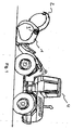
- FIG. 1 Illustrated wheel loader 4 is equipped with a hold-down bucket.
- a blade 1 is equipped with a hold-down 2.
- the hold-down device 2 is pivotable with respect to the blade 1 about a pivot axis perpendicular to the plane of the drawing.
- the rotary motor 3 is arranged on the blade 1 or integrated into it so that its drive shaft is arranged coaxially to the pivot axis.
- the rotary motor is in particular rotatably connected to the blade.
- the hold-down device 2 is thus connected to the blade via the rotary motor, wherein the rotary motor is arranged such that the blade and the hold-down device are movable relative to one another.
- One of the FIG. 1 corresponding arrangement can also be provided with a loading fork with hold-down (sometimes called pliers).
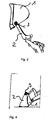
- FIG. 2 schematically illustrates an example of an alternative blade according to the invention in the form of a sokippschaufel.
- the blade 1 is pivotally connected to a support frame as an implement.
- the rotary motor 3 is connected to the blade 1 and the support frame 2 in such a way that its drive shaft is arranged coaxially with the pivot axis. Again, a compact and low-wear construction is achieved by the rotary motor.
- FIG. 3 is an example of a high tilt bucket illustrated, in which, analogous to the case in FIG. 2 , a support frame 2 is pivotally connected via a rotary motor 3 with a blade 1. Again, the rotary motor is arranged coaxially to the pivot axis on the blade.
- Folding bucket sometimes also referred to as a 4-in-1 bucket, comprises a bucket 1, which is equipped with a folding part 2, which is pivotable relative to the bucket 1 by means of a rotary motor.
- the rotary motors can be hydraulically, pneumatically and / or electrically controlled and / or driven.
Landscapes
- Engineering & Computer Science (AREA)
- Mechanical Engineering (AREA)
- Mining & Mineral Resources (AREA)
- Civil Engineering (AREA)
- General Engineering & Computer Science (AREA)
- Structural Engineering (AREA)
- Shovels (AREA)
- Forklifts And Lifting Vehicles (AREA)
- Load-Engaging Elements For Cranes (AREA)
Abstract
Description
- Die Erfindung betrifft eine mit einem Arbeitsgerät ausgestattete Schaufel für ein Ladefahrzeug.
- Herkömmliche Ladefahrzeuge, beispielsweise Radlader, können mit verschiedenen Arten von Schaufeln versehen werden. Beispielsweise können solche Schaufeln für Ladefahrzeuge ein Arbeitsgerät aufweisen, wie beispielsweise einen Niederhalter oder eine Ladezange.
- Beim Arbeiten mit derartigen Schaufeln werden dann die Arbeitsgeräte relativ zur Schaufel bewegt, insbesondere geschwenkt.
- Bei bekannten Ladefahrzeugen werden hierfür ein oder mehrere Hydraulikzylinder verwendet. Diese Hydraulikzylinder sind an der Schaufel bzw. dem Arbeitsgerät befestigt. Ein Nachteil derartiger Hydraulikzylinder besteht darin, dass sie ständig, einsatzbedingt starken Belastungen durch Staub, Schmutz, Feuchtigkeit und nicht selten der Gefahr der Beschädigung ausgesetzt sind. Entsprechend groß ist der Verschleiß der freiliegenden Gleitflächen und der Dichtungen der Hydraulikzylinder sowie der Aufwand für Wartung und Reparatur.
- Angesichts dessen liegt der Erfindung die Aufgabe zugrunde, eine mit einem Arbeitsgerät ausgestattete Schaufel für ein Ladefahrzeug bereitzustellen, die einen geringeren Verschleiß aufweist. Diese Aufgabe wird gelöst durch eine Schaufel gemäß Anspruch 1.
- Erfindungsgemäß wird eine Schaufel für ein Ladefahrzeug, ausgestattet mit einem Arbeitsgerät, bereitgestellt, wobei die Schaufel einen Drehmotor aufweist.
- Aufgrund ihres abgeschlossenen Aufbaus sind Drehmotoren und damit auch entsprechend ausgerüstete Schaufeln unempfindlich gegen die bei üblichen Einsatzbedingungen auftretenden Belastungen, wie Staub, Schmutz, Feuchtigkeit sowie gegen Beschädigung. Entsprechend geringer ist der Verschleiß der Drehmotoren und der Aufwand für Reparaturen. Der Platzbedarf ist bei den sehr kompakt bauenden Drehmotoren sehr gering. Weiterhin kann durch den Drehmotor ein gleichbleibendes Drehmoment beim Öffnen und Schließen der Schaufel ermöglicht werden.
- Die Schaufel und das Arbeitsgerät können jeweils mit dem Drehmotor verbunden sein. Insbesondere kann der Drehmotor fest mit der Schaufel und/oder dem Arbeitsgerät verbunden sein. Der Drehmotor kann dabei insbesondere drehfest mit der Schaufel und/oder dem Arbeitsgerät verbunden sein. Auf diese Weise lässt sich auch der Verschleiß von Zu- und Ableitungen zum Drehmotor verringern.
- Bei herkömmlichen Hydraulikzylindern bewegen sich aufgrund der Zylinder die entsprechenden Hydraulikleitungen, sodass es insbesondere zu einem Verschleiß aufgrund Scheuerns kommen kann, was bei den beschriebenen, mit der Schaufel bzw. dem Arbeitsgerät verbundenen Drehmotoren nicht der Fall ist.
- Der Drehmotor kann insbesondere lösbar, beispielsweise mittels Schrauben, oder unlösbar, beispielsweise mittels Schweißen oder Nieten, mit der Schaufel und/oder dem Arbeitsgerät verbunden sein. Das Arbeitsgerät kann insbesondere über den Drehmotor oder mittels des Drehmotors mit der Schaufel verbunden sein.
- Bei den zuvor beschriebenen Schaufeln kann der Drehmotor die Schaufel und das Arbeitsgerät relativ zueinander bewegen. Der Drehmotor kann mit anderen Worten derart angeordnet sein, dass durch ihn die Schaufel und das Arbeitsgerät relativ zueinander bewegbar sind.
- Das Arbeitsgerät kann insbesondere ein Niederhalter, eine Ladezange, eine Greifgabel, ein Trägerrahmen oder ein Klappteil sein. Bei dem Trägerrahmen kann es sich um einen Trägerrahmen für die Schaufel handeln.
- Der Drehmotor kann hydraulisch und/oder pneumatisch und/oder elektrisch angetrieben werden. Der Drehmotor kann hydraulisch und/oder pneumatisch und/oder elektrisch gesteuert werden.
- Bei den zuvor beschriebenen Schaufeln kann es sich insbesondere um eine Hochkippschaufel, eine Seitenkippschaufel, eine Ladegabel mit Niederhalter, eine Niederhalterschaufel oder eine Klappschaufel, insbesondere eine 4-in-1-Schaufel, handeln.
- Das Arbeitsgerät kann bezüglich der Schaufel um eine Schwenkachse schwenkbar sein. Dabei kann der Drehmotor koaxial und/oder in Verlängerung zu der Schwenkachse angeordnet sein. Die Antriebswelle des Drehmotors kann koaxial zu der Schwenkachse angeordnet sein. Dies erlaubt insbesondere eine kompakte Anordnung des Drehmotors an der Schaufel. Der Drehmotor kann beispielsweise in der Schaufel integriert bzw. innerhalb der Schaufel angeordnet sein.
- Die zuvor beschriebenen Schaufeln können insbesondere mehr als einen Drehmotor umfassen. Dabei kann dann beispielsweise das Arbeitsgerät bezüglich der Schaufel um mehr als eine Schwenkachse schwenkbar sein und die Antriebswelle jeweils eines Drehmotors koaxial zu einer der Schwenkachsen angeordnet sein.
- Die Erfindung stellt weiterhin ein Ladefahrzeug umfassend eine der zuvor beschriebenen Schaufeln bereit. Das Ladefahrzeug kann insbesondere ein Frontlader, ein Teleskoplader oder ein Radlader sein.
- Weiterhin stellt die Erfindung die Verwendung eines Drehmotors für eine mit einem Arbeitsgerät ausgestattete Schaufel für ein Ladefahrzeug bereit. Bei der Schaufel kann es sich insbesondere um eine der zuvor beschriebenen Schaufeln handeln. So können die Schaufel und das Arbeitsgerät beispielsweise jeweils mit dem Drehmotor verbunden sein.
- Zusätzlich stellt die Erfindung die Verwendung einer der zuvor beschriebenen Schaufeln für ein Ladefahrzeug, insbesondere einen Frontlader, einen Teleskoplader oder ein Radlader bereit.
- Weitere Merkmale und Vorteile werden nachfolgend unter Bezugnahme auf die Figuren beschrieben. Es zeigt:
- Figur 1
- ein Beispiel eines Radladers mit einem Beispiel einer erfindungsgemäßen Niederhalterschaufel;
- Figur 2
- ein Beispiel einer erfindungsgemäßen Seitenkippschaufel;
- Figur 3
- ein Beispiel einer erfindungsgemäßen Hochkippschaufel; und
- Figur 4
- ein Beispiel einer erfindungsgemäßen Klappschaufel.
- Der in
Figur 1 illustrierte Radlader 4 ist mit einer Niederhalterschaufel ausgerüstet. Dabei ist eine Schaufel 1 mit einem Niederhalter 2 ausgestattet. Der Niederhalter 2 ist bezüglich der Schaufel 1 um eine senkrecht zur Zeichnungsebene stehende Schwenkachse schwenkbar. - Der Drehmotor 3 ist derart an der Schaufel 1 angeordnet bzw. in diese integriert, dass seine Antriebswelle koaxial zu der Schwenkachse angeordnet ist. Der Drehmotor ist insbesondere drehfest mit der Schaufel verbunden. In dem gezeigten Beispiel ist somit der Niederhalter 2 über den Drehmotor mit der Schaufel verbunden, wobei der Drehmotor derart angeordnet ist, dass die Schaufel und der Niederhalter relativ zueinander bewegbar sind. Eine der
Figur 1 entsprechende Anordnung kann auch bei einer Ladegabel mit Niederhalter (manchmal auch Zange genannt) vorgesehen sein. -
Figur 2 illustriert schematisch ein Beispiel einer alternativen erfindungsgemäßen Schaufel in Form einer Seitenkippschaufel. Hier ist die Schaufel 1 mit einem Trägerrahmen als Arbeitsgerät schwenkbar verbunden. Der Drehmotor 3 ist derart mit der Schaufel 1 und dem Trägerrahmen 2 verbunden, dass seine Antriebswelle koaxial zur Schwenkachse angeordnet ist. Auch hier wird durch den Drehmotor eine kompakte und verschleißarme Bauweise erzielt. - In
Figur 3 ist ein Beispiel einer Hochkippschaufel illustriert, bei der, analog zu dem Fall inFigur 2 , ein Trägerrahmen 2 schwenkbar über einen Drehmotor 3 mit einer Schaufel 1 verbunden ist. Auch hier ist der Drehmotor koaxial zur Schwenkachse an der Schaufel angeordnet. - Das Beispiel der in
Figur 4 illustrierten Klappschaufel, manchmal auch 4-in-1-Schaufel genannt, umfasst eine Schaufel 1, die mit einem Klappteil 2 ausgestattet ist, das mittels eines Drehmotors bezüglich der Schaufel 1 schwenkbar ist. - In den gezeigten Beispielen können die Drehmotoren hydraulisch, pneumatisch und/oder elektrisch gesteuert und/oder angetrieben werden.
Claims (12)
- Schaufel (1) für ein Ladefahrzeug, ausgestattet mit einem Arbeitsgerät (2), wobei die Schaufel einen Drehmotor (3) aufweist.
- Schaufel nach Anspruch 1, wobei die Schaufel und das Arbeitsgerät jeweils mit dem Drehmotor verbunden sind.
- Schaufel nach Anspruch 1 oder 2, wobei der Drehmotor fest mit der Schaufel und/oder dem Arbeitsgerät verbunden ist.
- Schaufel nach einem der vorangegangenen Ansprüche, wobei der Drehmotor die Schaufel und das Arbeitsgerät relativ zueinander bewegt.
- Schaufel nach einem der vorangegangenen Ansprüche, wobei das Arbeitsgerät ein Niederhalter, eine Ladezange, eine Greifgabel, ein Trägerrahmen oder ein Klappteil ist.
- Schaufel nach einem der vorangegangenen Ansprüche, wobei der Drehmotor hydraulisch und/oder pneumatisch und/oder elektrisch angetrieben und gesteuert wird.
- Schaufel nach einem der vorangegangenen Ansprüche, wobei die Schaufel eine Hochkippschaufel, eine Seitenkippschaufel, eine Ladegabel mit Niederhalter, eine Niederhalterschaufel, oder eine Klappschaufel ist.
- Schaufel nach einem der vorangegangenen Ansprüche, wobei das Arbeitsgerät bezüglich der Schaufel um eine Schwenkachse schwenkbar ist und die Antriebswelle des Drehmotors- koaxial zu der Schwenkachse angeordnet ist.
- Ladefahrzeug umfassend eine Schaufel nach einem der vorangegangenen Ansprüche.
- Ladefahrzeug nach Anspruch 9, wobei das Ladefahrzeug ein Frontlader, ein Teleskoplader oder ein Radlader ist.
- Verwendung eines Drehmotors für eine mit einem Arbeitsgerät ausgestattete Schaufel für ein Ladefahrzeug.
- Verwendung einer Schaufel nach einem der Ansprüche 1 - 8 für ein Ladefahrzeug, insbesondere einen Frontlader, einen Teleskoplader oder einen Radlader.
Applications Claiming Priority (1)
| Application Number | Priority Date | Filing Date | Title |
|---|---|---|---|
| DE202006018085U DE202006018085U1 (de) | 2006-11-28 | 2006-11-28 | Schaufel für Ladefahrzeuge |
Publications (2)
| Publication Number | Publication Date |
|---|---|
| EP1927701A1 true EP1927701A1 (de) | 2008-06-04 |
| EP1927701B1 EP1927701B1 (de) | 2010-08-04 |
Family
ID=37763707
Family Applications (1)
| Application Number | Title | Priority Date | Filing Date |
|---|---|---|---|
| EP07010796A Active EP1927701B1 (de) | 2006-11-28 | 2007-05-31 | Radlader mit einer Schaufel und Verwendung einer Schaufel für einen Radlader. |
Country Status (4)
| Country | Link |
|---|---|
| EP (1) | EP1927701B1 (de) |
| AT (1) | ATE476559T1 (de) |
| DE (3) | DE202006018085U1 (de) |
| ES (1) | ES2367378T3 (de) |
Citations (8)
| Publication number | Priority date | Publication date | Assignee | Title |
|---|---|---|---|---|
| GB791648A (en) * | 1955-08-25 | 1958-03-05 | Poclain Atel | Improvements in mechanical shovels |
| US3343693A (en) * | 1965-12-23 | 1967-09-26 | Carl P Becker | Bucket control mechanism for power shovels |
| JPH08151654A (ja) * | 1994-11-28 | 1996-06-11 | Komatsu Ltd | 作業機の揺動装置 |
| JPH11131522A (ja) * | 1997-11-04 | 1999-05-18 | Katsunori Tanada | 掘削機におけるバケット等の作業具の作動装置 |
| WO2001038649A1 (en) * | 1999-11-23 | 2001-05-31 | 1994 Weyer Family Limited Partnership | Hydraulic collection tool |
| WO2003018917A1 (de) * | 2001-08-21 | 2003-03-06 | Rädlinger Maschinen- und Anlagenbau GmbH | Baumaschine mit hydraulischem drehmotor |
| US20040000811A1 (en) * | 2002-06-28 | 2004-01-01 | 1994 Weyer Family Limited Partnership | Timed rotation tool assembly and actuator |
| DE10339176A1 (de) * | 2003-08-22 | 2005-03-10 | Thomas Sauer | Hydraulikbagger und -krane |
-
2006
- 2006-11-28 DE DE202006018085U patent/DE202006018085U1/de not_active Expired - Lifetime
-
2007
- 2007-05-31 EP EP07010796A patent/EP1927701B1/de active Active
- 2007-05-31 ES ES07010796T patent/ES2367378T3/es active Active
- 2007-05-31 DE DE502007004628T patent/DE502007004628D1/de active Active
- 2007-05-31 DE DE202007019024U patent/DE202007019024U1/de not_active Expired - Lifetime
- 2007-05-31 AT AT07010796T patent/ATE476559T1/de active
Patent Citations (8)
| Publication number | Priority date | Publication date | Assignee | Title |
|---|---|---|---|---|
| GB791648A (en) * | 1955-08-25 | 1958-03-05 | Poclain Atel | Improvements in mechanical shovels |
| US3343693A (en) * | 1965-12-23 | 1967-09-26 | Carl P Becker | Bucket control mechanism for power shovels |
| JPH08151654A (ja) * | 1994-11-28 | 1996-06-11 | Komatsu Ltd | 作業機の揺動装置 |
| JPH11131522A (ja) * | 1997-11-04 | 1999-05-18 | Katsunori Tanada | 掘削機におけるバケット等の作業具の作動装置 |
| WO2001038649A1 (en) * | 1999-11-23 | 2001-05-31 | 1994 Weyer Family Limited Partnership | Hydraulic collection tool |
| WO2003018917A1 (de) * | 2001-08-21 | 2003-03-06 | Rädlinger Maschinen- und Anlagenbau GmbH | Baumaschine mit hydraulischem drehmotor |
| US20040000811A1 (en) * | 2002-06-28 | 2004-01-01 | 1994 Weyer Family Limited Partnership | Timed rotation tool assembly and actuator |
| DE10339176A1 (de) * | 2003-08-22 | 2005-03-10 | Thomas Sauer | Hydraulikbagger und -krane |
Also Published As
| Publication number | Publication date |
|---|---|
| ATE476559T1 (de) | 2010-08-15 |
| EP1927701B1 (de) | 2010-08-04 |
| DE502007004628D1 (de) | 2010-09-16 |
| DE202006018085U1 (de) | 2007-02-08 |
| ES2367378T3 (es) | 2011-11-02 |
| DE202007019024U1 (de) | 2010-03-11 |
Similar Documents
| Publication | Publication Date | Title |
|---|---|---|
| DE60034062T2 (de) | Hydraulisches sammelwerkzeug | |
| DE202010018347U1 (de) | Kippbare Werkzeuganordnung | |
| EP2177670B1 (de) | Oberwagenkonstruktion eines verfahrbaren Arbeitsgerätes | |
| DE112008002965T5 (de) | Gelenkverbindungsanordnung zum Verbinden eines Werkzeugs mit dem Rahmen einer Arbeitsmaschine | |
| DE69324353T2 (de) | Universeller Brecher | |
| EP1621682B1 (de) | Umschlaggerät | |
| EP0887300A2 (de) | Hub-Dreh-Vorrichtung zur Aufnahme eines Kraftfahrzeuges | |
| EP2403998B1 (de) | Anbaugerät für baumaschinen | |
| DE2411051A1 (de) | Arbeitsmaschine fuer tiefbauarbeiten, insbesondere schaufellader | |
| EP1927701B1 (de) | Radlader mit einer Schaufel und Verwendung einer Schaufel für einen Radlader. | |
| DE102013006307B4 (de) | Baumaschine und verfahren zum betreiben der baumaschine | |
| DE102018114314B4 (de) | Winkelstück und Hebevorrichtung | |
| EP3219660B1 (de) | Kran, welcher auf einer fahrbaren arbeitsmaschine für forstarbeit anzubringen ist | |
| EP0557600B1 (de) | Zweigeteilter schwenkbarer Löffel | |
| EP1329414A1 (de) | Materialumschlaggerät | |
| EP0218899B2 (de) | Abbruchschere | |
| DE29621253U1 (de) | Schwenkadapter | |
| DE60205246T2 (de) | Brechvorrichtung | |
| DE102014204551A1 (de) | Arbeitsfahrzeug und Verfahren | |
| EP1748112B1 (de) | Anbauwerkzeug für Baumaschinen | |
| DE102022120932A1 (de) | Anbauvorrichtung für einen Stiel eines Baggers | |
| DE202007016913U1 (de) | Greifer | |
| EP2305896B1 (de) | Mobile Baumaschine mit einer an einem Schild ankoppelbaren Zusatzeinrichtung | |
| AT272199B (de) | Materialfördergerät | |
| DE102022125077A1 (de) | Arbeitsgerät für einen Bagger |
Legal Events
| Date | Code | Title | Description |
|---|---|---|---|
| PUAI | Public reference made under article 153(3) epc to a published international application that has entered the european phase |
Free format text: ORIGINAL CODE: 0009012 |
|
| 17P | Request for examination filed |
Effective date: 20070918 |
|
| AK | Designated contracting states |
Kind code of ref document: A1 Designated state(s): AT BE BG CH CY CZ DE DK EE ES FI FR GB GR HU IE IS IT LI LT LU LV MC MT NL PL PT RO SE SI SK TR |
|
| AX | Request for extension of the european patent |
Extension state: AL BA HR MK RS |
|
| 17Q | First examination report despatched |
Effective date: 20080613 |
|
| AKX | Designation fees paid |
Designated state(s): AT BE BG CH CY CZ DE DK EE ES FI FR GB GR HU IE IS IT LI LT LU LV MC MT NL PL PT RO SE SI SK TR |
|
| GRAP | Despatch of communication of intention to grant a patent |
Free format text: ORIGINAL CODE: EPIDOSNIGR1 |
|
| RTI1 | Title (correction) |
Free format text: WHEELED LOADER EQUIPPED WITH A LOADING BUCKET AND USE OF A LOADING BUCKET FOR A WHEELED LOADER. |
|
| GRAS | Grant fee paid |
Free format text: ORIGINAL CODE: EPIDOSNIGR3 |
|
| GRAA | (expected) grant |
Free format text: ORIGINAL CODE: 0009210 |
|
| AK | Designated contracting states |
Kind code of ref document: B1 Designated state(s): AT BE BG CH CY CZ DE DK EE ES FI FR GB GR HU IE IS IT LI LT LU LV MC MT NL PL PT RO SE SI SK TR |
|
| REG | Reference to a national code |
Ref country code: GB Ref legal event code: FG4D Free format text: NOT ENGLISH |
|
| REG | Reference to a national code |
Ref country code: CH Ref legal event code: EP |
|
| REG | Reference to a national code |
Ref country code: IE Ref legal event code: FG4D Free format text: LANGUAGE OF EP DOCUMENT: GERMAN |
|
| REF | Corresponds to: |
Ref document number: 502007004628 Country of ref document: DE Date of ref document: 20100916 Kind code of ref document: P |
|
| REG | Reference to a national code |
Ref country code: NL Ref legal event code: T3 |
|
| REG | Reference to a national code |
Ref country code: SE Ref legal event code: TRGR |
|
| LTIE | Lt: invalidation of european patent or patent extension |
Effective date: 20100804 |
|
| PG25 | Lapsed in a contracting state [announced via postgrant information from national office to epo] |
Ref country code: LT Free format text: LAPSE BECAUSE OF FAILURE TO SUBMIT A TRANSLATION OF THE DESCRIPTION OR TO PAY THE FEE WITHIN THE PRESCRIBED TIME-LIMIT Effective date: 20100804 Ref country code: FI Free format text: LAPSE BECAUSE OF FAILURE TO SUBMIT A TRANSLATION OF THE DESCRIPTION OR TO PAY THE FEE WITHIN THE PRESCRIBED TIME-LIMIT Effective date: 20100804 |
|
| PG25 | Lapsed in a contracting state [announced via postgrant information from national office to epo] |
Ref country code: BG Free format text: LAPSE BECAUSE OF FAILURE TO SUBMIT A TRANSLATION OF THE DESCRIPTION OR TO PAY THE FEE WITHIN THE PRESCRIBED TIME-LIMIT Effective date: 20101104 Ref country code: CY Free format text: LAPSE BECAUSE OF FAILURE TO SUBMIT A TRANSLATION OF THE DESCRIPTION OR TO PAY THE FEE WITHIN THE PRESCRIBED TIME-LIMIT Effective date: 20100804 Ref country code: IS Free format text: LAPSE BECAUSE OF FAILURE TO SUBMIT A TRANSLATION OF THE DESCRIPTION OR TO PAY THE FEE WITHIN THE PRESCRIBED TIME-LIMIT Effective date: 20101204 Ref country code: PL Free format text: LAPSE BECAUSE OF FAILURE TO SUBMIT A TRANSLATION OF THE DESCRIPTION OR TO PAY THE FEE WITHIN THE PRESCRIBED TIME-LIMIT Effective date: 20100804 Ref country code: PT Free format text: LAPSE BECAUSE OF FAILURE TO SUBMIT A TRANSLATION OF THE DESCRIPTION OR TO PAY THE FEE WITHIN THE PRESCRIBED TIME-LIMIT Effective date: 20101206 Ref country code: SI Free format text: LAPSE BECAUSE OF FAILURE TO SUBMIT A TRANSLATION OF THE DESCRIPTION OR TO PAY THE FEE WITHIN THE PRESCRIBED TIME-LIMIT Effective date: 20100804 |
|
| REG | Reference to a national code |
Ref country code: IE Ref legal event code: FD4D |
|
| PG25 | Lapsed in a contracting state [announced via postgrant information from national office to epo] |
Ref country code: LV Free format text: LAPSE BECAUSE OF FAILURE TO SUBMIT A TRANSLATION OF THE DESCRIPTION OR TO PAY THE FEE WITHIN THE PRESCRIBED TIME-LIMIT Effective date: 20100804 Ref country code: GR Free format text: LAPSE BECAUSE OF FAILURE TO SUBMIT A TRANSLATION OF THE DESCRIPTION OR TO PAY THE FEE WITHIN THE PRESCRIBED TIME-LIMIT Effective date: 20101105 |
|
| PG25 | Lapsed in a contracting state [announced via postgrant information from national office to epo] |
Ref country code: IE Free format text: LAPSE BECAUSE OF FAILURE TO SUBMIT A TRANSLATION OF THE DESCRIPTION OR TO PAY THE FEE WITHIN THE PRESCRIBED TIME-LIMIT Effective date: 20100804 Ref country code: DK Free format text: LAPSE BECAUSE OF FAILURE TO SUBMIT A TRANSLATION OF THE DESCRIPTION OR TO PAY THE FEE WITHIN THE PRESCRIBED TIME-LIMIT Effective date: 20100804 |
|
| PG25 | Lapsed in a contracting state [announced via postgrant information from national office to epo] |
Ref country code: SK Free format text: LAPSE BECAUSE OF FAILURE TO SUBMIT A TRANSLATION OF THE DESCRIPTION OR TO PAY THE FEE WITHIN THE PRESCRIBED TIME-LIMIT Effective date: 20100804 Ref country code: RO Free format text: LAPSE BECAUSE OF FAILURE TO SUBMIT A TRANSLATION OF THE DESCRIPTION OR TO PAY THE FEE WITHIN THE PRESCRIBED TIME-LIMIT Effective date: 20100804 Ref country code: EE Free format text: LAPSE BECAUSE OF FAILURE TO SUBMIT A TRANSLATION OF THE DESCRIPTION OR TO PAY THE FEE WITHIN THE PRESCRIBED TIME-LIMIT Effective date: 20100804 |
|
| PLBE | No opposition filed within time limit |
Free format text: ORIGINAL CODE: 0009261 |
|
| STAA | Information on the status of an ep patent application or granted ep patent |
Free format text: STATUS: NO OPPOSITION FILED WITHIN TIME LIMIT |
|
| 26N | No opposition filed |
Effective date: 20110506 |
|
| REG | Reference to a national code |
Ref country code: DE Ref legal event code: R097 Ref document number: 502007004628 Country of ref document: DE Effective date: 20110506 |
|
| REG | Reference to a national code |
Ref country code: ES Ref legal event code: FG2A Ref document number: 2367378 Country of ref document: ES Kind code of ref document: T3 Effective date: 20111102 |
|
| BERE | Be: lapsed |
Owner name: LANG, THOMAS Effective date: 20110531 |
|
| PG25 | Lapsed in a contracting state [announced via postgrant information from national office to epo] |
Ref country code: MT Free format text: LAPSE BECAUSE OF FAILURE TO SUBMIT A TRANSLATION OF THE DESCRIPTION OR TO PAY THE FEE WITHIN THE PRESCRIBED TIME-LIMIT Effective date: 20100804 Ref country code: MC Free format text: LAPSE BECAUSE OF NON-PAYMENT OF DUE FEES Effective date: 20110531 |
|
| REG | Reference to a national code |
Ref country code: CH Ref legal event code: PL |
|
| REG | Reference to a national code |
Ref country code: CH Ref legal event code: AEN Free format text: DAS PATENT IST AUFGRUND DES WEITERBEHANDLUNGSANTRAGS VOM 06.01.2012 REAKTIVIERT WORDEN. |
|
| PG25 | Lapsed in a contracting state [announced via postgrant information from national office to epo] |
Ref country code: LI Free format text: LAPSE BECAUSE OF NON-PAYMENT OF DUE FEES Effective date: 20110531 Ref country code: CH Free format text: LAPSE BECAUSE OF NON-PAYMENT OF DUE FEES Effective date: 20110531 |
|
| REG | Reference to a national code |
Ref country code: CH Ref legal event code: NV Representative=s name: BOVARD AG |
|
| PG25 | Lapsed in a contracting state [announced via postgrant information from national office to epo] |
Ref country code: BE Free format text: LAPSE BECAUSE OF NON-PAYMENT OF DUE FEES Effective date: 20110531 |
|
| PGRI | Patent reinstated in contracting state [announced from national office to epo] |
Ref country code: CH Effective date: 20120112 Ref country code: LI Effective date: 20120112 |
|
| PG25 | Lapsed in a contracting state [announced via postgrant information from national office to epo] |
Ref country code: LU Free format text: LAPSE BECAUSE OF NON-PAYMENT OF DUE FEES Effective date: 20110531 |
|
| PG25 | Lapsed in a contracting state [announced via postgrant information from national office to epo] |
Ref country code: TR Free format text: LAPSE BECAUSE OF FAILURE TO SUBMIT A TRANSLATION OF THE DESCRIPTION OR TO PAY THE FEE WITHIN THE PRESCRIBED TIME-LIMIT Effective date: 20100804 |
|
| PG25 | Lapsed in a contracting state [announced via postgrant information from national office to epo] |
Ref country code: HU Free format text: LAPSE BECAUSE OF FAILURE TO SUBMIT A TRANSLATION OF THE DESCRIPTION OR TO PAY THE FEE WITHIN THE PRESCRIBED TIME-LIMIT Effective date: 20100804 |
|
| PGFP | Annual fee paid to national office [announced via postgrant information from national office to epo] |
Ref country code: GB Payment date: 20140527 Year of fee payment: 8 |
|
| PGFP | Annual fee paid to national office [announced via postgrant information from national office to epo] |
Ref country code: CZ Payment date: 20140502 Year of fee payment: 8 Ref country code: ES Payment date: 20140528 Year of fee payment: 8 |
|
| GBPC | Gb: european patent ceased through non-payment of renewal fee |
Effective date: 20150531 |
|
| PG25 | Lapsed in a contracting state [announced via postgrant information from national office to epo] |
Ref country code: CZ Free format text: LAPSE BECAUSE OF NON-PAYMENT OF DUE FEES Effective date: 20150531 |
|
| PG25 | Lapsed in a contracting state [announced via postgrant information from national office to epo] |
Ref country code: GB Free format text: LAPSE BECAUSE OF NON-PAYMENT OF DUE FEES Effective date: 20150531 |
|
| REG | Reference to a national code |
Ref country code: FR Ref legal event code: PLFP Year of fee payment: 10 |
|
| PGFP | Annual fee paid to national office [announced via postgrant information from national office to epo] |
Ref country code: NL Payment date: 20160509 Year of fee payment: 10 |
|
| PGFP | Annual fee paid to national office [announced via postgrant information from national office to epo] |
Ref country code: SE Payment date: 20160511 Year of fee payment: 10 Ref country code: FR Payment date: 20160512 Year of fee payment: 10 Ref country code: IT Payment date: 20160531 Year of fee payment: 10 |
|
| PG25 | Lapsed in a contracting state [announced via postgrant information from national office to epo] |
Ref country code: ES Free format text: LAPSE BECAUSE OF NON-PAYMENT OF DUE FEES Effective date: 20150601 |
|
| REG | Reference to a national code |
Ref country code: NL Ref legal event code: MM Effective date: 20170601 |
|
| REG | Reference to a national code |
Ref country code: SE Ref legal event code: EUG |
|
| PG25 | Lapsed in a contracting state [announced via postgrant information from national office to epo] |
Ref country code: SE Free format text: LAPSE BECAUSE OF NON-PAYMENT OF DUE FEES Effective date: 20170601 |
|
| REG | Reference to a national code |
Ref country code: FR Ref legal event code: ST Effective date: 20180131 |
|
| PG25 | Lapsed in a contracting state [announced via postgrant information from national office to epo] |
Ref country code: NL Free format text: LAPSE BECAUSE OF NON-PAYMENT OF DUE FEES Effective date: 20170601 |
|
| PG25 | Lapsed in a contracting state [announced via postgrant information from national office to epo] |
Ref country code: FR Free format text: LAPSE BECAUSE OF NON-PAYMENT OF DUE FEES Effective date: 20170531 Ref country code: IT Free format text: LAPSE BECAUSE OF NON-PAYMENT OF DUE FEES Effective date: 20170531 |
|
| REG | Reference to a national code |
Ref country code: ES Ref legal event code: FD2A Effective date: 20180710 |
|
| PGFP | Annual fee paid to national office [announced via postgrant information from national office to epo] |
Ref country code: CH Payment date: 20210522 Year of fee payment: 15 |
|
| REG | Reference to a national code |
Ref country code: DE Ref legal event code: R081 Ref document number: 502007004628 Country of ref document: DE Owner name: A.F.B. ARBEITSWERKZEUGE FUER BAUMASCHINEN GMBH, DE Free format text: FORMER OWNER: LANG, THOMAS, 85391 ALLERSHAUSEN, DE Ref country code: DE Ref legal event code: R082 Ref document number: 502007004628 Country of ref document: DE |
|
| REG | Reference to a national code |
Ref country code: CH Ref legal event code: PL |
|
| PG25 | Lapsed in a contracting state [announced via postgrant information from national office to epo] |
Ref country code: LI Free format text: LAPSE BECAUSE OF NON-PAYMENT OF DUE FEES Effective date: 20220531 Ref country code: CH Free format text: LAPSE BECAUSE OF NON-PAYMENT OF DUE FEES Effective date: 20220531 |
|
| PGFP | Annual fee paid to national office [announced via postgrant information from national office to epo] |
Ref country code: AT Payment date: 20250911 Year of fee payment: 19 |
|
| PGFP | Annual fee paid to national office [announced via postgrant information from national office to epo] |
Ref country code: DE Payment date: 20251114 Year of fee payment: 19 |