EP1927780A2 - Cylindre à air comprimé avec arrangement de piston - Google Patents
Cylindre à air comprimé avec arrangement de piston Download PDFInfo
- Publication number
- EP1927780A2 EP1927780A2 EP07017822A EP07017822A EP1927780A2 EP 1927780 A2 EP1927780 A2 EP 1927780A2 EP 07017822 A EP07017822 A EP 07017822A EP 07017822 A EP07017822 A EP 07017822A EP 1927780 A2 EP1927780 A2 EP 1927780A2
- Authority
- EP
- European Patent Office
- Prior art keywords
- piston
- brake cylinder
- compressed air
- air brake
- extension
- Prior art date
- Legal status (The legal status is an assumption and is not a legal conclusion. Google has not performed a legal analysis and makes no representation as to the accuracy of the status listed.)
- Granted
Links
Images



Classifications
-
- F—MECHANICAL ENGINEERING; LIGHTING; HEATING; WEAPONS; BLASTING
- F16—ENGINEERING ELEMENTS AND UNITS; GENERAL MEASURES FOR PRODUCING AND MAINTAINING EFFECTIVE FUNCTIONING OF MACHINES OR INSTALLATIONS; THERMAL INSULATION IN GENERAL
- F16D—COUPLINGS FOR TRANSMITTING ROTATION; CLUTCHES; BRAKES
- F16D65/00—Parts or details
- F16D65/14—Actuating mechanisms for brakes; Means for initiating operation at a predetermined position
- F16D65/28—Actuating mechanisms for brakes; Means for initiating operation at a predetermined position arranged apart from the brake
-
- B—PERFORMING OPERATIONS; TRANSPORTING
- B60—VEHICLES IN GENERAL
- B60T—VEHICLE BRAKE CONTROL SYSTEMS OR PARTS THEREOF; BRAKE CONTROL SYSTEMS OR PARTS THEREOF, IN GENERAL; ARRANGEMENT OF BRAKING ELEMENTS ON VEHICLES IN GENERAL; PORTABLE DEVICES FOR PREVENTING UNWANTED MOVEMENT OF VEHICLES; VEHICLE MODIFICATIONS TO FACILITATE COOLING OF BRAKES
- B60T17/00—Component parts, details, or accessories of power brake systems not covered by groups B60T8/00, B60T13/00 or B60T15/00, or presenting other characteristic features
- B60T17/08—Brake cylinders other than ultimate actuators
- B60T17/081—Single service brake actuators
Definitions
- the invention relates to a compressed air brake cylinder in piston construction according to the preamble of patent claim 1.
- a generic air brake cylinder is out of EP 0 949 433 B1 known.
- the generic compressed air brake cylinder is connected to a disc brake, which has a brake lever to a brake lever.
- the application lever Upon actuation of the air brake cylinder, the application lever is pivoted via a piston rod of the air brake cylinder.
- the end of the brake lever describes a curve.
- a transverse force is exerted on the piston rod upon actuation of the application lever.
- the piston of the air brake cylinder may tend to tilt and thereby produce increased friction on the housing walls of the air brake cylinder.
- the invention has for its object to reduce the tilting tendency and thus the friction of the piston.
- the invention has the advantage to improve the response and the controllability of a compressed air brake cylinder in piston design in a simple and cost-effective manner and with little design effort by a friction-induced hysteresis is avoided or at least significantly reduced.
- the invention can be embodied in different embodiments, as explained in the exemplary embodiments described below. Common to these embodiments, that for solving the invention underlying Task of the piston is guided axially on the side facing away from the opening of the housing in a bearing. As a result, a significant reduction in the tendency of tilting of the piston in all operating states of the air brake cylinder, ie even when fully actuated, guaranteed.
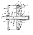
- the air brake cylinder according to Fig. 1 has a housing (1, 2, 3), which has a substantially cylindrical body part (1), a front wall (2) and a rear wall (3).
- a piston (4) which can be displaced longitudinally by the application of compressed air, is arranged, which is sealed relative to the housing part (1) by means of a circumferential seal (5).
- the piston (4) is rigidly connected to a piston rod (6).
- the piston rod (6) protrudes through an opening (15) of the housing (1, 2, 3), namely the opening (15) of the front wall (2).
- the piston rod (6) has an actuating surface which serves to actuate the application lever of a disc brake.
- the air brake cylinder with its front wall (2) by means of bolts (9) attached to the housing of a disc brake.
- the actuating surface comes with the brake lever of the disc brake to the plant.
- the bearing (13) advantageously also has a sealing function.
- the bearing (13) may advantageously be formed as a PUR ring.
- the piston (4) via a compressed air connection (12) can be acted upon with compressed air.
- compressed air is applied - the piston (4) moves against the force of a return spring (11) in the direction of the front wall (2).
- the front wall (2) has an opening (14) for pressure compensation, which is connected to the atmosphere or a compensation volume.
- the piston or a part rigidly connected to the piston is connected to an extension (7) on the side facing away from the opening (15).
- the extension (7) is guided axially in a bearing (10).
- the extension (7) is designed as an extension of the piston rod (6) penetrating the piston (4).
- the extension (7) is at least in certain operating states of the air brake cylinder, for Example in the in Fig. 1 shown unactuated state, in an extension region (8) of the housing (1, 2, 3) added.
- the extension area (8) in the embodiment according to Fig. 1 formed as part of the rear wall (3).
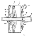
- the Fig. 2 shows the air brake cylinder according to Fig. 1 in the actuated state, that is, when the compressed air is applied to the piston (4) through the compressed air connection (12).
- the extension (7) is at least in certain operating states of the air brake cylinder in the extension area (8) added, for example, in the Fig. 1 apparent unactuated state of the air brake cylinder.
- the extension (7) has migrated substantially from the extension region (8), wherein the extension (7) is of course performed in all operating states of the air brake cylinder through the bearing (10).
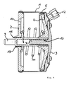
- the Fig. 3 shows an advantageous embodiment of the invention, in which the extension (7) is formed as part of the piston (4).
- the extension (7) can be advantageously connected as a separate part with the piston (4), for example by a threaded screw connection, or advantageously be formed integrally with the piston (4).
- the Fig. 4 shows a further advantageous embodiment of the air brake cylinder, wherein the extension (7) is rigidly connected to the rear wall (3) and projects into the interior of the piston rod (6).
- the bearing (10) is fixedly connected to the piston rod (6) and moves upon actuation of the piston (4) relative to the extension (7).
- this embodiment has the advantage of being particularly small-sized and in particular to claim little space on the back of the air brake cylinder.
- the bearings (10, 13) can be advantageously designed as an axial bearing.
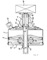
- the parking brake function advantageously has a unit for the mechanical locking of the piston (4) in its actuated position.
- the elements of the parking brake function have a locking element (16) provided with an external thread (20), a drive bolt (17) and a drive (18).
- the drive (18) is adapted to put the drive pin (17) in a rotational movement.
- the drive bolt (17) which has, for example, an external square profile, transmits the rotational movement to the locking element (16) which, as a result of the rotational movement, performs an axial movement with respect to the drive bolt (17).
- the axial movement is effected by the external thread (20) running in an internal thread (19) provided in the extension area (8).
- Fig. 6 is the embodiment of the air brake cylinder according to Fig. 5 shown, wherein the piston (4) is actuated by compressed air here.
- the parking brake function is shown in the illustration Fig. 6 not activated.
- Fig. 7 is the air brake cylinder according to Fig. 6 shown with operated parking brake function.
- the locking element (16) has been moved axially in the direction of the extension (7) as a result of an actuation of the drive (18) until the locking element (16) rests against the extension (7) and a return movement of the piston (4) therethrough prevented.
- an operation of the brake can be maintained without the compressed air operation of the piston (4) is required.
- the bearing (10) is arranged in an insert (21) for ease of assembly, which is mountable together with the bearing (10).
- the drive (18) may be formed, for example, as an electric motor with gear. Furthermore, those in the patent application DE 10 2005 001 234 A1 specified drives in the present air brake cylinder advantageously used.
Landscapes
- Engineering & Computer Science (AREA)
- General Engineering & Computer Science (AREA)
- Mechanical Engineering (AREA)
- Transportation (AREA)
- Braking Arrangements (AREA)
Applications Claiming Priority (1)
| Application Number | Priority Date | Filing Date | Title |
|---|---|---|---|
| DE200610056710 DE102006056710A1 (de) | 2006-11-30 | 2006-11-30 | Druckluftbremszylinder in Kolbenbauweise |
Publications (3)
| Publication Number | Publication Date |
|---|---|
| EP1927780A2 true EP1927780A2 (fr) | 2008-06-04 |
| EP1927780A3 EP1927780A3 (fr) | 2009-03-25 |
| EP1927780B1 EP1927780B1 (fr) | 2011-02-02 |
Family
ID=39110865
Family Applications (1)
| Application Number | Title | Priority Date | Filing Date |
|---|---|---|---|
| EP20070017822 Not-in-force EP1927780B1 (fr) | 2006-11-30 | 2007-09-12 | Cylindre à air comprimé avec arrangement de piston |
Country Status (2)
| Country | Link |
|---|---|
| EP (1) | EP1927780B1 (fr) |
| DE (2) | DE102006056710A1 (fr) |
Families Citing this family (2)
| Publication number | Priority date | Publication date | Assignee | Title |
|---|---|---|---|---|
| EP3765340A4 (fr) * | 2018-03-15 | 2021-12-01 | Haldex Brake Products Corporation | Système d'actionnement de frein à deux étages |
| GB2644064A (en) * | 2024-09-13 | 2026-03-18 | Meritor Heavy Vehicle Braking Systems Uk Ltd | Actuator for a heavy vehicle foundation brake |
Family Cites Families (2)
| Publication number | Priority date | Publication date | Assignee | Title |
|---|---|---|---|---|
| DE19815406A1 (de) * | 1998-04-06 | 1999-10-07 | Wabco Perrot Bremsen Gmbh | Bremsenzuspannvorrichtung |
| DE102005001234A1 (de) * | 2005-01-11 | 2006-07-20 | Wabco Gmbh & Co.Ohg | Bremszylinder mit Parkbremsfunktion |
-
2006
- 2006-11-30 DE DE200610056710 patent/DE102006056710A1/de not_active Ceased
-
2007
- 2007-09-12 DE DE200750006416 patent/DE502007006416D1/de active Active
- 2007-09-12 EP EP20070017822 patent/EP1927780B1/fr not_active Not-in-force
Also Published As
| Publication number | Publication date |
|---|---|
| EP1927780A3 (fr) | 2009-03-25 |
| DE102006056710A1 (de) | 2008-06-05 |
| EP1927780B1 (fr) | 2011-02-02 |
| DE502007006416D1 (de) | 2011-03-17 |
Similar Documents
| Publication | Publication Date | Title |
|---|---|---|
| EP0910754B1 (fr) | Ensemble actionneur pour frein de vehicule et frein de vehicule dote dudit ensemble actionneur | |
| EP0544851B1 (fr) | Dispositif de rattrapage de jeu commande par pression pour un frein de vehicule | |
| DE102010000882A1 (de) | Bremssystem von Typ "Brake-by-wire" | |
| DE102008062180A1 (de) | Kombinierte Fahrzeugbremse mit elektromechanisch betätigbarer Feststellbremse | |
| WO2012155884A1 (fr) | Dispositif de débrayage à actionnement hydraulique, comportant un carter composé de plusieurs pièces | |
| DE102008042778A1 (de) | Ansteuerbare elektromechanische Einrichtung zur Feststellung eines Kolbens in einem Zylinder und damit ausgestattete Fahrzeugbremsanlage | |
| WO2020216492A1 (fr) | Générateur de pression de freinage à commande électromécanique pour un système de freinage hydraulique d'un véhicule ainsi que véhicule comprenant un générateur de pression de freinage électromécanique | |
| EP1838974B1 (fr) | Cylindre de frein presentant une fonction de frein de stationnement | |
| DE102012103638A1 (de) | Fluidischer Fahrzeugtür-Schwenkantrieb | |
| EP1714048B1 (fr) | Frein de vehicule hydraulique | |
| DE10329694A1 (de) | Hydraulische Fahrzeugbremse | |
| EP1927780B1 (fr) | Cylindre à air comprimé avec arrangement de piston | |
| WO2008128613A1 (fr) | Cylindre combiné compact comportant un dispositif de relâchement manuel | |
| DE102007010765A1 (de) | Elektromechanischer Kupplungsaktuator | |
| DE102004062810A1 (de) | Hydraulische Fahrzeugbremse | |
| EP1841981B1 (fr) | Frein a disque | |
| DE102005010211B4 (de) | Parksperrenmechanismus für ein Kraftfahrzeug, welches ein Automatgetriebe oder ein automatisiertes Handschaltgetriebe umfasst | |
| DE102022000597A1 (de) | Parksperrenvorrichtung für eine Antriebsreinrichtung eines Fahrzeugs | |
| EP1778998B1 (fr) | Frein de vehicule a commande hydraulique a decompression | |
| DE102006005919B4 (de) | Kugelgewindetrieb | |
| EP2049374B1 (fr) | Unité d'actionnement de freins destinée à l'actionnement d'un système de freinage de véhicule à moteur | |
| DE102005023362B4 (de) | Fahrzeugbremse mit integrierter Feststelleinrichtung sowie Verfahren zum Betreiben einer Feststelleinrichtung | |
| DE102013217237A1 (de) | Kombinierte Fahrzeugbremse mit elektromechanischer Feststellbremsbetätigung | |
| DE102019101342A1 (de) | Verschleißnachsteller einer Kompakt-Bremszangeneinheit, und Kompakt-Bremszangeneinheit mit einem solchen Verschleißnachsteller | |
| DE19950657A1 (de) | Kupplungsbetätigungseinrichtung, insbesondere für Kraftfahrzeuge |
Legal Events
| Date | Code | Title | Description |
|---|---|---|---|
| PUAI | Public reference made under article 153(3) epc to a published international application that has entered the european phase |
Free format text: ORIGINAL CODE: 0009012 |
|
| AK | Designated contracting states |
Kind code of ref document: A2 Designated state(s): AT BE BG CH CY CZ DE DK EE ES FI FR GB GR HU IE IS IT LI LT LU LV MC MT NL PL PT RO SE SI SK TR |
|
| AX | Request for extension of the european patent |
Extension state: AL BA HR MK RS |
|
| PUAL | Search report despatched |
Free format text: ORIGINAL CODE: 0009013 |
|
| AK | Designated contracting states |
Kind code of ref document: A3 Designated state(s): AT BE BG CH CY CZ DE DK EE ES FI FR GB GR HU IE IS IT LI LT LU LV MC MT NL PL PT RO SE SI SK TR |
|
| AX | Request for extension of the european patent |
Extension state: AL BA HR MK RS |
|
| 17P | Request for examination filed |
Effective date: 20090925 |
|
| 17Q | First examination report despatched |
Effective date: 20091019 |
|
| AKX | Designation fees paid |
Designated state(s): DE FR GB SE |
|
| GRAP | Despatch of communication of intention to grant a patent |
Free format text: ORIGINAL CODE: EPIDOSNIGR1 |
|
| GRAS | Grant fee paid |
Free format text: ORIGINAL CODE: EPIDOSNIGR3 |
|
| GRAA | (expected) grant |
Free format text: ORIGINAL CODE: 0009210 |
|
| AK | Designated contracting states |
Kind code of ref document: B1 Designated state(s): DE FR GB SE |
|
| REG | Reference to a national code |
Ref country code: GB Ref legal event code: FG4D Free format text: NOT ENGLISH |
|
| REF | Corresponds to: |
Ref document number: 502007006416 Country of ref document: DE Date of ref document: 20110317 Kind code of ref document: P |
|
| REG | Reference to a national code |
Ref country code: DE Ref legal event code: R096 Ref document number: 502007006416 Country of ref document: DE Effective date: 20110317 |
|
| REG | Reference to a national code |
Ref country code: SE Ref legal event code: TRGR |
|
| PLBE | No opposition filed within time limit |
Free format text: ORIGINAL CODE: 0009261 |
|
| STAA | Information on the status of an ep patent application or granted ep patent |
Free format text: STATUS: NO OPPOSITION FILED WITHIN TIME LIMIT |
|
| 26N | No opposition filed |
Effective date: 20111103 |
|
| REG | Reference to a national code |
Ref country code: DE Ref legal event code: R097 Ref document number: 502007006416 Country of ref document: DE Effective date: 20111103 |
|
| REG | Reference to a national code |
Ref country code: DE Ref legal event code: R081 Ref document number: 502007006416 Country of ref document: DE Owner name: WABCO EUROPE BVBA, BE Free format text: FORMER OWNER: WABCO GMBH, 30453 HANNOVER, DE Effective date: 20121214 |
|
| REG | Reference to a national code |
Ref country code: FR Ref legal event code: TP Owner name: WABCO EUROPE BVBA, BE Effective date: 20130717 |
|
| REG | Reference to a national code |
Ref country code: GB Ref legal event code: 732E Free format text: REGISTERED BETWEEN 20131212 AND 20131218 |
|
| REG | Reference to a national code |
Ref country code: FR Ref legal event code: PLFP Year of fee payment: 9 |
|
| REG | Reference to a national code |
Ref country code: FR Ref legal event code: PLFP Year of fee payment: 10 |
|
| REG | Reference to a national code |
Ref country code: FR Ref legal event code: PLFP Year of fee payment: 11 |
|
| REG | Reference to a national code |
Ref country code: FR Ref legal event code: PLFP Year of fee payment: 12 |
|
| PGFP | Annual fee paid to national office [announced via postgrant information from national office to epo] |
Ref country code: SE Payment date: 20190924 Year of fee payment: 13 Ref country code: FR Payment date: 20190924 Year of fee payment: 13 |
|
| PGFP | Annual fee paid to national office [announced via postgrant information from national office to epo] |
Ref country code: GB Payment date: 20190924 Year of fee payment: 13 |
|
| PGFP | Annual fee paid to national office [announced via postgrant information from national office to epo] |
Ref country code: DE Payment date: 20190930 Year of fee payment: 13 |
|
| REG | Reference to a national code |
Ref country code: DE Ref legal event code: R119 Ref document number: 502007006416 Country of ref document: DE |
|
| GBPC | Gb: european patent ceased through non-payment of renewal fee |
Effective date: 20200912 |
|
| PG25 | Lapsed in a contracting state [announced via postgrant information from national office to epo] |
Ref country code: FR Free format text: LAPSE BECAUSE OF NON-PAYMENT OF DUE FEES Effective date: 20200930 Ref country code: DE Free format text: LAPSE BECAUSE OF NON-PAYMENT OF DUE FEES Effective date: 20210401 |
|
| PG25 | Lapsed in a contracting state [announced via postgrant information from national office to epo] |
Ref country code: SE Free format text: LAPSE BECAUSE OF NON-PAYMENT OF DUE FEES Effective date: 20200913 Ref country code: GB Free format text: LAPSE BECAUSE OF NON-PAYMENT OF DUE FEES Effective date: 20200912 |
|
| REG | Reference to a national code |
Ref country code: SE Ref legal event code: EUG |