EP1930512A2 - Dispositif de montage dans une conduite - Google Patents
Dispositif de montage dans une conduite Download PDFInfo
- Publication number
- EP1930512A2 EP1930512A2 EP07121182A EP07121182A EP1930512A2 EP 1930512 A2 EP1930512 A2 EP 1930512A2 EP 07121182 A EP07121182 A EP 07121182A EP 07121182 A EP07121182 A EP 07121182A EP 1930512 A2 EP1930512 A2 EP 1930512A2
- Authority
- EP
- European Patent Office
- Prior art keywords
- inspection shaft
- shaft
- connection
- inspection
- fluid
- Prior art date
- Legal status (The legal status is an assumption and is not a legal conclusion. Google has not performed a legal analysis and makes no representation as to the accuracy of the status listed.)
- Withdrawn
Links
Images

Classifications
-
- E—FIXED CONSTRUCTIONS
- E03—WATER SUPPLY; SEWERAGE
- E03F—SEWERS; CESSPOOLS
- E03F5/00—Sewerage structures
- E03F5/02—Manhole shafts or other inspection chambers; Snow-filling openings; accessories
-
- E—FIXED CONSTRUCTIONS
- E03—WATER SUPPLY; SEWERAGE
- E03F—SEWERS; CESSPOOLS
- E03F7/00—Other installations or implements for operating sewer systems, e.g. for preventing or indicating stoppage; Emptying cesspools
- E03F7/02—Shut-off devices
- E03F7/04—Valves for preventing return flow
-
- E—FIXED CONSTRUCTIONS
- E03—WATER SUPPLY; SEWERAGE
- E03F—SEWERS; CESSPOOLS
- E03F5/00—Sewerage structures
- E03F5/04—Gullies inlets, road sinks, floor drains with or without odour seals or sediment traps
- E03F2005/0412—Gullies inlets, road sinks, floor drains with or without odour seals or sediment traps with means for adjusting their position with respect to the surrounding surface
- E03F2005/0413—Gullies inlets, road sinks, floor drains with or without odour seals or sediment traps with means for adjusting their position with respect to the surrounding surface for height adjustment
Definitions
- the present invention relates to a device, in particular a cleaning tube, for installation in a pipeline under a floor slab, with a base body, in particular for receiving a backflow stop, comprising an inlet, a drain and a revision shaft, which is the base plate penetrating into these installable, in particular to the revision of the cleaning tube from the top.
- this cleaning tube has a main body which serves to receive or connect the backflow shutters, butterfly valves or additional inlets described above.
- the main body also has an inlet and a drain, which can be brought into fluid communication with the sewer line.
- a revision shaft is provided, which is installed in the bottom plate and extends from the base body on the underside of the bottom plate up to the top and thus allows access to the cleaning tube.
- a device which has a base body in which the inspection shaft acts as a drain pipe, so that For example, soil water is discharged from the top of the bottom plate on the inspection shaft into the body and fed from there via the drain of the sewer or pipeline.
- a device of the type mentioned above show, inter alia, the DE 39 36 752 C2 and the DE 10 2005 009 77 A1 , There, a cleaning pipe is described in each case, which has a base on an inlet and a drain through which the cleaning pipe is installed in a pipeline.
- the main body has a revision shaft which is accessible from an upper side of a base plate and over which, for example, a backflow closure or a similar blocking flap can be inserted into the base body.
- the present invention does not necessarily relate only to a cleaning tube and a pipeline which is arranged completely below the base plate. Rather, here also cleaning pipes and pipes are affected, which are arranged within the bottom plate, but they protrude with a, albeit small part, from the bottom of the same, thus allowing the ingress of soil water.
- the present invention is therefore based on the object, a device and in particular a cleaning pipe for installation in a pipeline under a floor slab of the aforementioned type such that it is more versatile while being easier to install and also functionally reliable.
- this object is achieved by a device, in particular a cleaning tube, for installation in a pipeline under a bottom plate, with a base body, in particular for receiving a backflow stop, comprising an inlet, a drain and a revision shaft, which penetrates the base plate penetrating into this is, in particular for the revision of the cleaning tube from the top, wherein the inspection shaft on its outer wall at different positions along the shaft axis has a plurality of preferably circumferential sealing seats and at least one circumferential sealing collar, which is in particular releasably held in such a seal seat, for substantially fluid-tight Connection of the inspection shaft to the base plate.
- Under floor plate here are all structural panels and in particular plates of a cast material, such as concrete understood that an access level, here eg an upper side of the bottom plate, from a pipeline level, here eg the underside of the bottom plate separate, wherein in the pipeline level a pipeline is performed, whose revision or access from the access level is necessary.
- a pipeline level here eg the underside of the bottom plate separate
- such plates are affected in which a penetration of water, soil moisture or other fluid from one side to the other should be prevented.
- Under seal seat here are all recordings and mounting elements to understand, which are formed on the inspection shaft and serve to receive a sealing collar. Preferably, however, the sealing seats are integrally formed with the inspection shaft.
- sealing collar here are all sealing elements to understand that can be added in particular fluid-tight in the seal seat on the inspection shaft and at the same time installed sealingly on the bottom plate or poured into it.
- the device according to the invention can be connected not only simultaneously with the construction of a base plate but also subsequently to corresponding recesses in the finished base plate.
- the sealing collar is here in particular releasably designed, so that it can also be used shortly before mounting in the respectively required seal seat on the inspection shaft. In this regard, but it is also possible the sealing collar in addition to glue in the seal seat or similarly seal on the inspection shaft, if necessary.
- the sealing collar on the outer wall of the inspection shaft can be used in the manufacture of the base plate, e.g. be poured, so that a substantially fluid-tight connection of the inspection shaft is ensured to the bottom plate and the penetration of soil water is prevented from the bottom of the bottom plate to the top.
- this fluid-tight connection also prevents the penetration of surface water from the top of the bottom plate to the bottom, so that the device of the invention can of course find their use for a floor drain, which is to be connected to a pipe under a floor plate.
- a single inspection shaft at least as far as the sealing between the inspection shaft and base plate, can also be used with different base plate thicknesses by merely repositioning the sealing collar into other sealing seats or inserting additional sealing collars into still free sealing seats.
- this can be cut to length, for example by means of appropriate tools or run as a variable-length inspection shaft.
- the sealing seats are at least partially formed from a uniform sequence of mutually parallel, each forming a receiving space, preferably circumferential clamping projections.
- This allows the very cost-effective design of the sealing seats on the outer wall of the inspection shaft, as always a clamping projection is used to form two adjacent sealing seats.
- a clamping projection is used to form two adjacent sealing seats.
- the execution of the clamping projections and the receiving intermediate spaces formed by these is based on the prior art and the devices known there for the formation of particular fluid-tight sealing seats directed. So here, for example, the formation of the clamping projections with corresponding undercuts is conceivable to guarantee a secure and fluid-tight fit of the sealing collar on the clamping projection or in the receiving space.
- seal seat corresponding additional sealing elements, such as clamping rails, which additionally press or seal the sealing collar on the inspection shaft.
- additional sealing elements such as clamping rails
- the formation of only one seal seat is possible, which is then formed by two mutually parallel, forming a receiving space, preferably circumferential clamping projections.
- the inspection shaft has a revision shaft receptacle on the base body and at least one inspection shaft element, which can be connected to one another in a detachable and / or fluid-tight manner via a shaft connection element.
- a revision shaft receptacle on the base body and at least one inspection shaft element, which can be connected to one another in a detachable and / or fluid-tight manner via a shaft connection element.
- the inspection shaft element can also be connected in a detachable and / or fluid-tight manner to a further inspection shaft element via a further shaft connecting element.
- a further inspection shaft element via a further shaft connecting element.
- the shaft connecting element for connecting the inspection shaft receptacle and the inspection shaft element or two inspection shaft elements preferably has a connection extension on an element and a connection extension receptacle on the other element, which can be brought together in a particular releasable latching connection.
- the fluid-tight connection of the individual components to one another guarantees that no water enters the inspection shaft from the outside or that no water which flows off, for example, via the inspection shaft used as a downcomer penetrates to the outside.
- the use of the known from the prior art fluid-tight connection elements that is, for example, the arrangement of corresponding sealing elements within the manhole connecting element possible.
- each inspection shaft element and / or the inspection shaft receiving at least each have a clamping projection which forms a common receiving space and thus a common sealing seat with a clamping projection of a further inspection shaft element.
- the arrangement of a sealing collar is also possible at the connection points between the inspection shaft element and the inspection shaft receptacle or a further inspection shaft element.
- At least one seal seat is formed on an outer wall of the inspection shaft receptacle.
- the cleaning tube in a fluid-tight manner on the bottom plate even without connected revision shaft elements. So it is sometimes necessary to form in the bottom plate a pump sump or a similar inspection space, which in turn has a recess into which the Base body or the inspection shaft receptacle of the cleaning tube protrudes fluid-tight. Due to the design of the seal seat on the inspection shaft receiving the inspection shaft receiving fluid-tight can now be connected to the pump sump, etc., without the use of a revision shaft element is necessary.
- the inspection shaft has an attachment element for substantially flush installation in the upper side of the base plate, which stands with a connecting piece with the inspection shaft in a particular fluid-tight sliding connection.
- the attachment element usually serves to receive a cover, which can be positioned in particular in a fluid-tight manner in the attachment element.
- a connecting piece on the attachment element which is in a particular fluid-tight sliding connection with the inspection shaft, a height adjustment between the inspection shaft and the surface of the bottom plate is very easily possible.
- the attachment element can be easily placed on the top of the base plate, wherein the connection piece then slides into the inspection shaft. If, for example, an insulating layer or a further floor structure is provided on the base plate, the attachment element can be further pulled out of the inspection shaft and then still be in fluid-tight connection with the revision shaft, which is usually already cast in this construction state.
- a blind cover such that it can be placed on the inspection shaft during the production of the base plate in order to seal it in a fluid-tight manner during construction.
- a manhole connection element can be made of the above-mentioned manhole connection element.
- connection piece has along its extension axis at least one preferably circumferential cut-off marking and in particular a cut-off marking designed as a predetermined breaking point.
- a coarse length adjustment of the connecting piece to different strength floor panels is possible.
- Fig. 1 shows an isometric view of a first embodiment of the device according to the invention. It is a cleaning pipe 1, which in a below a bottom plate 30 (see Fig. 2 ) running pipeline 36 can be installed.
- the cleaning pipe 1 on a base body 2, which is provided with an inlet 4 and a drain 6, which are brought into fluid communication with the pipe 36.
- the main body 2 also includes a revision shaft 10, which is shed for example when concreting the bottom plate 30 with this.
- the inspection shaft 10 includes a revision shaft receptacle 12, which is formed here in one piece with the main body 2 of the cleaning tube 1.
- a revision shaft receptacle 12 which is formed here in one piece with the main body 2 of the cleaning tube 1.
- the inspection shaft 10 or the individual inspection shaft elements 18 has a plurality of sealing seats 14 along its shaft axis A SCH on, which serve to receive a sealing collar 16.
- the sealing seats 14 are at least partially formed from a uniform sequence of mutually parallel, each one receiving space 15 forming clamping projections 17.
- the sealing seats 14 are here formed the inspection shaft 10 circumferentially, so that a completely fluid-tight connection of the sealing collar 16 to the inspection shaft 10 is possible.
- FIG. 2 is that in Fig. 1 shown cleaning tube 1 shown in a side view and in the assembled state. Shown is the pipe 36 which is connected to the inlet 4 and the outlet 6 of the cleaning tube 1.
- the pipeline 36 and the cleaning pipe 1 are, as known from the prior art, mounted on a sand bed, which also serves as a foundation for the bottom plate 30. Also shown is the bottom plate 30, which is molded onto the inspection shaft 10.
- the inspection shaft 10 has the inspection shaft receptacle 12 on the main body 2 of the cleaning tube 1 and in this embodiment, two inspection shaft elements 18, 18 '. Completed at its top of the inspection shaft 1 through the attachment element 20, which is here installed substantially flush with the top 32 of the concrete slab 30.
- the inspection shaft 10 has the plurality of sealing seats 14, into which two sealing collars 16 are inserted.
- the sealing seats 14 are at least partially formed from a uniform sequence of mutually parallel associated, each forming a receiving space 15, in this case the inspection shaft 10 encircling clamping projections 17.
- the recording spaces 15 shown here are; 15 'is formed by three parallel clamping projections 17, 17' and 17 ", thus acting as the central clamping projection 17 'as a common clamping projection for the two resulting sealing seats 14, 14'.
- a seal seat 14 "over the clamping projection 17" and a corresponding folds 21 of a manhole connecting element 19 is formed.
- a seal seat is also arranged in this embodiment on the inspection shaft receptacle 12, which also can receive a sealing collar.
- the inspection shaft receptacle 12, the inspection shaft elements 18 and the attachment element 20 are connected to one another in this embodiment in each case via a shaft connecting element 19.
- the execution of this manhole connection elements 19 is explicitly in the 3 and 4 and will be discussed in detail below.
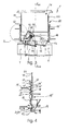
- Fig. 3 shows a second embodiment of the cleaning tube 1 according to the invention, wherein in Fig. 4 the in Fig. 3 marked section IV is shown in detail.
- a base body 2 is provided, which via an inlet 4 and a drain 6 to a pipe (not shown) can be connected.
- the main body 2 further comprises a revision shaft 10, which allows access to the main body 2 from an upper side of a bottom plate (not shown).
- the inspection shaft 10 is also in this embodiment, a multi-part inspection shaft 10, consisting of a inspection shaft receiving 12, two inspection shaft elements 18, 18 'and an attachment element 20th
- the attachment element 20 is not here, as in the previously discussed first embodiment via a connecting element 19 connected to the inspection shaft 18, but has a connecting piece 22 which is in sliding contact with the inspection shaft element 18 '. In this way, a stepless height adjustment of the inspection shaft 10 is ensured within a certain range by the connecting piece 22 of the attachment element 20 can be pushed into the inspection shaft element 18 'and pulled out of this.
- the connecting piece 22 has a plurality of AblShmark isten 26, which allow for example by means of a saw the exact cutting to length of the connecting piece 22.
- the inspection shaft element 18' has a receptacle 37 for receiving a sealing element 27, which rests substantially fluid-tight on the connecting piece 22.
- a shaft connecting element 19 is provided.
- the inspection shaft receptacle 12 has a connection extension receptacle 28 and the inspection shaft element 18 has a connection extension 29 that is designed to be complementary to one another, that they function as a shaft connection element 19 and can be brought together in a latching connection.
- the inspection shaft element 18 and the inspection shaft element 18 'and also in the Fig. 1 and 2 shown attachment element 20 connected to each other.
- each connection extension 29 has a latching nose 31 which engages in a corresponding undercut 33 on the connection extension receptacle 28.
- the main body 20 has, as in Fig. 3
- a backflow stopper 40 which serves to shut off the pipe 36 in the gearstaufall.
- the backflow lock 40 has two flaps 44, 46, wherein one flap is an engine flap 44 and the other flap 46 is a manually controlled flap 46.
- the manually controlled flap allows the determination in three different positions, a closed position, an open position and a pendulum position, wherein in the pendulum position, the free mobility of the flap 46 is ensured between the open position and the closed position.
- the engine flap 44 is operated via a motor 42, which is connected via a spindle drive 48 with the engine door 44 in operative connection.
- the motor 42 is arranged substantially perpendicular to a central position of the flap 44. This middle position results from a half angle between the open position and the closed position.
Landscapes
- Health & Medical Sciences (AREA)
- Life Sciences & Earth Sciences (AREA)
- Engineering & Computer Science (AREA)
- Hydrology & Water Resources (AREA)
- Public Health (AREA)
- Water Supply & Treatment (AREA)
- Sewage (AREA)
- Cleaning In General (AREA)
- Quick-Acting Or Multi-Walled Pipe Joints (AREA)
- Pipe Accessories (AREA)
Applications Claiming Priority (1)
| Application Number | Priority Date | Filing Date | Title |
|---|---|---|---|
| DE102006056146.5A DE102006056146B4 (de) | 2006-11-28 | 2006-11-28 | Reinigungsrohr zum Einbau in eine Rohrleitung unter einer Bodenplatte |
Publications (2)
| Publication Number | Publication Date |
|---|---|
| EP1930512A2 true EP1930512A2 (fr) | 2008-06-11 |
| EP1930512A3 EP1930512A3 (fr) | 2010-03-10 |
Family
ID=38984513
Family Applications (1)
| Application Number | Title | Priority Date | Filing Date |
|---|---|---|---|
| EP07121182A Withdrawn EP1930512A3 (fr) | 2006-11-28 | 2007-11-21 | Dispositif de montage dans une conduite |
Country Status (2)
| Country | Link |
|---|---|
| EP (1) | EP1930512A3 (fr) |
| DE (1) | DE102006056146B4 (fr) |
Families Citing this family (1)
| Publication number | Priority date | Publication date | Assignee | Title |
|---|---|---|---|---|
| DE102018109220A1 (de) * | 2018-04-18 | 2019-10-24 | Meierguss Sales & Logistics Gmbh & Co. Kg | Schachtabdeckungsrahmen, Schachtabdeckungsanordnung, Schachtanordnung und Installationsverfahren |
Family Cites Families (7)
| Publication number | Priority date | Publication date | Assignee | Title |
|---|---|---|---|---|
| GB2093096B (en) * | 1981-02-14 | 1985-07-03 | Battye Philip Gerald | Terminal drainage fittings |
| DE8306772U1 (de) * | 1983-03-09 | 1983-09-29 | Passavant-Werke AG & Co KG, 6209 Aarbergen | Reinigungsverschluss fuer abwasserleitungen |
| DE3936752C2 (de) * | 1989-11-04 | 1995-08-10 | Bernhard Kessel | Abwasserrohr mit Reinigungsöffnung |
| DE10050090A1 (de) * | 2000-10-10 | 2002-05-08 | Betonol Planung Von Sperrbeton | Abdichtungsflansch und Verfahren zur Verwendung desselben |
| DE20304678U1 (de) * | 2003-03-21 | 2004-09-23 | Viega Gmbh & Co. Kg | Ablauf mit einem Rückstauverschluss |
| DE102005013942A1 (de) * | 2004-12-23 | 2006-07-06 | Dallmer Gmbh & Co. Kg | Ablaufvorrichtung für die Anordnung an einer Bodenplatte mit einer Öffnung für Abwasser sowie Anordnung einer derartigen Ablaufvorrichtung an einer Bodenplatte |
| DE102005009777B4 (de) * | 2005-01-05 | 2008-08-21 | Aco Severin Ahlmann Gmbh & Co. Kg | Rückstauverschluss |
-
2006
- 2006-11-28 DE DE102006056146.5A patent/DE102006056146B4/de active Active
-
2007
- 2007-11-21 EP EP07121182A patent/EP1930512A3/fr not_active Withdrawn
Also Published As
| Publication number | Publication date |
|---|---|
| EP1930512A3 (fr) | 2010-03-10 |
| DE102006056146B4 (de) | 2021-04-01 |
| DE102006056146A1 (de) | 2008-06-05 |
Similar Documents
| Publication | Publication Date | Title |
|---|---|---|
| DE102011051430B4 (de) | Abwasserablauf mit Geruchsverschluss | |
| DE102011116874A1 (de) | Schacht | |
| DE102012001610B4 (de) | Rohreinbausatz | |
| EP3680406B1 (fr) | Dispositif de drainage pour l'installation dans le sol d'une salle | |
| EP1930512A2 (fr) | Dispositif de montage dans une conduite | |
| EP1679407A1 (fr) | Fermeture anti-refoulement | |
| EP1863978B1 (fr) | Corps de rigole | |
| DE202011051047U1 (de) | Ablaufanordnung | |
| DE102023135533A1 (de) | Flexibel justierbares Ablaufsystem für einen Duschplatz | |
| EP3064650B1 (fr) | Système de fermeture de puits et procédé de montage | |
| DE102007030875B4 (de) | Formbauteil aus Beton und Verfahren zur Herstellung eines solchen Formbauteils | |
| DE9403517U1 (de) | Kanalisations-Schachtunterteil | |
| DE10320995A1 (de) | Stoßfugenanordnung bei einem Bauwerkteil, Betonfertigteile hierfür und Bauwerkteil mit solchen Betonfertigteilen und Stoßfugenanordnungen | |
| DE102008032513A1 (de) | Entwässerungsrinne | |
| DE8220949U1 (de) | Rinnenelement fuer eine entwaesserungsrinne | |
| DE102013207951A1 (de) | Entwässerungssystem für eine Verkehrsfläche | |
| EP3420149B1 (fr) | Élément de raccordement entre une canalisation et une bouche d'égout | |
| DE202009015672U1 (de) | Duschtassenelement | |
| DE10101613C2 (de) | Adapterelement zur Verbindung einer Schibevorrichtung mit einer Einlauföffnung eines Sammelbeckens und Fertigsammelbecken | |
| WO2005012661A1 (fr) | Dispositif d'ecoulement des eaux de ruissellement | |
| AT524807A2 (de) | Balkon- oder Terrassenelement mit einer Entwässerungseinrichtung, Entwässerungseinrichtung für ein solches Balkon- oder Terrassenelement sowie Herstellungsverfahren | |
| DE20318617U1 (de) | Einlaufgehäuse | |
| EP2789736B1 (fr) | Système de drainage d'un rail | |
| DE29712421U1 (de) | Absturzschacht | |
| DE29500559U1 (de) | Im Erdreich einbaubarer Schacht |
Legal Events
| Date | Code | Title | Description |
|---|---|---|---|
| PUAI | Public reference made under article 153(3) epc to a published international application that has entered the european phase |
Free format text: ORIGINAL CODE: 0009012 |
|
| AK | Designated contracting states |
Kind code of ref document: A2 Designated state(s): AT BE BG CH CY CZ DE DK EE ES FI FR GB GR HU IE IS IT LI LT LU LV MC MT NL PL PT RO SE SI SK TR |
|
| AX | Request for extension of the european patent |
Extension state: AL BA HR MK RS |
|
| PUAL | Search report despatched |
Free format text: ORIGINAL CODE: 0009013 |
|
| AK | Designated contracting states |
Kind code of ref document: A3 Designated state(s): AT BE BG CH CY CZ DE DK EE ES FI FR GB GR HU IE IS IT LI LT LU LV MC MT NL PL PT RO SE SI SK TR |
|
| AX | Request for extension of the european patent |
Extension state: AL BA HR MK RS |
|
| RIC1 | Information provided on ipc code assigned before grant |
Ipc: E03F 5/04 20060101ALI20100201BHEP Ipc: E03F 5/02 20060101AFI20100201BHEP |
|
| AKY | No designation fees paid | ||
| STAA | Information on the status of an ep patent application or granted ep patent |
Free format text: STATUS: THE APPLICATION IS DEEMED TO BE WITHDRAWN |
|
| 18D | Application deemed to be withdrawn |
Effective date: 20100911 |
|
| REG | Reference to a national code |
Ref country code: DE Ref legal event code: R108 Effective date: 20110222 Ref country code: DE Ref legal event code: 8566 |