EP1930636A2 - Bidirektionales Über-/Unterdruckventil - Google Patents
Bidirektionales Über-/Unterdruckventil Download PDFInfo
- Publication number
- EP1930636A2 EP1930636A2 EP20070122192 EP07122192A EP1930636A2 EP 1930636 A2 EP1930636 A2 EP 1930636A2 EP 20070122192 EP20070122192 EP 20070122192 EP 07122192 A EP07122192 A EP 07122192A EP 1930636 A2 EP1930636 A2 EP 1930636A2
- Authority
- EP
- European Patent Office
- Prior art keywords
- valve
- flow
- valve element
- closed position
- housing
- Prior art date
- Legal status (The legal status is an assumption and is not a legal conclusion. Google has not performed a legal analysis and makes no representation as to the accuracy of the status listed.)
- Withdrawn
Links
- 239000012530 fluid Substances 0.000 claims description 18
- 230000002093 peripheral effect Effects 0.000 claims description 4
- 230000002457 bidirectional effect Effects 0.000 abstract description 12
- 239000002828 fuel tank Substances 0.000 description 10
- IJGRMHOSHXDMSA-UHFFFAOYSA-N Atomic nitrogen Chemical compound N#N IJGRMHOSHXDMSA-UHFFFAOYSA-N 0.000 description 5
- 238000004088 simulation Methods 0.000 description 5
- 239000000446 fuel Substances 0.000 description 3
- 230000007423 decrease Effects 0.000 description 2
- 239000011261 inert gas Substances 0.000 description 2
- 229910052757 nitrogen Inorganic materials 0.000 description 2
- 230000003534 oscillatory effect Effects 0.000 description 2
- 229910001873 dinitrogen Inorganic materials 0.000 description 1
- 230000000694 effects Effects 0.000 description 1
- 239000007789 gas Substances 0.000 description 1
- 238000000034 method Methods 0.000 description 1
- 238000013022 venting Methods 0.000 description 1
Images


Classifications
-
- F—MECHANICAL ENGINEERING; LIGHTING; HEATING; WEAPONS; BLASTING
- F16—ENGINEERING ELEMENTS AND UNITS; GENERAL MEASURES FOR PRODUCING AND MAINTAINING EFFECTIVE FUNCTIONING OF MACHINES OR INSTALLATIONS; THERMAL INSULATION IN GENERAL
- F16K—VALVES; TAPS; COCKS; ACTUATING-FLOATS; DEVICES FOR VENTING OR AERATING
- F16K17/00—Safety valves; Equalising valves, e.g. pressure relief valves
- F16K17/18—Safety valves; Equalising valves, e.g. pressure relief valves opening on surplus pressure on either side
- F16K17/19—Equalising valves predominantly for tanks
- F16K17/196—Equalising valves predominantly for tanks spring-loaded
-
- Y—GENERAL TAGGING OF NEW TECHNOLOGICAL DEVELOPMENTS; GENERAL TAGGING OF CROSS-SECTIONAL TECHNOLOGIES SPANNING OVER SEVERAL SECTIONS OF THE IPC; TECHNICAL SUBJECTS COVERED BY FORMER USPC CROSS-REFERENCE ART COLLECTIONS [XRACs] AND DIGESTS
- Y10—TECHNICAL SUBJECTS COVERED BY FORMER USPC
- Y10T—TECHNICAL SUBJECTS COVERED BY FORMER US CLASSIFICATION
- Y10T137/00—Fluid handling
- Y10T137/7722—Line condition change responsive valves
- Y10T137/7771—Bi-directional flow valves
- Y10T137/7772—One head and seat carried by head of another
- Y10T137/7777—Both valves spring biased
Definitions
- the present invention generally relates to bi-directional pressure relief valves and, more particularly, to a bi-directional pressure relief valve that exhibits improved controllability and improved valve stability.
- Many systems include one or more pressure responsive valves to control and/or maintain one or more pressures within prescribed limits.
- a fuel tank inerting system typically operates by displacing atmospheric air in the fuel tank ullage with an inert gas, such as nitrogen enriched air (NEA).
- the fuel tank inerting system may additionally include one or more valves to maintain the inert atmosphere in the fuel tanks by not unnecessarily allowing the inert gas to escape from, and preventing the atmospheric air from flowing into, the tanks.
- the valve (or valves) may also be configured to control the differential pressure between the surrounding atmosphere and the fuel tank internal volume to within a specified range.
- the valve that is used to control fuel tank-to-atmosphere differential pressure may be implemented as a bi-directional, positive and negative pressure relief valve. With such valves, if pressure within the associated fuel tank (or tanks) increases such that the fuel tank-to-atmosphere differential pressure exceeds a predetermined positive value, the valve opens in a direction that lowers tank internal pressure. Conversely, if pressure within the associated fuel tank (or tanks) decreases such that the fuel tank-to-atmosphere differential pressure falls below a predetermined negative value, the valve opens in a direction that increases tank internal pressure toward atmospheric pressure.
- bi-directional positive and negative pressure relief valves are generally safe and reliable, these valves can suffer certain drawbacks. For example, many of these valves are fairly large, heavy, and/or bulky, and may thus not fit within some constricted space envelopes. Many of these valves also do not exhibit relatively high pressure control and flow accuracies, and may also exhibit less than optimal stability. As a result, these valves may exhibit greater than desirable oscillatory motion during certain aircraft altitude changes.
- a bi-directional positive and negative pressure relief valve includes a housing, a first valve element, a second valve element, a first spring element, and a second spring element.
- the housing includes a first valve seat, a first flow port, a second flow port, and an inner surface that defines a first flow passage between the first and second flow ports.
- the first valve element is mounted at least partially within the housing and is movable between a closed position and a plurality of open positions. In the closed position the first valve element engages the first valve seat and at least substantially prevents flow between the first and second flow ports. In the open positions the first valve element is spaced apart from the first valve seat and allows flow between the first and second flow ports.
- the first valve element defines a second valve seat and includes one or more flow openings that extend therethrough, and an outer peripheral surface spaced apart from the housing inner surface that defines a first restriction flow area therebetween.
- the second valve element is mounted at least partially within the housing and is movable between a closed position and a plurality of open positions. In the closed position the second valve element engages the second valve seat and at least substantially prevents flow through the one or more flow openings. In the open positions the second valve element is spaced apart from the second valve seat and allows flow through the one or more flow openings.
- the first spring element is disposed within the housing and is configured to supply a first bias force to the first valve element that urges the first valve element toward its closed position and maintains the first valve element in its closed position unless a differential fluid pressure between the first flow port and the second flow port exceeds a first predetermined differential pressure magnitude.
- the second spring element is disposed within the housing and is configured to supply a second bias force to the second valve element that urges the second valve element toward its closed position and maintains the second valve element in its closed position unless a differential fluid pressure between the first flow passage and the second flow passage exceeds a second predetermined differential pressure magnitude.
- the first valve element and at least a portion of the first flow passage are dimensioned such that the first restriction flow area varies as the first valve element moves between its closed position and at least one of its plurality of open positions.
- a bi-directional positive and negative pressure relief valve in another exemplary embodiment, includes a housing, a first valve element, a second valve element, a first spring element, a second spring element, and a pneumatic damper.
- the housing includes a first valve seat, a first flow port, a second flow port, and an inner surface that defines a first flow passage between the first and second flow ports.
- the first valve element is mounted at least partially within the housing and is movable between a closed position and a plurality of open positions. In the closed position the first valve element engages the first valve seat and at least substantially prevents flow between the first and second flow ports. In the open positions the first valve element is spaced apart from the first valve seat and allows flow between the first and second flow ports.
- the first valve element additionally defines a second valve seat and includes one or more flow openings that extend therethrough.
- the second valve element is mounted at least partially within the housing and is movable between a closed position and a plurality of open positions. In the closed position the second valve element at least substantially prevents flow through the one or more flow openings. In the open positions flow through the one or more flow openings is allowed.
- the first spring element is disposed within the housing and is configured to supply a first bias force to the first valve element that urges the first valve element toward its closed position and maintains the first valve element in its closed position unless a differential fluid pressure between the first flow port and the second flow port exceeds a first predetermined differential pressure magnitude.
- the second spring element is disposed within the housing and is configured to supply a second bias force to the second valve element that urges the second valve element toward its closed position and maintains the second valve element in its closed position unless a differential fluid pressure between the second flow port and the first flow port exceeds a second predetermined differential pressure magnitude.
- the pneumatic damper coupled to the second valve element.
- a bi-directional positive and negative pressure relief valve in yet another exemplary embodiment, includes a housing, a first valve element, a second valve element, a first spring element, a second spring element, and a pneumatic damper.
- the housing includes a first valve seat, a first flow port, a second flow port, and an inner surface that defines a first flow passage between the first and second flow ports.
- the first valve element is mounted at least partially within the housing and is movable between a closed position and a plurality of open positions. In the closed position the first valve element engages the first valve seat and at least substantially prevents flow between the first and second flow ports. In the open positions the first valve element is spaced apart from the first valve seat and allows flow between the first and second flow ports.
- the first valve element defines a second valve seat and includes one or more flow openings that extend therethrough, and an outer peripheral surface spaced apart from the housing inner surface that defines a first restriction flow area therebetween.
- the second valve element is mounted at least partially within the housing and is movable between a closed position and a plurality of open positions. In the closed position the second valve element engages the second valve seat and at least substantially prevents flow through the one or more flow openings. In the open positions the second valve element is spaced apart from the second valve seat and allows flow through the one or more flow openings.
- the first spring element is disposed within the housing and is configured to supply a first bias force to the first valve element that urges the first valve element toward its closed position and maintains the first valve element in its closed position unless a differential fluid pressure between the first flow port and the second flow port exceeds a first predetermined differential pressure magnitude.
- the second spring element is disposed within the housing and is configured to supply a second bias force to the second valve element that urges the second valve element toward its closed position and maintains the second valve element in its closed position unless a differential fluid pressure between the first flow passage and the second flow passage exceeds a second predetermined differential pressure magnitude.
- the pneumatic damper coupled to the second valve element.
- the first valve element and at least a portion of the first flow passage are dimensioned such that the first restriction flow area varies as the first valve element moves between its closed position and at least one of its plurality of open positions.
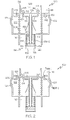
- FIG. 1 is a schematic representation of one embodiment of a bidirectional positive/negative pressure relief valve
- FIGS. 2 and 3 depict the schematically represented bidirectional positive/negative pressure relief valve of FIG. 1 in first and second pressure relief directions, respectively;
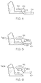
- FIGS. 4-6 are close-up views of a portion of the valve of FIG. 1 with one of the valve elements in various valve positions;
- FIG. 7 is a plan view of an exemplary physical implementation of the bidirectional positive/negative pressure relief valve of FIG. 1 ;
- FIG. 8 is a cross section view of the bidirectional positive/negative pressure relief valve depicted in, and taken along line 8-8 of FIG. 7 ;
- FIG. 9 is a graph that depicts simulation results for tank having a valve configured such that its valve elements snap open at predetermined differential pressures during an aircraft climb at 6000 feet per minute;
- FIG. 10 is a graph that depicts simulation results for tank having a valve configured in accordance with embodiments of the present invention during an aircraft climb at 6000 feet per minute.
- FIG. 1 A schematic representation of one embodiment of a bidirectional positive/negative pressure relief valve 100 is depicted in FIG. 1 , and includes a housing 102, a first valve element 104, a second valve element 106, a first spring element 108, a second spring element 112, and a pneumatic damper 114.
- the housing 102 includes a first flow port 116, a second flow port 118, and an inner surface 121 that defines a first flow passage 122 between the flow ports 116, 118.
- the valve 100 is preferably configured to be mounted in a manner that the first flow port 116 is in fluid communication with a first environment 124, and the second flow port 118 is in fluid communication with a second environment 126.
- the fist and second environments 124, 126 may vary, but in the depicted embodiment the first environment 124 is an aircraft fuel tank ullage, and the second environment is an ambient environment outside of the fuel tank. As FIG. 1 additionally depicts, the housing 102 further defines a first valve seat 128.
- the first valve element 104 is preferably mounted within, or at least partially within, the housing 102 and is movable between a closed position, which is the position depicted in FIG. 1 , and a plurality of open positions, one of which is the depicted in FIG. 2 .
- the first valve element 104 defines a second valve seat 132, and that one or more flow openings 134 extend through the first valve element 104.
- the first valve element 104 includes a conduit 136, an annular section 138, and a skirt 142.
- the conduit 136 extends axially from the first valve element 104 and includes an inner surface 143 that defines a second flow passage 144.
- the annular section 138 also extends axially from the first valve element 104, but into the first flow passage 122.
- the skirt 142 extends radially from the annular section 138 toward the housing inner surface 121.
- the second valve element 106 is also preferably mounted within, or at least partially within, the housing 102 and is movable between a closed position, which is the position depicted in FIG. 1 , and a plurality of open positions, one of which is the depicted in FIG. 3 .
- the second valve element 106 includes an annular section 146 and a skirt 148.
- the second valve element annular section 146 extends axially from the second valve element 106 into the second flow passage 144, and the second valve element skirt 148 extends radially from the second valve element annular section 146 toward the conduit inner surface 143.
- the second valve element 106 When the second valve element 106 is in its closed position, it engages the second valve seat 132 and prevents, or at least substantially prevents, flow through the one or more flow openings 134. Conversely, and with reference now to FIG. 3 , when the second valve element 106 is in an open position, it no longer engages the second valve seat 132. As a result, flow may occur through the one or more flow openings 134, via the second flow passage 144.
- the first and second valve elements 104, 106 are maintained in the respective closed positions as a result of bias forces supplied thereto by the first and second spring elements 108, 112, respectively.
- the first spring element 108 is disposed within the housing 102 and is configured to supply a first bias force to the first valve element 104.
- the first bias force urges the first valve element 104 toward its closed position.
- the first spring element 108 is configured such that the first bias force supplied thereby maintains the first valve element 104 in its closed position unless a differential fluid pressure between the first flow port 116 and the second flow port 118 exceeds a first predetermined differential pressure magnitude.
- first valve element 104 will begin opening when the fluid pressure at the second flow port 118 exceeds the fluid pressure at the first flow port 116 by the first predetermined differential pressure magnitude. It will be appreciated that the value of the first differential pressure magnitude may vary, and may be selected to meet, for example, desired system and/or component specifications.
- the second spring element 112 is also disposed within the housing 102 and is configured to supply a second bias force to the second valve element 106.
- the second bias force similar to the effect of the first bias force on the first valve element 104, urges the second valve element 106 toward its closed position.
- the second spring element 112 is similarly configured such that the second bias force supplied thereby maintains the second valve element 106 in its closed position unless a differential fluid pressure between the first flow port 116 and the second flow port 118 exceeds a second predetermined differential pressure magnitude.
- the second valve element 106 will begin opening when the fluid pressure at the first flow port 116 exceeds the fluid pressure at the second flow port 118 by the second predetermined differential pressure magnitude.
- the value of the second differential pressure magnitude may vary, and may be selected to meet, for example, desired system and/or component specifications.
- the pneumatic damper 114 is disposed at least partially within the housing 102, and is coupled to both the first valve element 104 and the second valve element 106.
- the pneumatic damper 114 because it is coupled to both valve elements 104, 106, dampens the motion of either valve element 104, 106.
- the pneumatic damper 114 could be implemented using any one of numerous configurations, but in the depicted embodiment, it includes a damper housing 152 and a piston 154.
- the damper housing 152 is coupled to the valve housing 102 and includes an inner surface 155 that defines a pneumatic chamber 156.
- the piston 154 is coupled to the second valve element, and is movably disposed within the pneumatic chamber 156.
- the piston 154 divides the pneumatic chamber 156 into a first sub-chamber 156-1 and a second sub-chamber 156-2.
- a restriction orifice 158 is formed through the piston 154, which fluidly communicates the two sub-chambers 156-1, 156-2.
- the piston 154 is coupled to only the second valve element 106, it may be seen the depicted configuration results in the pneumatic damper 114 dampening the movement of both the first and second valve elements 104, 106, thereby reducing vibratory or oscillatory motion, and increasing overall valve 100 stability.
- a first main flow area (AMAIN_1) is defined between the first valve element 104 and the first valve seat 128, and a first restriction flow area (ARESTR_1) is defined downstream of the first valve seat 128 between an outer periphery 202 of the first valve element 104 and at least a portion of the housing inner surface 121.
- a second main flow area (AMAIN_2) is defined downstream of the second valve seat 132 between the second valve element 106 and the second valve seat 132, and a second restriction flow area (ARESTR_2) is defined between an outer periphery 302 of the second valve element 106 and the conduit inner surface 143.
- the main flow areas (AMAIN_1, AMAIN_2) vary as the valve elements 104, 106 move between the closed position and at least one of the plurality of open positions. More specifically, the first valve seat 128 and at least a portion of the first valve element 104 are dimensioned such that the first main flow area (AMAIN_1) varies as the first valve element 104 moves between its closed position and at least one of its plurality of open positions. Similarly, the second valve seat 132 and at least a portion of the second valve element 106 are dimensioned such that the second main flow area (AMAIN_2) varies as the second valve element 106 moves between its closed position and at least one of its plurality of open positions.
- valve embodiments described herein are further configured such that the opening pressure distribution on the valve elements 104, 106 varies as each valve element 104, 106 moves between its closed position and at least one of its plurality of open positions.
- valve 100 is configured such that, in addition to the variation in the first and second main flow areas (AMAIN_1, AMAIN_2), the first and second restriction flow areas (ARESTR_1, ARESTR_2) restrict flow, at least initially, when the first valve element 104 and the second 106 valve element, respectively, move from the closed position to at least one of a plurality of open positions.
- AMAIN_1, AMAIN_2 the first and second restriction flow areas
- ARESTR_1, ARESTR_2 restrict flow, at least initially, when the first valve element 104 and the second 106 valve element, respectively, move from the closed position to at least one of a plurality of open positions.
- the housing inner surface 121 is configured such that as the first valve element 104 begins to open, flow between the first valve element skirt 142 and the valve housing 102 (or at least a section thereof) is initially restricted. If, however, the first valve element 104 continues to move toward a more open position, then the first restriction flow area (ARESTR_1) increases and, as depicted in FIG. 6 , flow between the first valve element skirt 142 and the housing 102 concomitantly increases. As is depicted most clearly in FIGS. 7 and 8 , when the second valve element 106 moves to an open position, flow between the second valve element skirt 148 and the conduit inner surface 143 is restricted.
- the conduit inner surface 143 unlike the housing inner surface 121, is not configured such that the second restriction flow area (ARESTR_2) varies as the second valve element 106 continues to move toward a more open position. It will be appreciated, however, that the conduit inner surface 143 and/or the second valve element 106 could be configured such that the second restriction flow area (ARESTR_2) does vary.
- the valve 100 depicted schematically in FIGS. 1-3 may be implemented using any one of numerous physical configurations.
- One particular preferred physical configuration is depicted in FIGS. 7 and 8 .
- the physical implementation further includes a valve guide 802, a sleeve 804, and a shaft 806.
- the valve guide 802 is coupled to the housing 102 and, at least in the depicted embodiment, is formed integrally with the pneumatic damper 114.
- the sleeve 804 is coupled to the first valve element 104 and extends over the shaft 806.
- the shaft 806 is coupled to the second valve element 106, and extends through the sleeve 804 and into the valve guide 802.
- the shaft 806 is movably disposed within the sleeve 804, and the sleeve 804 and shaft 806 are both movable disposed within the valve guide 802.
- valve element 104, 106 and flow passage 122, 144 configurations described above a fairly specific pressure distribution on the valve elements 104, 106 may be obtained, and thus valve opening may be controlled in a more precise manner.
- valve opening may be controlled in a more precise manner.
- the above-described configurations allow result in a valve having a reduced size and weight, and the additional controlled flow restrictions allow for relatively higher rate, and thus relatively smaller, springs and smaller valve seat diameters.
- the bidirectional positive/negative pressure relief valve 100 depicted and described herein furthermore exhibits relatively high pressure and flow control accuracy, and exhibits good valve stability.
- FIGS. 9 and 10 depict simulation results for a tank having a bidirectional positive/negative pressure relief valve coupled thereto and being supplied with a flow of nitrogen inerting gas.
- the graph 900 depicted in FIG. 9 is a simulation for a valve that is configured such that its valve elements snap open at predetermined differential pressures and during an aircraft climb from 7300 feet at 6000 feet per minute for five seconds.
- the graph 1000 depicted in FIG. 10 is a simulation for a valve that is configured in accordance with the embodiments described herein, in which its valve elements open more controllably, and during an aircraft climb, beginning at 100 seconds, from sea level at 6000 feet per minute for 500 seconds.
- both graphs depict tank-to-ambient differential pressure 902, nitrogen gas flow into the tank 904, and flow though the bidirectional positive/negative pressure relief valve.
- both graphs 900, 1000 it is seen that as the aircraft climbs the ambient pressure decreases, resulting in the bidirectional positive/negative pressure relief valve venting excess tank pressure to ambient.
- the bidirectional positive/negative pressure relief valve configured as described herein operates more smoothly, more stable, and more controllable than presently known bidirectional positive/negative pressure relief valves.
Landscapes
- Engineering & Computer Science (AREA)
- General Engineering & Computer Science (AREA)
- Mechanical Engineering (AREA)
- Safety Valves (AREA)
Applications Claiming Priority (2)
| Application Number | Priority Date | Filing Date | Title |
|---|---|---|---|
| US87366706P | 2006-12-08 | 2006-12-08 | |
| US11/740,007 US20080135110A1 (en) | 2006-12-08 | 2007-04-25 | Bi-directional positive/negative pressure relief valve |
Publications (1)
| Publication Number | Publication Date |
|---|---|
| EP1930636A2 true EP1930636A2 (de) | 2008-06-11 |
Family
ID=39362811
Family Applications (1)
| Application Number | Title | Priority Date | Filing Date |
|---|---|---|---|
| EP20070122192 Withdrawn EP1930636A2 (de) | 2006-12-08 | 2007-12-03 | Bidirektionales Über-/Unterdruckventil |
Country Status (2)
| Country | Link |
|---|---|
| US (1) | US20080135110A1 (de) |
| EP (1) | EP1930636A2 (de) |
Cited By (3)
| Publication number | Priority date | Publication date | Assignee | Title |
|---|---|---|---|---|
| CN105937512A (zh) * | 2016-06-30 | 2016-09-14 | 江苏金荣森制冷科技有限公司 | 可调式活塞型双向压力泄压阀的工作方法 |
| KR20220158862A (ko) * | 2021-01-12 | 2022-12-01 | 지앙수 컨템포러리 엠퍼렉스 테크놀로지 리미티드 | 양방향 통기 밸브, 배터리 및 전기 장치 |
| EP4331988B1 (de) | 2022-09-02 | 2025-03-26 | Airbus Operations GmbH | Druckloser wassertank für den betrieb in einem flugzeug, flugzeugabschnitt und flugzeug mit wassertank |
Families Citing this family (5)
| Publication number | Priority date | Publication date | Assignee | Title |
|---|---|---|---|---|
| US8561638B2 (en) * | 2008-12-02 | 2013-10-22 | Piolax Inc. | Check valve |
| JP5656729B2 (ja) * | 2011-04-21 | 2015-01-21 | カヤバ工業株式会社 | 車両用キャリパブレーキ装置 |
| CN113479506A (zh) * | 2021-07-16 | 2021-10-08 | 山西新华防化装备研究院有限公司 | 一种密封包装箱用呼吸阀 |
| US12181072B2 (en) | 2022-06-15 | 2024-12-31 | Rtx Corporation | Pressure relief valve with damper |
| US12378912B2 (en) | 2023-05-05 | 2025-08-05 | Rtx Corporation | Electronically controlled pressure relief system for an engine |
Family Cites Families (14)
| Publication number | Priority date | Publication date | Assignee | Title |
|---|---|---|---|---|
| DE1084059B (de) * | 1957-05-17 | 1960-06-23 | Philips Nv | Vorrichtung zur Teilchenzaehlung |
| US3127907A (en) * | 1962-09-18 | 1964-04-07 | Novak Stanley | Two-way poppet valve |
| US3856041A (en) * | 1973-11-28 | 1974-12-24 | Caterpillar Tractor Co | Combination relief and make-up valve |
| US4365647A (en) * | 1980-02-04 | 1982-12-28 | Sperry Corporation | Power transmission |
| US4616672A (en) * | 1986-01-27 | 1986-10-14 | General Motors Corporation | Pressure relief and drain valve |
| US4967791A (en) * | 1989-04-26 | 1990-11-06 | The Boeing Company | Pressure activated check valve |
| US5282492A (en) * | 1993-02-23 | 1994-02-01 | The United States Of America As Represented By The Secretary Of The Navy | Dual valve plate two-way pressure relief valve |
| US5778053A (en) * | 1995-12-21 | 1998-07-07 | Intel Corporation | Answering machine services for data conferences |
| US5764901A (en) * | 1995-12-21 | 1998-06-09 | Intel Corporation | Record and playback in a data conference |
| US6035323A (en) * | 1997-10-24 | 2000-03-07 | Pictra, Inc. | Methods and apparatuses for distributing a collection of digital media over a network with automatic generation of presentable media |
| MXPA05002765A (es) * | 2002-09-13 | 2005-11-04 | Halkey Roberts Corp | Valvula de combinacion de inflamiento y liberacion. |
| US6910502B2 (en) * | 2003-04-01 | 2005-06-28 | Sauer-Danfoss, Inc. | Decoupled check-relief valve |
| US7028708B1 (en) * | 2003-05-09 | 2006-04-18 | Hydro-Gear Limited Partnership | Combined check valve and pressure relief valve |
| JP2005083395A (ja) * | 2003-09-04 | 2005-03-31 | Nifco Inc | 圧力開閉弁 |
-
2007
- 2007-04-25 US US11/740,007 patent/US20080135110A1/en not_active Abandoned
- 2007-12-03 EP EP20070122192 patent/EP1930636A2/de not_active Withdrawn
Cited By (5)
| Publication number | Priority date | Publication date | Assignee | Title |
|---|---|---|---|---|
| CN105937512A (zh) * | 2016-06-30 | 2016-09-14 | 江苏金荣森制冷科技有限公司 | 可调式活塞型双向压力泄压阀的工作方法 |
| CN105937512B (zh) * | 2016-06-30 | 2017-09-29 | 江苏金荣森制冷科技有限公司 | 可调式活塞型双向压力泄压阀的工作方法 |
| KR20220158862A (ko) * | 2021-01-12 | 2022-12-01 | 지앙수 컨템포러리 엠퍼렉스 테크놀로지 리미티드 | 양방향 통기 밸브, 배터리 및 전기 장치 |
| US11949122B2 (en) | 2021-01-12 | 2024-04-02 | Jiangsu Contemporary Amperex Technology Limited | Bidirectional vent valve, battery, and electrical device |
| EP4331988B1 (de) | 2022-09-02 | 2025-03-26 | Airbus Operations GmbH | Druckloser wassertank für den betrieb in einem flugzeug, flugzeugabschnitt und flugzeug mit wassertank |
Also Published As
| Publication number | Publication date |
|---|---|
| US20080135110A1 (en) | 2008-06-12 |
Similar Documents
| Publication | Publication Date | Title |
|---|---|---|
| EP1930636A2 (de) | Bidirektionales Über-/Unterdruckventil | |
| US4099602A (en) | Hydraulic positioner with bidirectional detenting action | |
| US11131361B2 (en) | Methods and apparatus for position sensitive suspension damping | |
| US6758466B2 (en) | Fluid-elastomeric damper assembly including internal pumping mechanism | |
| JP6277835B2 (ja) | 燃料蒸気制御装置 | |
| EP2166424A1 (de) | Flüssigkeitsregler | |
| EP1873430A2 (de) | Umgekehrter Aktuator mit minimalem Leckpotential | |
| US9080687B2 (en) | Pressure and flow altitude compensated shutoff valve | |
| EP3012482A1 (de) | Ventilanordnung | |
| KR102731103B1 (ko) | 부상 완화, 복구 가능, 그리고 격리된 소형의 바닥 시스템의 관련 응용 | |
| WO1993011383A1 (en) | A pressure regulator for maintaining a stable flow level of a fluid | |
| JP6773455B2 (ja) | 流量調整弁及び弁構造体 | |
| WO2017004617A1 (en) | Instability suppression device for pressure control valves | |
| CA2976531C (en) | Liquid tank system with over-pressure protection | |
| US7077158B2 (en) | Velocity head compensated valve assembly | |
| US10995465B2 (en) | Damper for absorbing shock generated upon docking a moving structure with a stationary structure or foundation | |
| JP3588181B2 (ja) | 直動型ポペット弁 | |
| KR100334340B1 (ko) | 유압제어장치 | |
| CN117006285A (zh) | 一种微型高灵敏度多功能压力控制阀 | |
| AU2021286323A1 (en) | Jet pump spool valve | |
| CN119096038A (zh) | 具有伞形阀的曲轴箱压力调节器 |
Legal Events
| Date | Code | Title | Description |
|---|---|---|---|
| PUAI | Public reference made under article 153(3) epc to a published international application that has entered the european phase |
Free format text: ORIGINAL CODE: 0009012 |
|
| 17P | Request for examination filed |
Effective date: 20071203 |
|
| AK | Designated contracting states |
Kind code of ref document: A2 Designated state(s): AT BE BG CH CY CZ DE DK EE ES FI FR GB GR HU IE IS IT LI LT LU LV MC MT NL PL PT RO SE SI SK TR |
|
| AX | Request for extension of the european patent |
Extension state: AL BA HR MK RS |
|
| STAA | Information on the status of an ep patent application or granted ep patent |
Free format text: STATUS: THE APPLICATION HAS BEEN WITHDRAWN |
|
| 18W | Application withdrawn |
Effective date: 20090917 |