EP1930642A2 - Elément de retenue - Google Patents
Elément de retenue Download PDFInfo
- Publication number
- EP1930642A2 EP1930642A2 EP07022850A EP07022850A EP1930642A2 EP 1930642 A2 EP1930642 A2 EP 1930642A2 EP 07022850 A EP07022850 A EP 07022850A EP 07022850 A EP07022850 A EP 07022850A EP 1930642 A2 EP1930642 A2 EP 1930642A2
- Authority
- EP
- European Patent Office
- Prior art keywords
- securing element
- element according
- securing
- stop
- sleeve
- Prior art date
- Legal status (The legal status is an assumption and is not a legal conclusion. Google has not performed a legal analysis and makes no representation as to the accuracy of the status listed.)
- Withdrawn
Links
Images


Classifications
-
- F—MECHANICAL ENGINEERING; LIGHTING; HEATING; WEAPONS; BLASTING
- F16—ENGINEERING ELEMENTS AND UNITS; GENERAL MEASURES FOR PRODUCING AND MAINTAINING EFFECTIVE FUNCTIONING OF MACHINES OR INSTALLATIONS; THERMAL INSULATION IN GENERAL
- F16L—PIPES; JOINTS OR FITTINGS FOR PIPES; SUPPORTS FOR PIPES, CABLES OR PROTECTIVE TUBING; MEANS FOR THERMAL INSULATION IN GENERAL
- F16L21/00—Joints with sleeve or socket
- F16L21/02—Joints with sleeve or socket with elastic sealing rings between pipe and sleeve or between pipe and socket, e.g. with rolling or other prefabricated profiled rings
- F16L21/03—Joints with sleeve or socket with elastic sealing rings between pipe and sleeve or between pipe and socket, e.g. with rolling or other prefabricated profiled rings placed in the socket before connection
-
- F—MECHANICAL ENGINEERING; LIGHTING; HEATING; WEAPONS; BLASTING
- F16—ENGINEERING ELEMENTS AND UNITS; GENERAL MEASURES FOR PRODUCING AND MAINTAINING EFFECTIVE FUNCTIONING OF MACHINES OR INSTALLATIONS; THERMAL INSULATION IN GENERAL
- F16L—PIPES; JOINTS OR FITTINGS FOR PIPES; SUPPORTS FOR PIPES, CABLES OR PROTECTIVE TUBING; MEANS FOR THERMAL INSULATION IN GENERAL
- F16L21/00—Joints with sleeve or socket
- F16L21/02—Joints with sleeve or socket with elastic sealing rings between pipe and sleeve or between pipe and socket, e.g. with rolling or other prefabricated profiled rings
- F16L21/035—Joints with sleeve or socket with elastic sealing rings between pipe and sleeve or between pipe and socket, e.g. with rolling or other prefabricated profiled rings placed around the spigot end before connection
-
- F—MECHANICAL ENGINEERING; LIGHTING; HEATING; WEAPONS; BLASTING
- F16—ENGINEERING ELEMENTS AND UNITS; GENERAL MEASURES FOR PRODUCING AND MAINTAINING EFFECTIVE FUNCTIONING OF MACHINES OR INSTALLATIONS; THERMAL INSULATION IN GENERAL
- F16L—PIPES; JOINTS OR FITTINGS FOR PIPES; SUPPORTS FOR PIPES, CABLES OR PROTECTIVE TUBING; MEANS FOR THERMAL INSULATION IN GENERAL
- F16L21/00—Joints with sleeve or socket
- F16L21/06—Joints with sleeve or socket with a divided sleeve or ring clamping around the pipe ends
-
- F—MECHANICAL ENGINEERING; LIGHTING; HEATING; WEAPONS; BLASTING
- F16—ENGINEERING ELEMENTS AND UNITS; GENERAL MEASURES FOR PRODUCING AND MAINTAINING EFFECTIVE FUNCTIONING OF MACHINES OR INSTALLATIONS; THERMAL INSULATION IN GENERAL
- F16L—PIPES; JOINTS OR FITTINGS FOR PIPES; SUPPORTS FOR PIPES, CABLES OR PROTECTIVE TUBING; MEANS FOR THERMAL INSULATION IN GENERAL
- F16L37/00—Couplings of the quick-acting type
- F16L37/08—Couplings of the quick-acting type in which the connection between abutting or axially overlapping ends is maintained by locking members
- F16L37/084—Couplings of the quick-acting type in which the connection between abutting or axially overlapping ends is maintained by locking members combined with automatic locking
- F16L37/088—Couplings of the quick-acting type in which the connection between abutting or axially overlapping ends is maintained by locking members combined with automatic locking by means of a split elastic ring
-
- F—MECHANICAL ENGINEERING; LIGHTING; HEATING; WEAPONS; BLASTING
- F16—ENGINEERING ELEMENTS AND UNITS; GENERAL MEASURES FOR PRODUCING AND MAINTAINING EFFECTIVE FUNCTIONING OF MACHINES OR INSTALLATIONS; THERMAL INSULATION IN GENERAL
- F16L—PIPES; JOINTS OR FITTINGS FOR PIPES; SUPPORTS FOR PIPES, CABLES OR PROTECTIVE TUBING; MEANS FOR THERMAL INSULATION IN GENERAL
- F16L37/00—Couplings of the quick-acting type
- F16L37/08—Couplings of the quick-acting type in which the connection between abutting or axially overlapping ends is maintained by locking members
- F16L37/12—Couplings of the quick-acting type in which the connection between abutting or axially overlapping ends is maintained by locking members using hooks, pawls, or other movable or insertable locking members
- F16L37/1225—Couplings of the quick-acting type in which the connection between abutting or axially overlapping ends is maintained by locking members using hooks, pawls, or other movable or insertable locking members using a retaining member the extremities of which, e.g. in the form of a U, engage behind a shoulder of both parts
-
- F—MECHANICAL ENGINEERING; LIGHTING; HEATING; WEAPONS; BLASTING
- F16—ENGINEERING ELEMENTS AND UNITS; GENERAL MEASURES FOR PRODUCING AND MAINTAINING EFFECTIVE FUNCTIONING OF MACHINES OR INSTALLATIONS; THERMAL INSULATION IN GENERAL
- F16D—COUPLINGS FOR TRANSMITTING ROTATION; CLUTCHES; BRAKES
- F16D25/00—Fluid-actuated clutches
- F16D25/08—Fluid-actuated clutches with fluid-actuated member not rotating with a clutching member
- F16D25/088—Fluid-actuated clutches with fluid-actuated member not rotating with a clutching member the line of action of the fluid-actuated members being distinctly separate from the axis of rotation
-
- F—MECHANICAL ENGINEERING; LIGHTING; HEATING; WEAPONS; BLASTING
- F16—ENGINEERING ELEMENTS AND UNITS; GENERAL MEASURES FOR PRODUCING AND MAINTAINING EFFECTIVE FUNCTIONING OF MACHINES OR INSTALLATIONS; THERMAL INSULATION IN GENERAL
- F16D—COUPLINGS FOR TRANSMITTING ROTATION; CLUTCHES; BRAKES
- F16D25/00—Fluid-actuated clutches
- F16D25/12—Details not specific to one of the before-mentioned types
Definitions
- the invention relates to a securing element for connecting lines, in particular lines for Kupplungsaussch- and braking systems in vehicles, in which an end portion formed as a sleeve part and an end portion as a rotationally symmetrical male part and at least one stop is provided on the male part, the at least one stop provided on the sleeve part axially spaced.
- connection line designed as a sleeve part
- connecting piece designed as a plug-in part
- the connecting region which has the function of a retaining element in the end region of the connecting line, is sealed by the insertion of an elastic insert into the lateral surface of this retaining element.
- the holding element is provided at its free end with a constriction, which engages behind the sealing means.
- the male part which is the conical end of a master cylinder or a surge tank, connected to a trained as a corrugated pipe line.
- the end portion of this corrugated tube has a fitting acting as a sleeve part, which comprises a conically widening portion which serves as a sealing portion and terminates with a radially inwardly stepped annular shoulder, which is followed by a guide portion.
- the conically widening section, the annular shoulder and the guide section are made in one piece with the corrugated tube made of plastic.
- connection piece When mounting the connection piece with the connection piece, the conically widening section of the connection piece of the connection line rests flush against the conically tapering section of the connection piece.
- the sealing forces required for this purpose are characterized by a slight elastic expansion and elongation of the conically widening portion of the Connector provided.
- the undercut forming annular shoulder of the connector engages behind the shoulder of the connecting piece to hold the connector in this slightly strained state on the connecting piece. For this reason, the inner diameter of the annular shoulder of the fitting is smaller than the largest outer diameter of the conically tapered portion of the connecting piece.
- connection options for plastic lines with connecting pieces are still known in which a sealing element in the form of an O-ring is inserted in a circumferential groove in the end region of the line.
- This O-ring has both a sealing function in the region of the connection point and the function of fixing the line in the axial direction on the connection piece.
- the sealing element or its fixation is to be formed accordingly.
- mounting the pipe ends to the nozzle of a master cylinder and a follow-up container occurs in the described solutions due to the radial forces required for the compression of the sealing element to very large assembly forces.
- there may be damage to the sealing element during assembly whereby a reliable sealing effect is no longer guaranteed.
- this securing element is introduced into the provided with at least one stop end portion of the sleeve part and also provided with at least one stop, predetermined in the end region of the male part fuse area that this overcomes the distance between the two stops for establishing a connection between the two components.
- the function of the axial fixing of the end portion of the line formed as a sleeve part on the plug-in part designed as a socket is taken over by an additional component, the securing element.
- the radial guidance of the inner circumferential surface of the conduit on the lateral surface of the nozzle takes place via guide surfaces, through the inner and Outer diameter of the parts to be joined are formed, in this case by nozzle and pipe.
- both components takes place in that either the sleeve part is formed so that it snaps behind a provided on the male part survey, which can be caused for example by the sealing element applied thereto, or the fuse element is arranged in the recess of the male part in that it projects with its lateral surface beyond the diameter of the male part and thus forms a locking ring for the sleeve part which can snap behind this locking ring.
- the securing element is formed from a slotted, disk-shaped, consisting of an elastic material body whose inner diameter is adapted to the outer diameter of the male part.
- the outer diameter is adapted to the inner diameter of the conduit, or change both diameters during assembly.
- the slot to the inner diameter in conjunction with the elasticity of the material allows for a radial expansion of the disc. In this way, the securing element can be pushed onto the male part before assembly.
- the securing element consists of a longitudinally cut sleeve, which is conical.
- the width of the slot in the securing element is to be selected so that the small diameter of the cone is adapted to the outer diameter in the securing region of the male part during compression or upon application of radial forces on the lateral surface of the sleeve.
- the length of the sleeve is to be chosen so that it is adapted to the width of the introduced in the male part groove or the size of the fuse area.
- this securing element is also made of plastic.
- this has on the outer diameter over a plurality of recesses distributed over the circumference.
- recesses can also on the inner diameter of the Be provided securing element.
- the recesses both on the inner and on the outer diameter may be formed, for example, serrated or slot or semicircular. It should be noted, however, that the sum of the remaining webs in particular at the inner diameter corresponds to the size of the outer diameter in the securing region of the male part.
- the introduced both on the inner and on the outer diameter of the securing element recesses may be arranged in an advantageous development of the invention so that they lie on the same radius and are directed in opposite directions. Another possibility would be to arrange the recesses so that in each case a recess on the inner diameter is associated with a web between two recesses on the outer diameter.
- the solution according to the invention proposes to select a metallic material for the securing element.
- a metallic material for the securing element is also possible to reduce the cost of securing element made of organic material, such as plastic.
- the object of the invention is further achieved by a connection of a male part with a sleeve part by means of a securing element, which produced by a sheath connection of the axially spaced stops of the correspondingly prepared end portions of male and female part.
- a particularly advantageous embodiment of the invention to produce the fuse element of a wireform, which is constructed so that both the plug and the sleeve part are wrapped by radially encompassing wire sections, and these radially extending wire sections with axially between them extending wire sections are connected.
- the securing element is formed from an annular base body, extending from one end side starting in the axial direction a plurality of latching hooks. It is advantageous if the inner diameter of the main body of the securing element is adapted to the largest diameter of sleeve and / or plug-in part.
- the securing element is formed from a longitudinally slotted, consisting of elastic material sleeve.
- This sleeve has both sides inwardly directed bundles.
- these bundles can also be formed from several individual segments as well.
- these collars engage behind the mounting in the axial direction of the stops of the end regions of both components provided with these.
- one of the collars can rest against a stop of the male or female part and the corresponding other collar of the sleeve formed as a fuse element engage behind the plug or sleeve part provided stop.
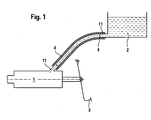
- FIGS. 1 to 25 For the description of FIGS. 1 to 25 the same reference numerals are used for the same components.
- FIG. 1 From the FIG. 1 is a partial area of a hydraulic route of a vehicle shown schematically. It can be seen that an actuator 3, a master cylinder 1 can be acted upon with force. A connecting piece of this master cylinder is designed as a plug-in part 11. Likewise, a fluid reservoir 2 has a connecting piece designed as a plug-in part 11. These two connecting pieces 11 are connected via a formed as a sleeve part fluid line 4, which may be a pipe or a hose. A connecting element 15 or 26 according to the invention is used to realize a sealing and axial force-retaining connection.
- This connecting element 15 is formed from a conically shaped rotoationssymmetrischen main body 16 having a thickness b and a rotational axis 34, the lateral surface has a slot 17 with a width 21. Furthermore, it has an inner diameter 19 and a cone angle 24. Its axial extent L1 is limited by the outer diameter 20.
- FIG. 3 shows a further embodiment of the securing element 15 according to the invention in the form of a provided with recesses 22 base body 16, whose thickness b is so small that it represents a disc.
- This securing element 15 has an inner diameter 19 and an outer diameter 20.
- This possibility would be on the inner diameter 19 also recesses 23 distributed around the circumference.
- this securing element 15 has a recess in the form of a slot 17, which, however, is not absolutely necessary, since the required elasticity is already achieved by the recesses.
- FIG. 3a shows the fuse element 15 FIG. 3 in a side view, from which the lateral axis inclined to the rotational axis 34 can be seen.
- FIG. 4 represents a cross-sectional view of a connection of a male part 11 with a sleeve part 4 by means of a securing element 15.
- the end portion of the male member 11 is provided at least with a circumferential groove 13.
- an annular surface is formed, which serves as a stop 14 for at least one end face of the securing element 15.
- the depth t of the groove 13 is to adjust the formation of the stop 14 of the thickness b of the base body 16 of the securing element 15. From this FIG. 4 It can also be seen that the end region of the sleeve part 4 has a widening 6.
- This expansion 6 has the same width L, which is adapted to the width of the groove 13.
- this widening 6 has a cone angle 24 to the rotation axis 34.
- a reduction in diameter in the form of a collar 4a whereby a disc-shaped surface is formed, which forms a stop 8 for the securing element 15.
- the inner diameter of the collar 4a is designed so that it corresponds to the outer diameter of the male part 11.
- the stop surface 8 or the depth of the widening 6 for forming the stop surface is to be chosen so that it corresponds at most to the thickness b of the base body 16.
- FIGS. 5 to 8 Further design possibilities of the end regions of plug-in part 11 and sleeve part 4 are shown in the connection region or its end region.
- the end portion of the sleeve part 4 is designed stepwise, so that not only a widening 6 is provided for receiving the securing element 15, but is also extended to receive the sealing element 30. It is important in all figures that stops are generated by constrictions or surveys between male part 11 and sleeve part 4, which serve on the one hand for receiving the sealing element 30 and the securing element 15 wherein these attacks in the area of the fuse element 15 at the same time serve to realize a snap connection.
- both FIGS. 4 to 8 the assembly of the male part 11 with the sleeve part 4 takes place in that either the sealing element 30 is inserted into a groove provided in the sleeve part 4 or inserted into a groove 9 of the male part 11 and thus preassembled.
- the sealing element 30 can be held without groove 13 only by friction on one of the components 4 and 11.
- the securing element 15 is inserted by radial expansion in the intended groove 13 of the male part 11 and thus also pre-assembled. Subsequently, the end portion of the sleeve part 4 is pushed over both components 30 and 15.
- the guide surface of the male part 11 and the sleeve part 4 is used for the conically shaped widening 6 of the sleeve part 4.
- the already a cone angle 24 having fuse element 15 is compressed when pushing the sleeve part 4 on the male part 11 in the radial direction. In this way, this securing element 15 is biased in the radial direction, wherein it rests with its end faces in each case on the stop 8 and the stop 14.
- FIGS. 4 to 8 represent possible embodiments for receiving a securing element between the male part 11 and the sleeve part 4.
- FIGS. 9 to 15 show possible embodiments of the design of a securing element 26, which completely or at least partially surrounds the lateral surfaces of both the male part 11 and the sleeve part 4 in the connecting region.
- a securing element 26 which has an annular base body 28a, on which in axial direction a plurality of latching hooks 29 are arranged distributed on the circumference.
- This securing element 26 is first mounted radially on a component. After the axial guiding of the components during assembly, this ensures their axial fixation.
- this fuse element 26 is shown as a single part. From this figure it can be seen that the annular base body 28a is C-shaped. On the circumference of this main body 28a a plurality of latching hooks 29 are arranged distributed in the axial direction, which preferably form a part of the main body 28a.
- the inner diameter 28b is to be chosen so that it is adapted to the diameter of the male part 11 at the designated receiving location.
- FIG. 11 Represents a cross-section of the connection FIG. 9 out of this FIG. 11 it can be seen that for receiving the annular base body 28a of the securing element 26, the plug-in part 11 has a groove 13 with a depth t.
- the main body 28a forms with its annular surface in the radial direction an axial stop 14a on the wall of the groove 13.
- the end region of the sleeve part 4 is in this case formed so that a stop 8a is formed by the step-like change in the outer diameter. To form this step, the end region has a radial extension for receiving a sealing element 30.
- the length 29a of the latching hooks is determined by the distance of the stops 14a and 8a.
- FIG. 12 shows a further possible embodiment of the end portion of the male part 11 and the sleeve part 4, in turn, the stops 14a and 8a formed by means of the securing element 26 are bridged.
- this fuse element 26 show the FIGS. 13 to 25 on, with this in the FIGS. 13 to 21 as a wire body 27 and in the FIGS. 22 to 25 designed as a plastic clip.
- This wire body 27 is in the FIGS. 13 to 17 essentially formed of two mutually parallel rings or wires 27b, which are self-contained or not closed. If they are not closed they form a C, like from the FIG. 14 evident.
- wires 27a running in the axial direction, these wires 27b are spaced apart from one another and simultaneously connected to one another.
- the wires 27b have twisting ends 27c, by means of which the respective ends of the wires 27b forming a ring can be connected to one another by twisting, whereby a different connection method, such as soldering, can be dispensed with.
- FIGS. 18 to 21 show wire body 27, in which the securing element 26 is formed substantially from axially extending wires 27a, wherein the radial shaping of these wires 27a connected in the radial direction sections of the wires 27b takes place.
- the length of the wires 27a is, as in the figures described above, dependent on the axially to be covered by the securing element 26 area and adjusted accordingly.
- a special shape of the wire body is in the FIGS. 20 and 21 shown. Here, only one extending in the radial direction, in this case a ring forming, wire 27b for shaping, on which distributed over the circumference a plurality of wires 27a are arranged.
- the wire ring 27b is welded to these wires 27a.
- the ends of the wires 27a are bent in a hook-shaped manner in the direction of the rotation axis 34 of the components 4 and 11, so that a bias voltage is generated during the assembly of this securing ring 26 to achieve a clip effect.
- FIG. 15 shows the connection according to FIG. 13 in a sectional view.
- This sectional view shows the components to be connected 4 and 11 with the intermediate seal 30 with the circumference of the connection encompassing connecting element 26 and is representative of the FIGS. 13 to 25 ,
- FIGS. 22 to 25 show the securing element 26 in the form of a plastic clip 35.
- This can either have a sleeve-shaped base body, as in the Figures 24 and 25 represented, or from individual webs 35a are formed.
- this clip 35 has the shape of a "C"'s.
- Both the base body and the webs 35a are bounded in the axial direction by collars 31, 32.
- These collars 31, 32 serve that in the final assembly, in which the sleeve part 4 is pushed over the end portion of the preassembled with the sealing element 30 male member 11, the clip 35 in the axial direction over the two stops 8a and 14a of male part 11 and sleeve part 4 snaps and this embraces it.
- a connection is made in both the radial and in the axial direction.
Landscapes
- Engineering & Computer Science (AREA)
- General Engineering & Computer Science (AREA)
- Mechanical Engineering (AREA)
- Braking Arrangements (AREA)
- Transmission Of Braking Force In Braking Systems (AREA)
Applications Claiming Priority (1)
| Application Number | Priority Date | Filing Date | Title |
|---|---|---|---|
| DE102006057417 | 2006-12-06 |
Publications (2)
| Publication Number | Publication Date |
|---|---|
| EP1930642A2 true EP1930642A2 (fr) | 2008-06-11 |
| EP1930642A3 EP1930642A3 (fr) | 2009-08-12 |
Family
ID=39154002
Family Applications (1)
| Application Number | Title | Priority Date | Filing Date |
|---|---|---|---|
| EP07022850A Withdrawn EP1930642A3 (fr) | 2006-12-06 | 2007-11-26 | Elément de retenue |
Country Status (1)
| Country | Link |
|---|---|
| EP (1) | EP1930642A3 (fr) |
Cited By (3)
| Publication number | Priority date | Publication date | Assignee | Title |
|---|---|---|---|---|
| FR2970229A1 (fr) * | 2011-01-12 | 2012-07-13 | Peugeot Citroen Automobiles Sa | Reservoir de liquide de frein et dispositif de freinage compact le comportant |
| US20230392731A1 (en) * | 2020-12-03 | 2023-12-07 | Mueller International, Llc | Grip ring |
| US12449071B2 (en) | 2022-05-25 | 2025-10-21 | Mueller International, Llc | Compression fitting |
Citations (2)
| Publication number | Priority date | Publication date | Assignee | Title |
|---|---|---|---|---|
| DE19529830C1 (de) | 1995-08-12 | 1997-03-06 | Ebern Fahrzeugtech Gmbh | Verbindungsleitung zwischen Geberzylinder und Ausgleichsbehälter einer hydraulischen Betätigungseinrichtung, insbesondere einer Kraftfahrzeug-Kupplungsbetätigung |
| DE19912351A1 (de) | 1999-03-19 | 2000-09-21 | Mannesmann Sachs Ag | Zur Befestigung an einem Anschlußstutzen vorgesehenes Anschlußstück |
Family Cites Families (4)
| Publication number | Priority date | Publication date | Assignee | Title |
|---|---|---|---|---|
| DE3728898A1 (de) * | 1987-08-29 | 1989-03-09 | Karl Liedgens | Schnappverbindung mittels sprengring fuer drehbare gelenke mit abdichtung |
| DE4413572A1 (de) * | 1994-04-19 | 1995-10-26 | Voss Armaturen | Steckverbinder für Druckleitungssysteme |
| GB0421808D0 (en) * | 2004-10-01 | 2004-11-03 | Imi Norgren Ltd | Coupling device |
| DE202004015506U1 (de) * | 2004-10-06 | 2006-02-16 | Voss Automotive Gmbh | Steckverbindung für Druckmittelsysteme |
-
2007
- 2007-11-26 EP EP07022850A patent/EP1930642A3/fr not_active Withdrawn
Patent Citations (2)
| Publication number | Priority date | Publication date | Assignee | Title |
|---|---|---|---|---|
| DE19529830C1 (de) | 1995-08-12 | 1997-03-06 | Ebern Fahrzeugtech Gmbh | Verbindungsleitung zwischen Geberzylinder und Ausgleichsbehälter einer hydraulischen Betätigungseinrichtung, insbesondere einer Kraftfahrzeug-Kupplungsbetätigung |
| DE19912351A1 (de) | 1999-03-19 | 2000-09-21 | Mannesmann Sachs Ag | Zur Befestigung an einem Anschlußstutzen vorgesehenes Anschlußstück |
Cited By (4)
| Publication number | Priority date | Publication date | Assignee | Title |
|---|---|---|---|---|
| FR2970229A1 (fr) * | 2011-01-12 | 2012-07-13 | Peugeot Citroen Automobiles Sa | Reservoir de liquide de frein et dispositif de freinage compact le comportant |
| US20230392731A1 (en) * | 2020-12-03 | 2023-12-07 | Mueller International, Llc | Grip ring |
| US12565954B2 (en) * | 2020-12-03 | 2026-03-03 | Mueller International, Llc | Grip ring |
| US12449071B2 (en) | 2022-05-25 | 2025-10-21 | Mueller International, Llc | Compression fitting |
Also Published As
| Publication number | Publication date |
|---|---|
| EP1930642A3 (fr) | 2009-08-12 |
Similar Documents
| Publication | Publication Date | Title |
|---|---|---|
| EP1805447B1 (fr) | Raccord enfichable resistant a la traction | |
| DE4041679A1 (de) | Rohrverschraubung | |
| EP1528309B1 (fr) | Raccord vissé pour des tuyaux à collerettes | |
| EP0327080B1 (fr) | Raccord pour tuyau | |
| EP1070215A1 (fr) | Dispositif pour raccorder une tubulure, une piece de robinetterie ou un raccord tubulaire a un tuyau | |
| DE112012002695B4 (de) | Schlauchkupplung, insbesondere für hydraulische Hochdruckleitungen eines Ausrücksystems | |
| DE3705610A1 (de) | Loesbare steckverbindung fuer rohrleitungen | |
| EP2357390A2 (fr) | Dispositif de raccordement pour un tuyau | |
| WO2005046906A1 (fr) | Procede et dispositif pour etablir une liaison serree entre tubes au niveau d'un raccord | |
| EP1930642A2 (fr) | Elément de retenue | |
| DE102007056882A1 (de) | Sicherungselement | |
| EP1953441A2 (fr) | Conduite dotée d'une pièce de raccordement | |
| DE102010054251A1 (de) | Anbindung einer Leitung | |
| DE10200574C1 (de) | Steckverbindung für den Anschluß von Rohrleitungen | |
| DE102007024133A1 (de) | Verfahren und Vorrichtung zum Verbinden eines Anschlussteils mit einer flexiblen Leitung | |
| DE19748623B4 (de) | Preßverbindung | |
| DE102007025406A1 (de) | Verfahren und Anordnung zur Verbindung von Leitungsenden | |
| DE102013208548A1 (de) | Verbindungssystem und Verfahren zum Verbinden von fluidführenden Bauteilen | |
| EP2072878A2 (fr) | Dispositif de raccordement pour un tuyau souple métallique ondulé | |
| EP2366932A1 (fr) | Raccord par mandrinage et connexion entre un raccord par mandrinage et un tuyau | |
| DE10107465C1 (de) | Steckverbindung für Rohrleitungen | |
| DE29822752U1 (de) | Nichtlösbare Rohrverbindung | |
| EP1479961B1 (fr) | Raccord à sertir | |
| EP3090909B1 (fr) | Fiche de raccordement fluidique | |
| DE102011107148A1 (de) | Steckverbinder |
Legal Events
| Date | Code | Title | Description |
|---|---|---|---|
| PUAI | Public reference made under article 153(3) epc to a published international application that has entered the european phase |
Free format text: ORIGINAL CODE: 0009012 |
|
| AK | Designated contracting states |
Kind code of ref document: A2 Designated state(s): AT BE BG CH CY CZ DE DK EE ES FI FR GB GR HU IE IS IT LI LT LU LV MC MT NL PL PT RO SE SI SK TR |
|
| AX | Request for extension of the european patent |
Extension state: AL BA HR MK RS |
|
| PUAL | Search report despatched |
Free format text: ORIGINAL CODE: 0009013 |
|
| AK | Designated contracting states |
Kind code of ref document: A3 Designated state(s): AT BE BG CH CY CZ DE DK EE ES FI FR GB GR HU IE IS IT LI LT LU LV MC MT NL PL PT RO SE SI SK TR |
|
| AX | Request for extension of the european patent |
Extension state: AL BA HR MK RS |
|
| AKX | Designation fees paid | ||
| STAA | Information on the status of an ep patent application or granted ep patent |
Free format text: STATUS: THE APPLICATION IS DEEMED TO BE WITHDRAWN |
|
| 18D | Application deemed to be withdrawn |
Effective date: 20100213 |
|
| REG | Reference to a national code |
Ref country code: DE Ref legal event code: 8566 Ref country code: DE Ref legal event code: R108 Effective date: 20100727 |
|
| P01 | Opt-out of the competence of the unified patent court (upc) registered |
Effective date: 20230523 |