EP1931008A2 - Verfahren und Vorrichtung zur Regulierung von Stromanomalien in einem Stromleitungsnetz eines Kraftfahrzeugs - Google Patents
Verfahren und Vorrichtung zur Regulierung von Stromanomalien in einem Stromleitungsnetz eines Kraftfahrzeugs Download PDFInfo
- Publication number
- EP1931008A2 EP1931008A2 EP20070301606 EP07301606A EP1931008A2 EP 1931008 A2 EP1931008 A2 EP 1931008A2 EP 20070301606 EP20070301606 EP 20070301606 EP 07301606 A EP07301606 A EP 07301606A EP 1931008 A2 EP1931008 A2 EP 1931008A2
- Authority
- EP
- European Patent Office
- Prior art keywords
- value
- organ
- current
- managed
- vehicle
- Prior art date
- Legal status (The legal status is an assumption and is not a legal conclusion. Google has not performed a legal analysis and makes no representation as to the accuracy of the status listed.)
- Withdrawn
Links
- 238000000034 method Methods 0.000 title claims abstract description 41
- 230000002159 abnormal effect Effects 0.000 title claims description 14
- 238000009429 electrical wiring Methods 0.000 title 1
- 210000000056 organ Anatomy 0.000 claims description 77
- 230000007257 malfunction Effects 0.000 claims description 12
- 238000012544 monitoring process Methods 0.000 claims description 9
- 230000009471 action Effects 0.000 claims description 7
- 238000012360 testing method Methods 0.000 claims description 4
- 230000002618 waking effect Effects 0.000 claims description 3
- 230000001105 regulatory effect Effects 0.000 abstract 1
- 238000007726 management method Methods 0.000 description 13
- 230000000694 effects Effects 0.000 description 6
- 230000004913 activation Effects 0.000 description 4
- 238000004891 communication Methods 0.000 description 4
- 230000009849 deactivation Effects 0.000 description 3
- 230000008569 process Effects 0.000 description 3
- 230000033228 biological regulation Effects 0.000 description 2
- 230000007423 decrease Effects 0.000 description 2
- 230000007547 defect Effects 0.000 description 2
- 238000010616 electrical installation Methods 0.000 description 2
- 230000000750 progressive effect Effects 0.000 description 2
- 230000004044 response Effects 0.000 description 2
- 238000005096 rolling process Methods 0.000 description 2
- 230000001960 triggered effect Effects 0.000 description 2
- 238000006677 Appel reaction Methods 0.000 description 1
- 240000008042 Zea mays Species 0.000 description 1
- 230000003416 augmentation Effects 0.000 description 1
- 230000005540 biological transmission Effects 0.000 description 1
- 239000004020 conductor Substances 0.000 description 1
- 238000010586 diagram Methods 0.000 description 1
- 230000004064 dysfunction Effects 0.000 description 1
- 238000010438 heat treatment Methods 0.000 description 1
- 238000009434 installation Methods 0.000 description 1
- 238000005259 measurement Methods 0.000 description 1
- 239000000155 melt Substances 0.000 description 1
- 230000004224 protection Effects 0.000 description 1
- 230000001681 protective effect Effects 0.000 description 1
- 230000009467 reduction Effects 0.000 description 1
- 230000001052 transient effect Effects 0.000 description 1
- 238000012795 verification Methods 0.000 description 1
Images


Classifications
-
- H—ELECTRICITY
- H02—GENERATION; CONVERSION OR DISTRIBUTION OF ELECTRIC POWER
- H02H—EMERGENCY PROTECTIVE CIRCUIT ARRANGEMENTS
- H02H3/00—Emergency protective circuit arrangements for automatic disconnection directly responsive to an undesired change from normal electric working condition with or without subsequent reconnection ; integrated protection
- H02H3/08—Emergency protective circuit arrangements for automatic disconnection directly responsive to an undesired change from normal electric working condition with or without subsequent reconnection ; integrated protection responsive to excess current
- H02H3/087—Emergency protective circuit arrangements for automatic disconnection directly responsive to an undesired change from normal electric working condition with or without subsequent reconnection ; integrated protection responsive to excess current for DC applications
-
- H—ELECTRICITY
- H02—GENERATION; CONVERSION OR DISTRIBUTION OF ELECTRIC POWER
- H02H—EMERGENCY PROTECTIVE CIRCUIT ARRANGEMENTS
- H02H3/00—Emergency protective circuit arrangements for automatic disconnection directly responsive to an undesired change from normal electric working condition with or without subsequent reconnection ; integrated protection
- H02H3/006—Calibration or setting of parameters
-
- H—ELECTRICITY
- H02—GENERATION; CONVERSION OR DISTRIBUTION OF ELECTRIC POWER
- H02H—EMERGENCY PROTECTIVE CIRCUIT ARRANGEMENTS
- H02H3/00—Emergency protective circuit arrangements for automatic disconnection directly responsive to an undesired change from normal electric working condition with or without subsequent reconnection ; integrated protection
- H02H3/02—Details
- H02H3/04—Details with warning or supervision in addition to disconnection, e.g. for indicating that protective apparatus has functioned
- H02H3/046—Signalling the blowing of a fuse
Definitions
- the present invention relates to a method and a device for managing abnormal currents in a motor vehicle electrical network.
- the invention relates to a method and device that can be used during the standby periods of current-consuming devices installed in a vehicle.
- consumer organ is meant any type of electrical, electronic, electromechanical or electrohydraulic member installed in an electrical network.
- the conductors of an electrical distribution network are protected by fuses.
- the principle of the fuse is to melt when the intensity of the current flowing through it becomes too high, thus causing the power supply of the circuit precisely where it is installed.
- the fuses are calibrated such that they accept the nominal currents of the consumer bodies downstream.
- an electrical network like that of a motor vehicle
- phenomena of local increase of resistance can intervene, and these phenomena have the specificity to create a current lower than the sizes of the protections, but locally sufficient to heat internally the equipment.
- the invention aims to remedy this drawback by proposing a method for managing abnormal currents in an electrical network of a stationary vehicle.
- stationary vehicle we mean a vehicle whose engine is cut, and all the consumer organs are at their standby consumption.
- the figure 1 shows on the axis 10 the activation or deactivation of the management method according to the different phases of life of the vehicle, presented on the axis 11.
- a stopping phase of a vehicle can be characterized by two different states of the vehicle, these states being distinguished according to customer events on the vehicle.
- the first state corresponding to the absence of the customer in the vehicle, without any electrical / electronic service activated.
- the vehicle communication networks "fall asleep” gradually to reach a stable state corresponding to a phase 14 called “consumer watch”.
- the watch currents are quantifiable and any abnormal current becomes identifiable.
- the management method is then active, this active mode being represented by the state 1 on the figure 1 .
- the second state corresponds to a phase "stop with performance in operation" 13.
- a user is present in the vehicle, and it activates certain services prohibiting the standby communication networks of the vehicle.
- the consumption profile of the consumer organs is not controllable, and the management method is therefore inactive in this case, as illustrated in FIG. figure 1 .
- the limitation may consist in a reduction of the power supply, but while maintaining a certain value of current, non-zero, in the organ, or else in a limitation that may go as far as the total breaking of the power supply. food.
- the method is such that the value of the measured current is the value of the current in the organ to be managed.
- the organs implanted in a vehicle sometimes require a permanent power supply for functional needs even during the waking periods of these organs.
- the method is such that the current consumed by the member is measured during the standby period.
- the method comprises the step, in the case where the measured value is greater than the reference value, and before limiting the power supply, to check whether the organ to manage has received a wake up order. If this is the case, the current limitation is then inhibited.
- the wake-up command is, for example, sent by the organ to be managed following an action initiated by a user. of the vehicle or by another member of the electronic circuit of the vehicle.
- An action initiated by a user is, for example, the command to open or start the vehicle.
- the abnormal currents in an organ may be due to an error in the reception or transmission of the sleep order, or to a malfunction of the organ.
- these problems of error or malfunction appear at the level of a software product implanted in the organ.
- a simple power failure and then supply of the consumer device, involving a restart and a simple reset of the software can sometimes be enough to correct the malfunction.
- the organs are also generally equipped with a voltage below which a restart occurs.
- the method is such that, in the case where a restart voltage is assigned to an organ to be managed, and when the voltage across the body reaches this restart voltage, the organ to be managed restarts. , and we count the number of successive reboots.
- the method is such that, in the case where the restart voltage has been reached, but the number of successive restarts is less than a determined value, for example three, the current limitation.
- the warning signal is, for example, intended for a user of the vehicle, and takes the form of a diode that lights up on the dashboard of the vehicle, or a beep, or a text displayed on a dashboard screen.
- the method will be such that the three actions mentioned are performed, simultaneously or successively, when an organ is always in default after three successive restarts.
- the method comprises the step of regularly testing the body to verify if the fault responsible for the current leak has been corrected.
- this defect may have been repaired by a person outside the vehicle, or it may have been resolved internally to the electronic circuit of the vehicle. In any case, it is useful to regularly check the state of this organ, to avoid leaving a functioning organ in the idle state.
- the method comprises, in one embodiment, the step of closing the current supply circuit of the electrical member, which allows the body of return to normal operation.
- the device also comprises, in one embodiment, means for measuring time.
- the device may have a global or local implementation on the distribution network.
- the current monitoring block makes it possible, for example, to acquire the transited current on one or more distribution lines of the electrical installation.
- the block of electric current limitation meanwhile, in particular allows to limit or cut the electric current flowing on one or more distribution lines of the electrical installation.
- the control unit block is, in one embodiment, composed of inputs / outputs and its function is to control and manage the current limiting and current monitoring blocks.
- the device is such that the measured current value is the current value in the organ to be managed.
- the device comprises means for, in the case where the measured value is greater than the reference value, to check whether the organ to be managed has received a wake-up command, the power limitation means being deactivated in case of awakening.
- the device is such that, in the case where a restart voltage is assigned to an organ to be managed, and when the voltage across the body reaches this restart voltage, the organ to be managed restarts and increments a restart counter of the organ to be managed.
- the device is such that, when the value of the restart counter is less than a predetermined value, for example three, the power limitation means are deactivated.
- the device comprises means for, when the supply circuit of an organ is open, regularly test the body to check if the fault responsible for the current leak has been corrected.
- the device is such that, when the fault has been corrected, the current limiting means are deactivated.
- the invention also relates to a motor vehicle implementing a method as described above, and / or comprising a device as described above.
- the figure 2 allows to compare the effect of a management method according to the invention to the effect of an existing current limiting method, using a fuse.
- the graph of this figure represents the evolution in time 21 of the line current 20 flowing in a consumer member.
- the current value If corresponds to the limit value acceptable by the fuse, that is to say the value beyond which the fuse melts.
- a method according to the invention is active only when the organs of the vehicle in which it is installed are in a standby state.
- the maximum current value is that determined by the fuse rating, namely I f .
- a standby body normally consumes less power than a functioning body, and it is therefore useful for current limiting to occur at lower current values.
- the figure 3 shows, from a logical point of view, the implementation of a method according to the invention, in an electronic circuit for monitoring two consumer organs.
- These members 30 and 31, as well as the other elements present in the circuit, are powered by a battery 32, connected to the mass 33 of the vehicle body.
- the management method is implemented by a control unit 34.
- the activation or deactivation of this control unit 34 depends on the state of the organs present in the vehicle.
- the control unit 34 is informed of this state by means of sleep or awakening request signals from the organs communicated to it via the input 36.
- the unit 34 When it detects a sleep signal, the unit 34 takes into account the instantaneous value 39 of the current delivered by the battery 32 and transited on the line. This value is measured by a current measuring circuit.
- the unit 34 compares this value 39 with a reference value 37, corresponding to the typical standby consumption of the organ from which it has detected falling asleep.
- control unit 34 triggers the current limiting procedure via a current regulation circuit 38.
- This graph represents the evolution, in time 40, of two quantities representative of the state of a managed consumer organ, namely the state 41a of falling asleep of the organ, and the intensity 41b circulating in the organ.
- phase 42 When the organ is in normal operation or transient phase of life corresponding to the end of the rolling, and the beginning of the stop (phase 42), that is to say when the state 41a of sleep is at the "OFF" level, the intensity 41b varies normally. This phase corresponds to a customer leaving his vehicle, resulting in the gradual falling asleep of the communication networks of the vehicle after a certain time. A sleep request is then sent to the control unit, causing the activation of the monitoring.
- a monitoring phase 43 to detect any abnormal current.
- This monitoring phase corresponds to a stopping phase of the vehicle.
- Communication networks are asleep, consumers are at their standby power consumption levels.
- peaks of current 45 appear for periods t1 and t2. These current peaks are due to functional requirements, and therefore they should not be detected as abnormal currents.
- a time T max corresponding to the normal functional duration of consumption, has been set, and below which the limitation process has not been triggered.
- the durations t1 and t2 are shorter than the duration Tmax, and the current peaks have no consequence in the management of abnormal currents.
- phase 44 current peak 47 has a duration greater than the duration Tmax, without being accompanied by a wake up request.
- this consumption is considered abnormal by the control unit, which sets up a suitable response, by controlling the current limiting circuit block.
- suitable responses there may be mentioned the limitation to several current thresholds of the supply of the consumer organs, or the total power failure.
- the result of the limitation is that the current decreases, following the curve 48, while without limitation, it would have continued according to the abnormal operation illustrated by curve 49.
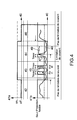
- the phase 46 illustrated on FIG. figure 4 corresponds to a transitional phase during which the customer rides in his vehicle.
- networks of Consumptions are woken up, and consumer organs leave their standby mode. This awakening results in the sending of a wake-up request to the control unit, resulting in the deactivation of the monitoring.
- V R When a restart voltage V R is assigned to the consumer member to be managed, this voltage generally having a low value, the device restarts as soon as the voltage across the consumer member reaches this value V R.
- the control unit 34 first initiates an initialization procedure 60. This procedure first involves checking that the vehicle is stationary, with all electronic services on standby. This verification is carried out, in particular, by means of the information signal 36. If it turns out that the vehicle is not stopping ("NO" event at the output of block 61), we return to the initialization step.
- the control unit then triggers the step 62 of acquisition of the current flowing in an organ to be managed.
- This current is measured by the circuit 35 and is compared, during the step 63, with a reference current 37. If the measured current is greater than the reference current (event "YES" on the reference graph), it It is necessary to activate the current supply limitation 65.
- control unit performs a last check 64, to verify that the organ has not received, in the meantime, wake up order. If such an order has been received (event "YES" at the output of block 64), the procedure is canceled, and we find sacred again in the initialization step.
- control unit then regularly performs a check 71 to detect a possible resolution of the fault. In the event that the fault is repaired, the procedure is initialized again.
Landscapes
- Emergency Alarm Devices (AREA)
- Emergency Protection Circuit Devices (AREA)
Applications Claiming Priority (1)
| Application Number | Priority Date | Filing Date | Title |
|---|---|---|---|
| FR0655400A FR2909813B1 (fr) | 2006-12-08 | 2006-12-08 | Procede et dispositif de gestion de courants anormaux dans un reseau electrique de vehicule automobile |
Publications (1)
| Publication Number | Publication Date |
|---|---|
| EP1931008A2 true EP1931008A2 (de) | 2008-06-11 |
Family
ID=38198460
Family Applications (1)
| Application Number | Title | Priority Date | Filing Date |
|---|---|---|---|
| EP20070301606 Withdrawn EP1931008A2 (de) | 2006-12-08 | 2007-11-30 | Verfahren und Vorrichtung zur Regulierung von Stromanomalien in einem Stromleitungsnetz eines Kraftfahrzeugs |
Country Status (2)
| Country | Link |
|---|---|
| EP (1) | EP1931008A2 (de) |
| FR (1) | FR2909813B1 (de) |
Family Cites Families (4)
| Publication number | Priority date | Publication date | Assignee | Title |
|---|---|---|---|---|
| FR2856851B1 (fr) * | 2003-06-26 | 2005-09-23 | Peugeot Citroen Automobiles Sa | Systeme de protection d'au moins une partie d'un reseau electrique de bord d'un vehicule automobile |
| DE10359736A1 (de) * | 2003-12-19 | 2005-07-14 | Conti Temic Microelectronic Gmbh | Sicherungssystem für einen Laststromkreis, insbesondere für ein Kraftfahrzeug |
| FR2870996B1 (fr) * | 2004-05-28 | 2006-08-04 | Cartier Technologies Soc Par A | Protection de circuit electrique en mode veille pour vehicule |
| FR2890797B1 (fr) * | 2005-09-14 | 2007-12-14 | Electricfil Automotive Soc Par | Dispositif pour surveiller l'apparition d'un courant de defaut a la sortie d'une source d'energie d'un vehicule |
-
2006
- 2006-12-08 FR FR0655400A patent/FR2909813B1/fr not_active Expired - Fee Related
-
2007
- 2007-11-30 EP EP20070301606 patent/EP1931008A2/de not_active Withdrawn
Also Published As
| Publication number | Publication date |
|---|---|
| FR2909813A1 (fr) | 2008-06-13 |
| FR2909813B1 (fr) | 2009-03-20 |
Similar Documents
| Publication | Publication Date | Title |
|---|---|---|
| FR2958587A1 (fr) | Procede de gestion d'un dispositif de repartition du couple moteur entre des trains de roues avant et arriere d'un vehicule. | |
| FR3055495A1 (fr) | Procede et dispositif de circuit pour couper une source de tension d'au moins un consommateur | |
| FR2893770A1 (fr) | Dispositif de gestion d'alimentation d'un reseau de consommateurs pour vehicule automobile | |
| FR3084468A1 (fr) | Procédé de diagnostic d’un moyen de commutation dans un véhicule automobile | |
| FR2681302A1 (fr) | Dispositif de direction assistee. | |
| FR3006462A1 (fr) | Procede et dispositif de lecture de l'etat de variables de contact d'un vehicule automobile | |
| EP2377276B1 (de) | Verfahren und vorrichtung zur steuerung des aufwachens von zu mindestens einem multiplexierten netzwerk gehörenden einrichtungen durch zählen von unbeabsichtigten aufweckungen | |
| EP3719947A1 (de) | Elektrische schutzverfahren und -systeme | |
| FR2966260A1 (fr) | Unite de commande electronique | |
| EP1931008A2 (de) | Verfahren und Vorrichtung zur Regulierung von Stromanomalien in einem Stromleitungsnetz eines Kraftfahrzeugs | |
| EP3631476B1 (de) | Einphasiger stromzähler | |
| FR2978879A1 (fr) | Procede de diagnostic d'un court-circuit dans un ensemble electrique d'un vehicule automobile comprenant une composante capacitive et dispositif de diagnostic | |
| FR2870996A1 (fr) | Protection de circuit electrique en mode veille pour vehicule | |
| FR2960093A1 (fr) | Dispositif de protection a associer a un dispositif de coupure de courant dans un circuit electrique a duree de vie accrue | |
| EP2991180B1 (de) | Elektrische trennschaltung für elektrische vorrichtungen, die in einem netz verbunden sind, steuerverfahren einer solchen schaltung | |
| EP1808743A1 (de) | Verfahren zur Steuerung einer Mikrokontrollerschaltung nach einem Nullrückstellungsvorgang und Mikrokontrollerschaltung zur Umsetzung dieses Verfahrens | |
| WO2025191219A1 (fr) | Dispositif et procédé de protection lors de la décharge d'un condensateur | |
| EP2626881A1 (de) | Elektrisches Sicherheitsverfahren und -vorrichtung für Erdschluss | |
| WO2012062788A1 (fr) | Dispositif et procédé de commande d'un radiateur électrique d'un système de ventilation, chauffage et/ou climatisation automobile | |
| FR2864363A1 (fr) | Systeme de controle de l'alimentation en energie d'organes fonctionnels d'un reseau de bord d'un vehicule | |
| EP1764892A1 (de) | Vorrichtung zur Überwachung eines Fehlerstromes am Ausgang einer Energiequelle eines Kraftfahrzeuges | |
| FR3151941A1 (fr) | Protection de batterie de vehicule automobile electrique ou hybride avec coupure pyrotechnique | |
| FR3019396A1 (fr) | Systeme de stabilisation de tension | |
| EP1492210A1 (de) | Scutzsystem für zumindest eines Teils eines Kraftfahrzeugbordnetzes | |
| FR2863402A1 (fr) | Procede et dispositif de surveillance et de securite d'une minuterie |
Legal Events
| Date | Code | Title | Description |
|---|---|---|---|
| PUAI | Public reference made under article 153(3) epc to a published international application that has entered the european phase |
Free format text: ORIGINAL CODE: 0009012 |
|
| AK | Designated contracting states |
Kind code of ref document: A2 Designated state(s): AT BE BG CH CY CZ DE DK EE ES FI FR GB GR HU IE IS IT LI LT LU LV MC MT NL PL PT RO SE SI SK TR |
|
| AX | Request for extension of the european patent |
Extension state: AL BA HR MK RS |
|
| STAA | Information on the status of an ep patent application or granted ep patent |
Free format text: STATUS: THE APPLICATION IS DEEMED TO BE WITHDRAWN |
|
| 18D | Application deemed to be withdrawn |
Effective date: 20120601 |