EP1931448B1 - Procede pour separer l'oxyde nitrique - Google Patents
Procede pour separer l'oxyde nitrique Download PDFInfo
- Publication number
- EP1931448B1 EP1931448B1 EP20060806813 EP06806813A EP1931448B1 EP 1931448 B1 EP1931448 B1 EP 1931448B1 EP 20060806813 EP20060806813 EP 20060806813 EP 06806813 A EP06806813 A EP 06806813A EP 1931448 B1 EP1931448 B1 EP 1931448B1
- Authority
- EP
- European Patent Office
- Prior art keywords
- nitrous oxide
- adsorbent material
- gas
- vent gas
- flowing
- Prior art date
- Legal status (The legal status is an assumption and is not a legal conclusion. Google has not performed a legal analysis and makes no representation as to the accuracy of the status listed.)
- Active
Links
Images

Classifications
-
- B—PERFORMING OPERATIONS; TRANSPORTING
- B01—PHYSICAL OR CHEMICAL PROCESSES OR APPARATUS IN GENERAL
- B01D—SEPARATION
- B01D53/00—Separation of gases or vapours; Recovering vapours of volatile solvents from gases; Chemical or biological purification of waste gases, e.g. engine exhaust gases, smoke, fumes, flue gases, aerosols
- B01D53/02—Separation of gases or vapours; Recovering vapours of volatile solvents from gases; Chemical or biological purification of waste gases, e.g. engine exhaust gases, smoke, fumes, flue gases, aerosols by adsorption, e.g. preparative gas chromatography
- B01D53/04—Separation of gases or vapours; Recovering vapours of volatile solvents from gases; Chemical or biological purification of waste gases, e.g. engine exhaust gases, smoke, fumes, flue gases, aerosols by adsorption, e.g. preparative gas chromatography with stationary adsorbents
- B01D53/047—Pressure swing adsorption
-
- B—PERFORMING OPERATIONS; TRANSPORTING
- B01—PHYSICAL OR CHEMICAL PROCESSES OR APPARATUS IN GENERAL
- B01D—SEPARATION
- B01D2257/00—Components to be removed
- B01D2257/40—Nitrogen compounds
- B01D2257/402—Dinitrogen oxide
-
- B—PERFORMING OPERATIONS; TRANSPORTING
- B01—PHYSICAL OR CHEMICAL PROCESSES OR APPARATUS IN GENERAL
- B01D—SEPARATION
- B01D2257/00—Components to be removed
- B01D2257/40—Nitrogen compounds
- B01D2257/404—Nitrogen oxides other than dinitrogen oxide
-
- B—PERFORMING OPERATIONS; TRANSPORTING
- B01—PHYSICAL OR CHEMICAL PROCESSES OR APPARATUS IN GENERAL
- B01D—SEPARATION
- B01D2257/00—Components to be removed
- B01D2257/80—Water
-
- B—PERFORMING OPERATIONS; TRANSPORTING
- B01—PHYSICAL OR CHEMICAL PROCESSES OR APPARATUS IN GENERAL
- B01D—SEPARATION
- B01D2259/00—Type of treatment
- B01D2259/40—Further details for adsorption processes and devices
- B01D2259/40001—Methods relating to additional, e.g. intermediate, treatment of process gas
-
- B—PERFORMING OPERATIONS; TRANSPORTING
- B01—PHYSICAL OR CHEMICAL PROCESSES OR APPARATUS IN GENERAL
- B01D—SEPARATION
- B01D2259/00—Type of treatment
- B01D2259/40—Further details for adsorption processes and devices
- B01D2259/40011—Methods relating to the process cycle in pressure or temperature swing adsorption
- B01D2259/40043—Purging
- B01D2259/4005—Nature of purge gas
- B01D2259/40052—Recycled product or process gas
-
- B—PERFORMING OPERATIONS; TRANSPORTING
- B01—PHYSICAL OR CHEMICAL PROCESSES OR APPARATUS IN GENERAL
- B01D—SEPARATION
- B01D2259/00—Type of treatment
- B01D2259/40—Further details for adsorption processes and devices
- B01D2259/40011—Methods relating to the process cycle in pressure or temperature swing adsorption
- B01D2259/40077—Direction of flow
- B01D2259/40081—Counter-current
-
- B—PERFORMING OPERATIONS; TRANSPORTING
- B01—PHYSICAL OR CHEMICAL PROCESSES OR APPARATUS IN GENERAL
- B01D—SEPARATION
- B01D2259/00—Type of treatment
- B01D2259/40—Further details for adsorption processes and devices
- B01D2259/402—Further details for adsorption processes and devices using two beds
-
- B—PERFORMING OPERATIONS; TRANSPORTING
- B01—PHYSICAL OR CHEMICAL PROCESSES OR APPARATUS IN GENERAL
- B01D—SEPARATION
- B01D2259/00—Type of treatment
- B01D2259/40—Further details for adsorption processes and devices
- B01D2259/404—Further details for adsorption processes and devices using four beds
-
- B—PERFORMING OPERATIONS; TRANSPORTING
- B01—PHYSICAL OR CHEMICAL PROCESSES OR APPARATUS IN GENERAL
- B01D—SEPARATION
- B01D53/00—Separation of gases or vapours; Recovering vapours of volatile solvents from gases; Chemical or biological purification of waste gases, e.g. engine exhaust gases, smoke, fumes, flue gases, aerosols
- B01D53/02—Separation of gases or vapours; Recovering vapours of volatile solvents from gases; Chemical or biological purification of waste gases, e.g. engine exhaust gases, smoke, fumes, flue gases, aerosols by adsorption, e.g. preparative gas chromatography
- B01D53/04—Separation of gases or vapours; Recovering vapours of volatile solvents from gases; Chemical or biological purification of waste gases, e.g. engine exhaust gases, smoke, fumes, flue gases, aerosols by adsorption, e.g. preparative gas chromatography with stationary adsorbents
- B01D53/047—Pressure swing adsorption
- B01D53/053—Pressure swing adsorption with storage or buffer vessel
-
- B—PERFORMING OPERATIONS; TRANSPORTING
- B01—PHYSICAL OR CHEMICAL PROCESSES OR APPARATUS IN GENERAL
- B01D—SEPARATION
- B01D53/00—Separation of gases or vapours; Recovering vapours of volatile solvents from gases; Chemical or biological purification of waste gases, e.g. engine exhaust gases, smoke, fumes, flue gases, aerosols
- B01D53/26—Drying gases or vapours
- B01D53/261—Drying gases or vapours by adsorption
-
- Y—GENERAL TAGGING OF NEW TECHNOLOGICAL DEVELOPMENTS; GENERAL TAGGING OF CROSS-SECTIONAL TECHNOLOGIES SPANNING OVER SEVERAL SECTIONS OF THE IPC; TECHNICAL SUBJECTS COVERED BY FORMER USPC CROSS-REFERENCE ART COLLECTIONS [XRACs] AND DIGESTS
- Y02—TECHNOLOGIES OR APPLICATIONS FOR MITIGATION OR ADAPTATION AGAINST CLIMATE CHANGE
- Y02C—CAPTURE, STORAGE, SEQUESTRATION OR DISPOSAL OF GREENHOUSE GASES [GHG]
- Y02C20/00—Capture or disposal of greenhouse gases
- Y02C20/10—Capture or disposal of greenhouse gases of nitrous oxide (N2O)
Definitions
- the present invention generally relates to a method of removing nitrous oxide. More specifically, the present invention relates to a method of using pressure swing adsorption and a nitrous oxide adsorbent material for removing the nitrous oxide in a vent gas formed from a synthesis of hydroxylamine and recycling remaining gases in the vent gas.
- US 4,507,271 discloses a method of removing nitrous oxide from a vent gas comprising N 2 O and at last one other gas.
- Nitrous oxide gas (N 2 O) is produced as a by-product in a synthesis of hydroxylamine. Hydroxylamine may be used to form a caprolactam that can be used to form nylon 6.
- Nylon 6 is an important polymer that is used throughout the world in carpets, apparel, upholstery, auto parts, and in many other products.
- hydroxylamine is formed from partially hydrogenating nitric oxide gas (NO) with hydrogen gas (H 2 ) in an aqueous medium including nitrogen gas (N 2 ) as an inert gas.
- NO nitric oxide gas
- H 2 hydrogen gas
- N 2 nitrogen gas
- the by-products include N 2 O.
- the N 2 O in addition to unused N 2 , H 2 , and NO along with water vapor (H 2 O), may be evacuated from the hydroxylamine as a moist gas mixture that may be disposed of or recycled.
- the gas mixture may also include contaminants including methane, carbon dioxide (CO 2 ), and carbon monoxide (CO).
- the gas mixture may be recycled along with H 2 and NO to reduce overall consumption of H 2 and NO.
- Adsorption can provide a more efficient and economic means for separating gasses than use of cryogenic distillation, absorption, or membrane-based systems. Adsorption can be used to separate a gas from the gas mixture that includes at least two gases that have different adsorption characteristics toward an adsorbent material.
- adsorption generally includes a co-coordinated cycling of a pressure or temperature of one or a plurality of adsorbent beds.
- the adsorbent bed includes the adsorbent material that preferentially adsorbs one or more gasses present in the gas mixture.
- Pressure swing adsorption generally includes a series of steps that change the pressure and/or flow direction of the gas mixture to achieve separation of a preferred gas from a series of non-preferred gasses. The number and nature of the steps involved in PSA may vary based on separation objectives.
- PSA typically includes flowing the gas mixture from a feed inlet of the adsorbent bed to a discharge end of the adsorbent bed, at an adsorption pressure.
- a gas in the gas mixture that has strong adsorption characteristics preferentially adsorbs onto the adsorbent material, while a gas with weak adsorption characteristics continues to flow through the adsorbent bed.
- the gas mixture flowing out of the discharge end of the adsorbent bed is substantially depleted of the gas preferentially adsorbed onto the adsorbent material.
- the gas with the strong adsorption characteristics flows from the feed inlet to the discharge end, the gas with the strong adsorption characteristics accumulates on the adsorbent material closest to the feed inlet. As the accumulation proceeds, the adsorbent material closest to the feed inlet becomes saturated first, followed by saturation of the entire adsorbent material in the direction of flow of the gas mixture.
- the gas with the strong adsorption characteristics breaks through the discharge end.
- the flow of the gas mixture is stopped before breakthrough occurs.
- the adsorption pressure is reduced to a level that allows the gas with the weak adsorption characteristics to be removed without excessively desorbing the gas adsorbed onto the adsorbent material.
- the adsorbent bed is further depressurized and the gas adsorbed onto the adsorbent material is removed from the bed.
- the adsorbent bed is then purged and re-pressurized to the adsorption pressure. Once this occurs, the adsorbent bed may be reused.
- adsorbent materials that may be used with PSA are dependent on the gas to be adsorbed, the gas mixture itself, and other factors that are well known to those skilled in the art.
- suitable adsorbent materials include zeolite molecular sieves, silica gel, activated carbon, and activated alumina.
- specialized adsorbent materials can be used.
- the efficiency of PSA depends on a variety of parameters including pressures, temperatures, volumes, and flow rates of gasses in PSA systems, time of the coordinated pressure cycling, types, sizes, and shapes of the adsorbent materials, dimensions of the adsorbent beds, and compositions of feed, product, purge, and other intermediate gas streams. Variations in these parameters can influence the cost and productivity of the PSA systems.
- Conventional PSA systems can remove N 2 O from the gas mixture.
- conventional PSA methods known in the art potentially form flammable gas mixtures of N 2 O, H 2 , and NO and have not exhibited a high selectivity for the N 2 O as compared to the H 2 O in the gas mixture.
- there remains an opportunity to develop a PSA method that effectively separates N 2 O from H 2 O in the gas mixture such that N 2 O of high purity can be removed from the gas mixture using a minimum number of PSA systems and the N 2 , H 2 , and NO can be efficiently recycled.
- the present invention provides a method of removing nitrous oxide from a vent gas.
- the vent gas includes the nitrous oxide and at least one other gas.
- the method includes the step of flowing the vent gas through a nitrous oxide adsorbent material.
- the nitrous oxide adsorbent material includes particles.
- the vent gas is flowed through the nitrous oxide adsorbent material such that the nitrous oxide is adsorbed onto the particles.
- the method also includes the step of forming a buffer zone, including nitrogen, adjacent to the nitrous oxide adsorbent material.
- the method further includes the step of flowing additional nitrous oxide through the nitrous oxide adsorbent material to displace the other gas.
- the method still further includes desorbing the nitrous oxide from the nitrous oxide adsorbent material.
- the method includes all of the steps of the first embodiment and additionally includes the step of forming a second buffer zone, including nitrogen, adjacent to the nitrous oxide adsorbent material after desorbing the nitrous oxide from the nitrous oxide adsorbent material.
- Flowing the additional nitrous oxide preferably displaces any of the vent gas from the nitrous oxide adsorbent material and allows the nitrous oxide to be removed from the nitrous oxide adsorbent material in high purity such that flammability is reduced.
- a method of removing nitrous oxide gas (N 2 O) from a vent gas including the N 2 O and at least one other gas is provided.
- the vent gas may include any gas or gas stream including the N 2 O.
- the vent gas hereafter, will be referred to as a third vent gas (3) , as the method of the present invention preferably utilizes first, second, and third vent gasses (1, 2, 3) .
- first and the second vent gasses (1, 2) need not be utilized and are optional.
- a first embodiment of the present invention includes the step of flowing the third vent gas (3) through a nitrous oxide adsorbent material (67) .
- the nitrous oxide adsorbent material includes particles, which will be described in greater detail below. There may be void spaces between the particles, which will also be described in greater detail below.
- the third vent gas (3) is flowed through the nitrous oxide adsorbent material (67) such that the nitrous oxide is adsorbed onto the particles.
- the first embodiment also includes the step of forming a buffer zone, including nitrogen, adjacent to the nitrous oxide adsorbent material (67) .
- the first embodiment further includes the step of flowing additional nitrous oxide through the nitrous oxide adsorbent material (67) to displace the other gas.
- the first embodiment still further includes the step of desorbing the nitrous oxide from the nitrous oxide adsorbent material (67) .
- the third vent gas (3) includes at least one other gas.
- the other gas includes, but is not limited to, hydrogen gas (H 2 ), the N 2 O, nitric oxide gas (NO), nitrogen gas, (N 2 ) and water vapor (H 2 O), in addition to other gasses such as methane, and trace gasses such as carbon dioxide (CO 2 ) and carbon monoxide (CO).
- H 2 hydrogen gas
- N 2 O nitric oxide gas
- NO nitrogen gas
- N 2 water vapor
- trace gasses such as carbon dioxide (CO 2 ) and carbon monoxide (CO).
- CO 2 carbon dioxide
- CO carbon monoxide
- the N 2 O is present in the third vent gas (3) in an amount of from 3 to 15, and more typically of from 5 to 11, mol %.
- the H 2 is typically present in the third vent gas (3) in an amount of at least 40 and more typically of at least 60, mol %.
- the NO and the N 2 are typically each present in the third vent gas (3) in an amount of less than 30 and more typically of less than 25, mol %, each.
- the H 2 O may be present in the third vent gas (3) in any amount and typically in an amount that saturates the third vent gas (3) at a temperature of from 30-60 °C at a pressure of greater than 2 bar absolute.
- methane may be present in the third vent gas (3) in an amount of from 0.1 to 3.0 mol % while CO 2 and CO may be present in an amount of from 10 to 100 parts per one million parts of the third vent gas (3) , each.
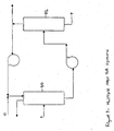
- Hydroxylamine may be formed in a reactor (26) from partially hydrogenating NO with H 2 in an aqueous medium including nitrogen gas (N 2 ) as an inert gas. Mixing the NO with the H 2 and the N 2 forms hydroxylamine in addition to a variety of by-products.
- the by-products include N 2 O.
- the N 2 O in addition to unused N 2 , H 2 , and NO along with H 2 O, may be evacuated from the reactor (26) as the first vent gas (1) , first introduced above.
- the first vent gas (1) may also include contaminants including methane, CO 2 and CO.
- the H 2 O may be removed from the first vent gas (1) to form the second and third vent gasses (2, 3), discussed in greater detail below. Ultimate removal of the N 2 O from the third vent gas (3) reduces safety and environmental hazards associated with flammability. Once removed, the N 2 O can be used as needed in other applications, commercially sold, or economically discarded.
- the first embodiment of the present invention may be completed using a variety of adsorption techniques including, but not limited to, pressure swing adsorption (PSA) techniques, any other adsorption techniques known in the art, and combinations thereof.
- PSA pressure swing adsorption
- the steps of the first embodiment are completed utilizing PSA techniques.
- the first vent gas (1) may be treated, as first introduced above.
- the first vent gas (1) may be treated to remove the H 2 O in two contents including a first content (4) and a second content (5) , respectively.
- the first content is removed using a removal unit (27), thereby forming the second vent gas (2) that includes some residual H 2 O.
- the second content (5) is removed using a first PSA system (29) , thereby forming the third vent gas (3) that includes a minimal amount of H 2 O.
- a minimal amount of H 2 O preferably includes an amount of H 2 O present in the third vent gas (3) of from 10 to 50, more preferably of from 15 to 40, and most preferably of from 20 to 25, parts of H 2 O per one million parts of the third vent gas (3) .
- the first content (4) of the H 2 O may be substantially removed from the first vent gas (1) through use of the removal unit (27) , first introduced above.
- the removal unit (27) is in fluid communication with the reactor (26) .
- the first vent gas (1) may be flowed from the reactor (26) into the removal unit (27).
- the removal unit (27) may include any apparatus that functions to remove the first content of the H 2 O from the first vent gas (1). Suitable examples of the first removal unit (27) include, but are not limited to, coolers, condensers, refrigerated dryers, gas scrubbers, and combinations thereof.
- the first removal unit (27) is a refrigerated dryer and removes the first content (4) of the H 2 O from the first vent gas (1) as liquid water. It is desirable to remove H 2 O from the first vent gas (1) because a low content of the H 2 O in the first vent gas (1) allows for a more effective adsorption of the N 2 O onto the nitrous oxide adsorbent material (67).
- the first vent gas (1) preferably flows into the first removal unit (27) at a pressure of from 1.38 to 6.21 bar [20 to 90 psia], more preferably of from 1.72 to 3.45 bar [25 to 50 psia], and most preferably of from 2.07 to 2.76 bar [30 to 40, psia], at a temperature of from 25 to 60°C.
- the refrigerated dryer may include a shell and a refrigeration system disposed within the shell.
- the refrigeration system may be generally defined by a housing including a moisture separator (43), a sump, a discharge conduit, and a drain to evacuate the liquid water from the refrigerated dryer.
- An evaporator may also be included in the housing of the refrigerated dryer.
- the first vent gas (1), flowing through the housing, may pass through the evaporator and be cooled to effect the removal of the first content (4) of the H 2 O from the first vent gas (1) thereby forming the second vent gas (2), as first introduced above.
- the first vent gas (1) may be cooled to a dew point such that the first content (4) of the H 2 O in the first vent gas (1) condenses to form the liquid water.
- the first vent gas (1) is preferably cooled to a dew point of from 5 to 30°C, more preferably of from 8 to 16°C, and most preferably of from 10 to 14°C.
- the first vent gas (1) may subsequently flow through the moisture separator (43).
- the moisture separator (43) preferably removes the first content of the H 2 O from the refrigerated dryer.
- the liquid water may flow from the moisture separator (43) through the discharge conduit to the sump.
- the sump preferably pumps the liquid water to the drain and evacuates the liquid water from the refrigerated dryer.
- the second vent gas (2) preferably exits the removal unit (27) through a removal outlet.
- the removal outlet may be in fluid communication with an inlet (33) of the first PSA system (29).
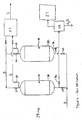
- the first PSA system (29) may be used to remove the second content (5) of the H 2 O and form the third vent gas (3), as seen in Figures 1 and 2 .
- the second vent gas (2) preferably enters the first PSA system (29) through the inlet (33) and exits through a first discharge end (35).
- the first PSA system (29) includes two first discharge ends (35).
- the first PSA system (29) also preferably includes a first adsorbent bed (30). It is contemplated that the first PSA system (29) may include a plurality of first adsorbent beds (30), as seen in Figure 2 . More preferably the first PSA system (29) includes two first adsorbent beds (30). Preferably, the first adsorbent bed (30) includes a water adsorbent material (31) that preferentially adsorbs H 2 O as compared to other gasses in the second vent gas (2).
- the first PSA system (29) also preferably includes a dry gas product tank (32), fluid movers (not shown,) valves, and instrumentation (not shown) that may be selected by one skilled in the art.
- the second vent gas (2) preferably flows into the first adsorbent bed (30) at a first adsorption pressure, and for a first pressurization time, from the inlet (33).
- the first adsorption pressure includes a pressure of from 1.38 to 6.21 bar [20 to 90, psia], more preferably of from 1.72 to 3.45 bar [25 to 50, psia], and most preferably of from 2.76 to 2.76 bar [30 to 40, psia].
- the H 2 O preferably adsorbs onto and saturates the water adsorbent material (31) closest to the inlet (33) for a first adsorption time.
- the water adsorbent material (31) includes, but is not limited to, hydrophilic adsorbents, hydrophobic adsorbents, polymeric adsorbents, activated carbon, carbon molecular sieve adsorbents, activated alumina, silica gel, zeolites including those with type A, X, Y, ZSM-5, silicalite, mordenite, and combinations thereof.
- the water adsorbent material (31) includes various grades of silica gel and alumina.
- the water adsorbent material (31) includes a silica gel commercially available from Grace Davison of Columbia, MD, under the trade name Davison 03.
- the silica gel has a high selectivity for the H 2 O over the N2, the H 2 , NO, and N 2 O thereby increasing an efficiency of removing the H 2 O from the second vent gas (2).
- the silica gel may also adsorb some of the N 2 O from the second vent gas (2). If this occurs, the N 2 O may be separated from the H 2 O with additional adsorption and desorption techniques.
- the other gasses such as CO 2 may also be removed from the second vent gas (2) using any adsorption method known in the art.
- the other gasses in the second vent gas (2) such as H 2 , NO, N 2 O, and N 2 , preferably flow out of the first discharge end (35) of the first adsorbent bed (30) and the third vent gas (3) is formed, as first introduced above.
- the third vent gas (3) preferably continues to flow (3) into the dry gas product tank (32) preferably in fluid communication with the first discharge end (35) of the first adsorbent bed (30).
- the H 2 O preferably adsorbs onto the water adsorbent material (31) immediately next to the saturated water adsorbent material (31) in a direction towards the first discharge end (35) . If all of the water adsorbent material (31) from the inlet (33) to the first discharge end (35) becomes saturated, the H 2 O may breakthrough the first adsorbent bed (30). Preferably, flow of the second vent gas (2) is stopped before breakthrough of the H 2 O from the first adsorbent bed (30).
- the first adsorbent bed (30) is preferably counter-currently depressurized to a pressure below that first adsorbent pressure for a first blow down time. It is to be understood that "counter-currently” includes a flow of a gas in an opposite direction of a flow of the second vent gas (2).
- the third vent gas (3) may be used to further counter-currently de-pressurize and purge the first adsorbent bed (30), at a first desorption pressure and a purge flow rate, to assist a desorption of the H 2 O from the water adsorbent material, thereby regenerating the first adsorbent bed (30).
- the first discharge end (35) and inlet (33) may be closed and a valve (36) and the purge valve (37) may be opened to allow the third vent gas (3) to flow through and out of the first adsorbent bed (30) and into the moisture separator (43).
- the first desorption pressure preferably includes a pressure of from 0.03 to 2.07 bar [0.5 to 30 psia], and more preferably from 0.07 to 1.03 bar [1 to 15, psia]. It is also contemplated that a variety of intermediate con-current depressurization steps and purges may be utilized to improve formation of the third vent gas (3). Also, the first adsorbent bed (30) may also be purged with nitrogen (12) to improve formation of the third vent gas (3).
- the third vent gas (3) enters into a second PSA system (65).
- the second PSA system (65) is similar to the first PSA system (29) including similar fluid movers, valves and instrumentation that are known to art. However, it is also contemplated that the second PSA system (65) may be different from the first PSA system (29).
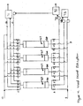
- the second PSA system (65) preferably includes the second adsorbent bed (66), and it is contemplated that the second PSA system (65) may include a plurality of second adsorbent beds (66). More preferably, the second PSA system (65) includes four second adsorbent beds (66), as seen in Figure 4 .
- the second adsorbent bed (66) includes the nitrous oxide adsorbent material (67).
- the nitrous oxide adsorbent material (67) may be disposed in any vessel known in the art.
- the second PSA system (65) also may include a light product or N 2 O lean product tank (71), an N 2 O product tank (72), a recycle tank (73), and fluid movers, valves, and instrumentation that are known in the art.
- the third vent gas (3) enters the second PSA system (65) through an inlet valve (A) at a second adsorption pressure and for a second pressurization time, and exits through a second discharge end (B).
- the second adsorption pressure includes a pressure of from 0.69 to 5.17 bar [10 to 75 psig], more preferably of from 1.03 to 2.76 bar [15 to 40 psig], and even more preferably of from 1.03 to 2.07 bar [15 to 30, psig]. Most preferably the second adsorption pressure is 1.03 bar [15 psig].
- the N 2 O preferably adsorbs onto and saturates the nitrous oxide adsorbent material (67) closest to the inlet valve (A) for a second adsorption time.
- the nitrous oxide adsorbent material (67) includes the particles, introduced above. There may be void spaces between the particles.
- the nitrous oxide adsorbent material (67) preferentially adsorbs N 2 O over H 2 , NO, N 2 , other gasses and trace components present in the third vent gas (3).
- the first embodiment of the present invention includes the step of flowing the third vent gas (3) through the nitrous oxide adsorbent material (67) such that the N 2 O adsorbs onto the particles. It is contemplated that the first embodiment may also include the step of flowing the third vent gas (3) through the void spaces of the particles.
- the nitrous oxide adsorbent material (67) includes, but is not limited to, hydrophilic adsorbents, hydrophobic adsorbents, polymeric adsorbents, activated carbon, carbon molecular sieve adsorbents, activated alumina, silica gel, zeolites including those with type A, X, Y, ZSM-5, silicalite, mordenite, and combinations thereof. More preferably the nitrous oxide adsorbent material (67) includes 5A zeolite, ZSM-5, and LiX.
- the nitrous oxide adsorbent material (67) includes a hydrophobic zeolite molecular sieve currently commercially available from UOP LLC of Des Plaines Il, under the trade name of HISIV-3000.
- HISIV-3000 Use of the HISIV-3000 allows for efficient adsorption and removal of the N 2 O from the third vent gas (3).
- the other gasses in the third vent gas (3) such as H 2 , NO, and N 2 , other gasses and trace components, known as a multi-component gas, preferably flow out of the second discharge end (B) of the second adsorbent bed (66).
- the multi-component gas flowing out of the second discharge end (B) flows into the light product tank (71). It is also contemplated that the multi-component gas may be used to purge the second adsorbent bed (66) for an N 2 O lean purge time.
- the N 2 O preferably adsorbs onto nitrous oxide adsorbent material (67) immediately next to the saturated nitrous oxide adsorbent material (67) in a direction towards the second discharge end (B). If all of the nitrous oxide adsorbent material (67) from the inlet valve (A) to the second discharge end (B) becomes saturated, the N 2 O may breakthrough. Preferably, flow of the third vent gas (3) is stopped before breakthrough of the N 2 O.
- the first embodiment of the present invention also includes the step of forming the buffer zone including N 2 adjacent to the nitrous oxide adsorbent material (67).
- the nitrous oxide adsorbent material (67) is isolated from the flow of the third vent gas (3) prior to the formation of the buffer zone.
- the N 2 (12) is flowed into the second adsorbent bed (66) through a first gas valve (C) at the second adsorption pressure, for an N 2 pressurization time, and at an N 2 purge rate, to form the buffer zone.
- the first embodiment includes the step of flowing the nitrogen counter-currently to the flow of the third vent gas (3) after the nitrous oxide adsorbent material (67) is isolated from the flow of the third vent gas (3).
- the step of flowing may include the step of flowing substantially pure N 2 O (13) through the void spaces.
- the additional N 2 O and/or the substantially pure N 2 O is flowed counter-currently to the flow of the third vent gas (3).
- the substantially pure N 2 O (13) is preferably counter-currently flowed at the second adsorption pressure, for an N 2 O rinse time, and at an N 2 O rinse rate, via a second gas valve (D) to displace the N 2 (12) and/or any third vent gas (3) in the void spaces, away from the second discharge end (B) of the second adsorbent bed (66).
- the buffer zone is preferably disposed between the additional N 2 O and the third vent gas (3) in the void spaces.
- the N 2 O may be desorbed from the nitrous oxide adsorbent material (67) in high purity. If the N 2 (12) and/or any third vent gas (3) in the void spaces is displaced away from the second discharge end (B), a first effluent, leaving inlet valve (A), is preferably produced. This first effluent may be recycled to back into the third vent gas (3).
- the flow of the substantially pure N 2 O (13) is stopped immediately before the N 2 is displaced out of the inlet valve (A) of the second adsorbent bed ( 66 ).
- the first embodiment also includes the step of desorbing the N 2 O from the nitrous oxide adsorbent material (67).
- a pressure of the second adsorbent bed (66) may be lowered through counter-current depressurization to a second desorption pressure for a second blow down time to desorb the N 2 O at a desorption rate and for a second desorption time, thereby producing a second effluent.
- the second effluent preferably flows out of the second adsorbent bed (66) via a third gas valve (F) and into the N 2 O product tank (72) via appropriate fluid movers (76), valves, and instrumentation that are well known in the art.
- the second effluent may include of from 7 to 100 mol % N 2 O, 50 to 90 mol % N 2 , 1 to 5 mol % NO, and 1 to 5 mol % H 2 . It is to be understood that any method known in the art may be used to desorb the N 2 O.
- the second desorption pressure includes a pressure of from 0.03 to 0.69 bar [0.5 to 10 psia], more preferably of from 0.03 to 0.41 bar [0.5 to 6 psia], and even more preferably of from 0.03 to 0.10 bar [0.5 to 1.5, psia]. Most preferably, the second desorption pressure is 0.07 bar [ 1 psia ].
- the first embodiment preferably includes the step of forming a second buffer zone, including the N 2 (12), adjacent to the nitrous oxide adsorbent material (67).
- the N 2 (12) is flowed into the second adsorbent bed (66) at the second desorption pressure to form the second buffer zone.
- the step of forming the second buffer zone includes the step of flowing the nitrogen counter-currently to the flow of the third vent gas (3).
- the second buffer zone preferably is used to displace any remaining N 2 O in the void spaces.
- the multi-component gas from the light product tank (71) is preferably flowed through the nitrous oxide adsorbent material (67) at the second desorption pressure, via a fourth gas valve (G) to re-pressurize the first adsorbent bed (30). It is also contemplated that the multi-component gas may be flowed through the nitrous oxide adsorbent material (67) and through the void spaces. Preferably, the multi-component gas is flowed counter-currently to the third vent gas (3).
- the N 2 (12) is preferably displaced from the void spaces in a third effluent such that additional amounts of the third vent gas (3) can be utilized.
- the third effluent flows via a fifth gas valve (E) to a recycle tank (73) via appropriate fluid movers (76), valves and instrumentation that are well known in the art.
- flow of the third effluent is stopped once the N 2 (12) is displaced from the void spaces. It is also contemplated that a variety of intermediate con-current and/or counter-current depressurization steps and purges may be utilized to improve recovery or purity of the N 2 O present in the second effluent.
- each of the additional PSA systems (50, 52) may be used in the present invention to increase a purity of the N 2 O present in the second effluent, as seen in Figure 3 .
- the additional PSA systems (50, 52) may be the same as the first and the second PSA systems (29, 65) or may be different. However, it is preferred that each of the additional PSA systems (50, 52) operate in a similar manner as the first and the second PSA systems (29, 65).
- each of the additional PSA systems (50, 52) preferably includes a second nitrous oxide adsorbent material.
- the second nitrous oxide adsorbent material is the same as the nitrous oxide adsorbent material (67). However, the second nitrous oxide adsorbent material may be different from the nitrous oxide adsorbent material (67).
- the method includes the steps of the first embodiment including the step of flowing the third vent gas (3) through the nitrous oxide adsorbent material (67) such that the N 2 O is adsorbed onto the particles.
- the second embodiment also includes the step of forming the buffer zone including the N 2 (12), adjacent to the nitrous oxide adsorbent material (67).
- the second embodiment also includes the step of flowing the additional N 2 O through the nitrous oxide adsorbent material (67) to displace the other gas.
- the second embodiment further includes the step of desorbing the N 2 O from the nitrous oxide adsorbent material (67).
- the N 2 O is desorbed by lowering a pressure of the second adsorbent bed (66) through counter-current depressurization.
- the second embodiment still further includes the step of forming the second buffer zone including the N 2 (12) adjacent to the nitrous oxide adsorbent material (67) after desorbing the N 2 O from the nitrous oxide adsorbent material (67). It is to be understood that the second embodiment may also include any and/or all of the steps of the first embodiment.
- Hydroxylamine can be formed in a reactor (26) by combining nitric oxide gas (NO), nitrogen gas (N 2 ), and hydrogen gas (H2) in an aqueous medium to partially hydrogenate the NO.
- NO nitric oxide gas
- N 2 nitrogen gas
- H2 hydrogen gas
- nitrous oxide gas N 2 O
- the first vent gas (1) typically includes approximately 67% H 2 , 14% NO, 9% N 2 , 4% H 2 O, 8% N 2 O, and a trace amount of other gasses such as methane, CO 2 and CO.
- the following examples utilize synthetic mixtures of the aforementioned gasses representative of a typical first vent gas (1).
- the synthetic mixtures of the gasses are hereafter referred to as "mixtures.”
- a first pressure swing adsorption (PSA) system (29) is employed and utilizes a first mixture of N 2 , N 2 O, and H 2 O.
- a second PSA system (65) is also employed and utilizes second and third mixtures.
- the second mixture includes N 2 and N 2 O, while the third mixture includes Helium (He) to represent H 2 , N 2 , NO, and also includes N 2 O.
- a removal unit (27) is not used with the first, second, and third mixtures.
- the first PSA system (29) includes a water adsorbent material (31) that has a high selectivity for the H 2 O, thereby allowing for removal of the H 2 O from the first mixture.
- Specific parameters used in the first PSA system (29) along with the results of the removal of the H 2 O from the first mixture are set forth in Table 1.
- a first pressurization time, a first adsorption time, and a first blow down time, included in Table 1, are as first introduced and described above.
- the first PSA system (29) includes two first adsorbent beds (30), bed A and bed B, respectively.
- the first adsorbent beds (30) are constructed from 5,1 cm (two inch) Sch 80 PVC pipe and include Davison 03 commercially available from Grace Davison of Columbia, MD, as the water adsorbent material (31).
- the length of the first adsorbent beds (30) is 13,9 cm (5.47 inches)
- the mass of the water adsorbent material (31) in bed A is 180.41 grams
- the mass of the water adsorbent material (31) in bed B is 180.43 grams
- the amount of H 2 O in the first mixture used in Table 1 is 50% relative humidity at 25°C and 2.14 bar [31 psia].
- H 2 O initially present includes an amount of H 2 O initially present in the first mixture.
- H 2 O finally present includes an amount of H 2 O finally present in the first mixture.
- the second PSA system (65) includes a nitrous oxide adsorbent material (67) that has a high selectivity for the N 2 O.
- a rinse with substantially pure N 2 O to aid in removal of the N 2 O from the nitrous oxide adsorbent material (67) is also utilized with the second PSA system (65).
- Specific parameters used in the second PSA system (65) along with the results of the removal of the N 2 O from the second and third mixtures, are set forth in Table 2.
- a second pressurization time, a second adsorption time, an N 2 pressurization time, an N 2 O rinse time, an N 2 O rinse rate, a second blow down time, a second desorption time, and a desorption rate, included in Table 2, are as first introduced and described above.
- the second PSA system (65) includes four second adsorbent beds (66), bed C, bed D, bed E, and bed F, respectively.
- the second adsorbent beds (66) are constructed from 2.5 cm (one inch) 304 SS pipe and include HISIV-3000 commercially available from UOP LLC of Des Plaines, Il, as the nitrous oxide adsorbent material (67).
- the length of the second adsorbent beds (66) is 69,6 cm (27.4 inches)
- the mass of the nitrous oxide adsorbent material (67) in bed C is 172.500 grams
- the mass of the nitrous oxide adsorbent material (67) in bed D is 172.489 grams
- the mass of the nitrous oxide adsorbent material (67) in bed E is 172.659 grams
- the mass of the nitrous oxide adsorbent material (67) in bed F is 172.508 grams.
- Examples 1 to 8 utilize the second mixture while example 9 utilizes the third mixture.
- the mixture concentration includes a percentage of N 2 O originally present in the second and third mixtures based on a total volume of the second and third mixtures, before the N 2 O is removed using the second PSA system (65).
- the mixture flow rate includes a rate that the second and third mixtures are introduced into the second PSA system (65).
- the purity of the N 2 O removed includes a measurement of the purity of the N 2 O that is removed from the second and third mixtures.
- the percent of the N 2 O removed includes a measurement of an amount of the N 2 O that is removed from the second and third mixtures as compared to a total amount of N 2 O present in the second and third mixtures, respectively.
- Computer simulations are also employed and are used to determine optimal N 2 O removal using an experimental PSA system. Initially, the computer simulation is verified against lab results of examples 2, 6 and 9 in Table 2. The specific parameters used in the computer simulations along with the expected results of the removal of the N 2 O, are represented by the Ideal Example, are set forth in Table 3. The desorption rate, the N 2 O rinse rate, and the N 2 purge rate, included in Table 3, are as described and set forth above.
- the Ideal Example includes parameters optimized for maximum removal of N 2 O from a hypothetical third vent gas (3) including H 2 , NO, N 2 O, NO, as well minor components such as methane, and CO 2 , similar to an actual third vent gas (3).
- the purity of the N 2 O exceeds 99% which is considered commercially pure and is suitable for commercial sale.
- the mixture concentration includes a percentage of N 2 O present in the mixture used in the computer simulations, before removal with the experimental PSA system.
- the mixture flow rate includes a rate that the mixture used in the computer simulations is introduced into the experimental PSA system.
Landscapes
- Chemical & Material Sciences (AREA)
- Engineering & Computer Science (AREA)
- Analytical Chemistry (AREA)
- General Chemical & Material Sciences (AREA)
- Oil, Petroleum & Natural Gas (AREA)
- Chemical Kinetics & Catalysis (AREA)
- Separation Of Gases By Adsorption (AREA)
- Treating Waste Gases (AREA)
Claims (17)
- Procédé de retrait de l'oxyde nitreux d'un gaz évacué comprenant l'oxyde nitreux et au moins un autre gaz, ledit procédé comprenant les étapes consistant à :faire circuler le gaz évacué à travers un matériau adsorbant l'oxyde nitreux comprenant des particules de telle sorte que l'oxyde nitreux soit adsorbé sur les particules ;former une zone tampon comprenant de l'azote adjacente au matériau adsorbant l'oxyde nitreux ;faire circuler de l'oxyde nitreux supplémentaire à travers le matériau adsorbant l'oxyde nitreux pour déplacer l'autre gaz ; etdésorber l'oxyde nitreux du matériau adsorbant l'oxyde nitreux.
- Procédé selon la revendication 1 comprenant en outre l'étape consistant à isoler le matériau adsorbant l'oxyde nitreux de la circulation du gaz évacué avant formation de la zone tampon.
- Procédé selon la revendication 2 dans lequel l'étape de formation de la zone tampon comprend l'étape consistant à faire circuler l'azote à contre-courant de la circulation du gaz évacué après que le matériau adsorbant l'oxyde nitreux a été isolé de la circulation du gaz évacué.
- Procédé selon la revendication 1 dans lequel l'étape de circulation de l'oxyde nitreux supplémentaire comprend la circulation d'oxyde nitreux sensiblement pur à travers le matériau adsorbant l'oxyde nitreux.
- Procédé selon la revendication 1 dans lequel l'étape de circulation de l'oxyde nitreux supplémentaire comprend la circulation de l'oxyde nitreux supplémentaire à contre-courant de la circulation du gaz évacué.
- Procédé selon la revendication 1 dans lequel le matériau adsorbant l'oxyde nitreux comprend les particules avec des espaces vides entre les particules et la zone tampon est disposée entre l'oxyde nitreux supplémentaire et le gaz évacué dans les espaces vides.
- Procédé selon la revendication 1 dans lequel le matériau adsorbant l'oxyde nitreux est disposé dans un lit d'adsorbant et l'étape de désorption de l'oxyde nitreux comprend l'étape consistant à abaisser la pression du lit d'adsorbant.
- Procédé selon la revendication 1 comprenant en outre
la formation d'une deuxième zone tampon comprenant l'azote adjacente au matériau adsorbant l'oxyde nitreux après désorption de l'oxyde nitreux du matériau adsorbant l'oxyde nitreux. - Procédé selon la revendication 8 comprenant en outre l'étape consistant à isoler le matériau adsorbant l'oxyde nitreux de la circulation du gaz évacué avant formation de la zone tampon.
- Procédé selon la revendication 9 dans lequel l'étape de formation de la zone tampon comprend l'étape consistant à faire circuler l'azote à contre-courant de la circulation du gaz évacué après que le matériau adsorbant l'oxyde nitreux a été isolé de la circulation du gaz évacué.
- Procédé selon la revendication 8 dans lequel l'étape de formation de la deuxième zone tampon comprend l'étape consistant à faire circuler l'azote à contre-courant de la circulation du gaz évacué.
- Procédé selon la revendication 8 dans lequel l'étape de circulation de l'oxyde nitreux supplémentaire comprend la circulation d'oxyde nitreux sensiblement pur à travers le matériau adsorbant l'oxyde nitreux.
- Procédé selon la revendication 8 dans lequel l'étape de circulation de l'oxyde nitreux supplémentaire comprend la circulation de l'oxyde nitreux supplémentaire à contre-courant du gaz évacué.
- Procédé selon la revendication 8 comprenant en outre l'étape consistant à faire circuler un courant gazeux multicomposant à travers le matériau adsorbant l'oxyde nitreux.
- Procédé selon la revendication 14 dans lequel l'étape de circulation du gaz multicomposant comprend la circulation du gaz multicomposant à contre-courant du gaz évacué.
- Procédé selon la revendication 8 dans lequel le matériau adsorbant l'oxyde nitreux comprend les particules avec des espaces vides entre les particules et la zone tampon est disposée entre l'oxyde nitreux supplémentaire et le gaz évacué dans les espaces vides.
- Procédé selon la revendication 8 dans lequel le matériau adsorbant l'oxyde nitreux est disposé dans un lit d'adsorbant et l'étape de désorption de l'oxyde nitreux comprend l'étape consistant à abaisser la pression du lit d'adsorbant.
Priority Applications (1)
| Application Number | Priority Date | Filing Date | Title |
|---|---|---|---|
| PL06806813T PL1931448T3 (pl) | 2005-09-27 | 2006-09-26 | Sposób usuwania podtlenku azotu |
Applications Claiming Priority (2)
| Application Number | Priority Date | Filing Date | Title |
|---|---|---|---|
| US72089105P | 2005-09-27 | 2005-09-27 | |
| PCT/EP2006/066720 WO2007039514A1 (fr) | 2005-09-27 | 2006-09-26 | Procede pour evacuer l'oxyde nitrique |
Publications (2)
| Publication Number | Publication Date |
|---|---|
| EP1931448A1 EP1931448A1 (fr) | 2008-06-18 |
| EP1931448B1 true EP1931448B1 (fr) | 2015-05-20 |
Family
ID=37622193
Family Applications (1)
| Application Number | Title | Priority Date | Filing Date |
|---|---|---|---|
| EP20060806813 Active EP1931448B1 (fr) | 2005-09-27 | 2006-09-26 | Procede pour separer l'oxyde nitrique |
Country Status (10)
| Country | Link |
|---|---|
| US (2) | US20080247928A1 (fr) |
| EP (1) | EP1931448B1 (fr) |
| JP (1) | JP5158717B2 (fr) |
| KR (1) | KR20080066929A (fr) |
| CN (1) | CN101272844B (fr) |
| BR (1) | BRPI0616341A2 (fr) |
| PL (1) | PL1931448T3 (fr) |
| RU (1) | RU2008116148A (fr) |
| UA (1) | UA92616C2 (fr) |
| WO (2) | WO2007039514A1 (fr) |
Families Citing this family (4)
| Publication number | Priority date | Publication date | Assignee | Title |
|---|---|---|---|---|
| US8535417B2 (en) * | 2008-07-29 | 2013-09-17 | Praxair Technology, Inc. | Recovery of carbon dioxide from flue gas |
| CN106731497B (zh) * | 2016-12-20 | 2023-12-08 | 杨刘月 | 一种硝酸工业尾气除碳提取n2o的纯化装置和工艺方法 |
| JP7100223B2 (ja) * | 2017-01-10 | 2022-07-13 | エマージング・コンパウンズ・トリートメント・テクノロジーズ・インコーポレイテッド | 再生可能な合成吸着媒体の処理能力を高めるよう汚染蒸気の吸着を向上させるためのシステムおよび方法 |
| CN115448810A (zh) * | 2022-11-11 | 2022-12-09 | 山东东岳化工有限公司 | 三氟甲烷中二氧化碳和氧化亚氮的去除方法和系统 |
Family Cites Families (11)
| Publication number | Priority date | Publication date | Assignee | Title |
|---|---|---|---|---|
| DE3244370A1 (de) * | 1982-12-01 | 1984-06-07 | Basf Ag, 6700 Ludwigshafen | Verfahren zur entfernung von distickstoffoxid aus wasserstoff, stickstoffmonoxid und distickstoffoxid enthaltenden gasen |
| US5032150A (en) | 1989-11-03 | 1991-07-16 | The Ohio State University | Pressure swing adsorption |
| JPH07275631A (ja) * | 1994-04-11 | 1995-10-24 | Nippon Steel Corp | 圧力スイング吸着法における製品不純物の置換低減方法 |
| US5531809A (en) * | 1994-09-14 | 1996-07-02 | Air Products And Chemicals, Inc. | Pretreatment layer for CO-VSA |
| US5792239A (en) | 1994-10-21 | 1998-08-11 | Nitrotec Corporation | Separation of gases by pressure swing adsorption |
| TW338064B (en) | 1995-06-01 | 1998-08-11 | Boc Group Inc | Process for the production of petrochemicals |
| US5919286A (en) * | 1997-03-06 | 1999-07-06 | Air Products And Chemicals, Inc. | PSA process for removel of nitrogen oxides from gas |
| DE19808939A1 (de) | 1998-03-03 | 1999-09-09 | Basf Ag | Verfahren zur Herstellung von Hydroxylammoniumsalzen |
| US6080226A (en) * | 1998-09-30 | 2000-06-27 | Uop Llc | Nitrous oxide purification by pressure swing adsorption |
| EP1275616A1 (fr) | 2001-07-11 | 2003-01-15 | Dsm N.V. | Procédé de production d'hydroxylamine |
| EP1417995A1 (fr) * | 2002-10-30 | 2004-05-12 | Air Products And Chemicals, Inc. | Procédé et dispositif d'adsorption d'oxyde nitreux d'un courant gazeux d'alimentation |
-
2006
- 2006-09-26 JP JP2008532757A patent/JP5158717B2/ja active Active
- 2006-09-26 KR KR1020087009923A patent/KR20080066929A/ko not_active Withdrawn
- 2006-09-26 PL PL06806813T patent/PL1931448T3/pl unknown
- 2006-09-26 BR BRPI0616341A patent/BRPI0616341A2/pt not_active IP Right Cessation
- 2006-09-26 WO PCT/EP2006/066720 patent/WO2007039514A1/fr not_active Ceased
- 2006-09-26 UA UAA200805473A patent/UA92616C2/ru unknown
- 2006-09-26 CN CN2006800355483A patent/CN101272844B/zh active Active
- 2006-09-26 RU RU2008116148/15A patent/RU2008116148A/ru unknown
- 2006-09-26 US US12/088,265 patent/US20080247928A1/en not_active Abandoned
- 2006-09-26 EP EP20060806813 patent/EP1931448B1/fr active Active
- 2006-09-27 US US12/088,319 patent/US8075672B2/en active Active
- 2006-09-27 WO PCT/US2006/037797 patent/WO2007038661A1/fr not_active Ceased
Also Published As
| Publication number | Publication date |
|---|---|
| JP5158717B2 (ja) | 2013-03-06 |
| WO2007039514A1 (fr) | 2007-04-12 |
| US20100071552A1 (en) | 2010-03-25 |
| CN101272844A (zh) | 2008-09-24 |
| WO2007038661B1 (fr) | 2007-08-02 |
| CN101272844B (zh) | 2012-08-08 |
| UA92616C2 (ru) | 2010-11-25 |
| PL1931448T3 (pl) | 2015-10-30 |
| US8075672B2 (en) | 2011-12-13 |
| BRPI0616341A2 (pt) | 2016-08-23 |
| KR20080066929A (ko) | 2008-07-17 |
| RU2008116148A (ru) | 2009-11-10 |
| EP1931448A1 (fr) | 2008-06-18 |
| WO2007038661A1 (fr) | 2007-04-05 |
| US20080247928A1 (en) | 2008-10-09 |
| JP2009509738A (ja) | 2009-03-12 |
Similar Documents
| Publication | Publication Date | Title |
|---|---|---|
| EP1867379B1 (fr) | Procédé d'absorption de la variation de pression avec récupération améliorée de produits de grande pureté | |
| US5601634A (en) | Purification of fluids by adsorption | |
| US5919286A (en) | PSA process for removel of nitrogen oxides from gas | |
| EP1762294A2 (fr) | Procedé d épuration de gaz | |
| EP0590947B1 (fr) | Purification d'oxygine par adsorption | |
| US20110005389A1 (en) | Plant and process for recovering carbon dioxide | |
| US5551257A (en) | Production of ultrahigh purity nitrogen | |
| CA2054120A1 (fr) | Procede d'adsorption double | |
| KR101781256B1 (ko) | 공기의 정제 | |
| EP0904825A2 (fr) | Elimination de dioxyde de carbone à partir de l'air | |
| AU695114B2 (en) | Purification of fluids by adsorption | |
| EP1931448B1 (fr) | Procede pour separer l'oxyde nitrique | |
| US20020139246A1 (en) | Multi-bed adsorption process for air purification | |
| WO2007039515A1 (fr) | Procede pour evacuer l'oxyde nitrique | |
| KR20190054742A (ko) | 흡착 공정을 위한 흡착탑 시스템 및 흡착 공정을 이용한 혼합 가스 분리 방법 | |
| KR20250006053A (ko) | 분자체를 사용하여 제논을 수득하는 방법 | |
| KR101955018B1 (ko) | 압력 순환 흡착을 이용한 아산화질소 회수 방법 및 아산화질소 회수용 압력 순환 흡착 장치 | |
| JPH04367504A (ja) | 塩素ガスの濃縮方法 |
Legal Events
| Date | Code | Title | Description |
|---|---|---|---|
| PUAI | Public reference made under article 153(3) epc to a published international application that has entered the european phase |
Free format text: ORIGINAL CODE: 0009012 |
|
| 17P | Request for examination filed |
Effective date: 20080428 |
|
| AK | Designated contracting states |
Kind code of ref document: A1 Designated state(s): AT BE BG CH CY CZ DE DK EE ES FI FR GB GR HU IE IS IT LI LT LU LV MC NL PL PT RO SE SI SK TR |
|
| DAX | Request for extension of the european patent (deleted) | ||
| 17Q | First examination report despatched |
Effective date: 20130425 |
|
| GRAP | Despatch of communication of intention to grant a patent |
Free format text: ORIGINAL CODE: EPIDOSNIGR1 |
|
| INTG | Intention to grant announced |
Effective date: 20141208 |
|
| GRAS | Grant fee paid |
Free format text: ORIGINAL CODE: EPIDOSNIGR3 |
|
| GRAA | (expected) grant |
Free format text: ORIGINAL CODE: 0009210 |
|
| AK | Designated contracting states |
Kind code of ref document: B1 Designated state(s): AT BE BG CH CY CZ DE DK EE ES FI FR GB GR HU IE IS IT LI LT LU LV MC NL PL PT RO SE SI SK TR |
|
| REG | Reference to a national code |
Ref country code: GB Ref legal event code: FG4D |
|
| REG | Reference to a national code |
Ref country code: CH Ref legal event code: EP |
|
| REG | Reference to a national code |
Ref country code: AT Ref legal event code: REF Ref document number: 727443 Country of ref document: AT Kind code of ref document: T Effective date: 20150615 |
|
| REG | Reference to a national code |
Ref country code: IE Ref legal event code: FG4D |
|
| REG | Reference to a national code |
Ref country code: DE Ref legal event code: R096 Ref document number: 602006045490 Country of ref document: DE |
|
| REG | Reference to a national code |
Ref country code: NL Ref legal event code: T3 |
|
| REG | Reference to a national code |
Ref country code: AT Ref legal event code: MK05 Ref document number: 727443 Country of ref document: AT Kind code of ref document: T Effective date: 20150520 |
|
| REG | Reference to a national code |
Ref country code: LT Ref legal event code: MG4D |
|
| PG25 | Lapsed in a contracting state [announced via postgrant information from national office to epo] |
Ref country code: LT Free format text: LAPSE BECAUSE OF FAILURE TO SUBMIT A TRANSLATION OF THE DESCRIPTION OR TO PAY THE FEE WITHIN THE PRESCRIBED TIME-LIMIT Effective date: 20150520 Ref country code: ES Free format text: LAPSE BECAUSE OF FAILURE TO SUBMIT A TRANSLATION OF THE DESCRIPTION OR TO PAY THE FEE WITHIN THE PRESCRIBED TIME-LIMIT Effective date: 20150520 Ref country code: FI Free format text: LAPSE BECAUSE OF FAILURE TO SUBMIT A TRANSLATION OF THE DESCRIPTION OR TO PAY THE FEE WITHIN THE PRESCRIBED TIME-LIMIT Effective date: 20150520 Ref country code: PT Free format text: LAPSE BECAUSE OF FAILURE TO SUBMIT A TRANSLATION OF THE DESCRIPTION OR TO PAY THE FEE WITHIN THE PRESCRIBED TIME-LIMIT Effective date: 20150921 |
|
| REG | Reference to a national code |
Ref country code: PL Ref legal event code: T3 |
|
| PG25 | Lapsed in a contracting state [announced via postgrant information from national office to epo] |
Ref country code: BG Free format text: LAPSE BECAUSE OF FAILURE TO SUBMIT A TRANSLATION OF THE DESCRIPTION OR TO PAY THE FEE WITHIN THE PRESCRIBED TIME-LIMIT Effective date: 20150820 Ref country code: GR Free format text: LAPSE BECAUSE OF FAILURE TO SUBMIT A TRANSLATION OF THE DESCRIPTION OR TO PAY THE FEE WITHIN THE PRESCRIBED TIME-LIMIT Effective date: 20150821 Ref country code: IS Free format text: LAPSE BECAUSE OF FAILURE TO SUBMIT A TRANSLATION OF THE DESCRIPTION OR TO PAY THE FEE WITHIN THE PRESCRIBED TIME-LIMIT Effective date: 20150920 Ref country code: LV Free format text: LAPSE BECAUSE OF FAILURE TO SUBMIT A TRANSLATION OF THE DESCRIPTION OR TO PAY THE FEE WITHIN THE PRESCRIBED TIME-LIMIT Effective date: 20150520 Ref country code: AT Free format text: LAPSE BECAUSE OF FAILURE TO SUBMIT A TRANSLATION OF THE DESCRIPTION OR TO PAY THE FEE WITHIN THE PRESCRIBED TIME-LIMIT Effective date: 20150520 |
|
| PG25 | Lapsed in a contracting state [announced via postgrant information from national office to epo] |
Ref country code: DK Free format text: LAPSE BECAUSE OF FAILURE TO SUBMIT A TRANSLATION OF THE DESCRIPTION OR TO PAY THE FEE WITHIN THE PRESCRIBED TIME-LIMIT Effective date: 20150520 Ref country code: EE Free format text: LAPSE BECAUSE OF FAILURE TO SUBMIT A TRANSLATION OF THE DESCRIPTION OR TO PAY THE FEE WITHIN THE PRESCRIBED TIME-LIMIT Effective date: 20150520 |
|
| REG | Reference to a national code |
Ref country code: DE Ref legal event code: R097 Ref document number: 602006045490 Country of ref document: DE |
|
| PG25 | Lapsed in a contracting state [announced via postgrant information from national office to epo] |
Ref country code: SK Free format text: LAPSE BECAUSE OF FAILURE TO SUBMIT A TRANSLATION OF THE DESCRIPTION OR TO PAY THE FEE WITHIN THE PRESCRIBED TIME-LIMIT Effective date: 20150520 Ref country code: RO Free format text: LAPSE BECAUSE OF NON-PAYMENT OF DUE FEES Effective date: 20150520 |
|
| PLBE | No opposition filed within time limit |
Free format text: ORIGINAL CODE: 0009261 |
|
| STAA | Information on the status of an ep patent application or granted ep patent |
Free format text: STATUS: NO OPPOSITION FILED WITHIN TIME LIMIT |
|
| 26N | No opposition filed |
Effective date: 20160223 |
|
| PG25 | Lapsed in a contracting state [announced via postgrant information from national office to epo] |
Ref country code: MC Free format text: LAPSE BECAUSE OF FAILURE TO SUBMIT A TRANSLATION OF THE DESCRIPTION OR TO PAY THE FEE WITHIN THE PRESCRIBED TIME-LIMIT Effective date: 20150520 Ref country code: IT Free format text: LAPSE BECAUSE OF FAILURE TO SUBMIT A TRANSLATION OF THE DESCRIPTION OR TO PAY THE FEE WITHIN THE PRESCRIBED TIME-LIMIT Effective date: 20150520 Ref country code: LU Free format text: LAPSE BECAUSE OF FAILURE TO SUBMIT A TRANSLATION OF THE DESCRIPTION OR TO PAY THE FEE WITHIN THE PRESCRIBED TIME-LIMIT Effective date: 20150926 |
|
| REG | Reference to a national code |
Ref country code: CH Ref legal event code: PL |
|
| GBPC | Gb: european patent ceased through non-payment of renewal fee |
Effective date: 20150926 |
|
| PG25 | Lapsed in a contracting state [announced via postgrant information from national office to epo] |
Ref country code: SI Free format text: LAPSE BECAUSE OF FAILURE TO SUBMIT A TRANSLATION OF THE DESCRIPTION OR TO PAY THE FEE WITHIN THE PRESCRIBED TIME-LIMIT Effective date: 20150520 |
|
| REG | Reference to a national code |
Ref country code: IE Ref legal event code: MM4A |
|
| REG | Reference to a national code |
Ref country code: FR Ref legal event code: ST Effective date: 20160531 |
|
| PG25 | Lapsed in a contracting state [announced via postgrant information from national office to epo] |
Ref country code: IE Free format text: LAPSE BECAUSE OF NON-PAYMENT OF DUE FEES Effective date: 20150926 Ref country code: LI Free format text: LAPSE BECAUSE OF NON-PAYMENT OF DUE FEES Effective date: 20150930 Ref country code: GB Free format text: LAPSE BECAUSE OF NON-PAYMENT OF DUE FEES Effective date: 20150926 Ref country code: CH Free format text: LAPSE BECAUSE OF NON-PAYMENT OF DUE FEES Effective date: 20150930 |
|
| PG25 | Lapsed in a contracting state [announced via postgrant information from national office to epo] |
Ref country code: FR Free format text: LAPSE BECAUSE OF NON-PAYMENT OF DUE FEES Effective date: 20150930 |
|
| PG25 | Lapsed in a contracting state [announced via postgrant information from national office to epo] |
Ref country code: HU Free format text: LAPSE BECAUSE OF FAILURE TO SUBMIT A TRANSLATION OF THE DESCRIPTION OR TO PAY THE FEE WITHIN THE PRESCRIBED TIME-LIMIT; INVALID AB INITIO Effective date: 20060926 |
|
| PG25 | Lapsed in a contracting state [announced via postgrant information from national office to epo] |
Ref country code: SE Free format text: LAPSE BECAUSE OF FAILURE TO SUBMIT A TRANSLATION OF THE DESCRIPTION OR TO PAY THE FEE WITHIN THE PRESCRIBED TIME-LIMIT Effective date: 20150520 Ref country code: CY Free format text: LAPSE BECAUSE OF FAILURE TO SUBMIT A TRANSLATION OF THE DESCRIPTION OR TO PAY THE FEE WITHIN THE PRESCRIBED TIME-LIMIT Effective date: 20150520 |
|
| PG25 | Lapsed in a contracting state [announced via postgrant information from national office to epo] |
Ref country code: TR Free format text: LAPSE BECAUSE OF FAILURE TO SUBMIT A TRANSLATION OF THE DESCRIPTION OR TO PAY THE FEE WITHIN THE PRESCRIBED TIME-LIMIT Effective date: 20150520 |
|
| PGFP | Annual fee paid to national office [announced via postgrant information from national office to epo] |
Ref country code: DE Payment date: 20250926 Year of fee payment: 20 |
|
| PGFP | Annual fee paid to national office [announced via postgrant information from national office to epo] |
Ref country code: PL Payment date: 20250902 Year of fee payment: 20 Ref country code: NL Payment date: 20250925 Year of fee payment: 20 |
|
| PGFP | Annual fee paid to national office [announced via postgrant information from national office to epo] |
Ref country code: BE Payment date: 20250925 Year of fee payment: 20 |
|
| PGFP | Annual fee paid to national office [announced via postgrant information from national office to epo] |
Ref country code: CZ Payment date: 20250916 Year of fee payment: 20 |