EP1931810B1 - Alliage de moulage a forte teneur en silicium niobium et processus pour produire celui-ci - Google Patents
Alliage de moulage a forte teneur en silicium niobium et processus pour produire celui-ci Download PDFInfo
- Publication number
- EP1931810B1 EP1931810B1 EP05858417A EP05858417A EP1931810B1 EP 1931810 B1 EP1931810 B1 EP 1931810B1 EP 05858417 A EP05858417 A EP 05858417A EP 05858417 A EP05858417 A EP 05858417A EP 1931810 B1 EP1931810 B1 EP 1931810B1
- Authority
- EP
- European Patent Office
- Prior art keywords
- weight
- amount
- niobium
- less
- alloy
- Prior art date
- Legal status (The legal status is an assumption and is not a legal conclusion. Google has not performed a legal analysis and makes no representation as to the accuracy of the status listed.)
- Expired - Lifetime
Links
Images



Classifications
-
- C—CHEMISTRY; METALLURGY
- C22—METALLURGY; FERROUS OR NON-FERROUS ALLOYS; TREATMENT OF ALLOYS OR NON-FERROUS METALS
- C22C—ALLOYS
- C22C37/00—Cast-iron alloys
- C22C37/04—Cast-iron alloys containing spheroidal graphite
-
- C—CHEMISTRY; METALLURGY
- C22—METALLURGY; FERROUS OR NON-FERROUS ALLOYS; TREATMENT OF ALLOYS OR NON-FERROUS METALS
- C22C—ALLOYS
- C22C37/00—Cast-iron alloys
- C22C37/06—Cast-iron alloys containing chromium
- C22C37/08—Cast-iron alloys containing chromium with nickel
-
- C—CHEMISTRY; METALLURGY
- C22—METALLURGY; FERROUS OR NON-FERROUS ALLOYS; TREATMENT OF ALLOYS OR NON-FERROUS METALS
- C22C—ALLOYS
- C22C37/00—Cast-iron alloys
- C22C37/10—Cast-iron alloys containing aluminium or silicon
Definitions
- This invention relates generally to iron-based casting alloys and particularly to those having high silicon content. It also relates generally to processes for producing such alloys. More specifically, it relates to an improved iron-based, high silicon niobium alloy that demonstrates enhanced high temperature strength and performance characteristics. It also specifically relates to the process for producing this improved alloy.
- Molybdenum and niobium are alloying elements that are known in the art. Niobium is currently being used in the production of heat resistant stainless steels and aircraft engine parts. Molybdenum is also used in similar applications, but at a greater cost. Because niobium adjoins molybdenum in the periodic table, these elements have very similar atomic weights. The product of the present invention was intended to utilize niobium in such a way as to provide a high-silicon niobium ductile iron with acceptable heat-resistance properties with reduced cost in mind.
- JP 63072850 which is considered to represent the closest prior art, discloses an iron alloy comprising carbon in the amount of 3% to 4%, silicone in the amount of 3.5% to 5%, niobium in the amount of 0.1% to 0.5%, manganese in the amount of less than 0.5%, sulfur in the amount of less than 0.5%, phosphorus in the amount of less than 0.1%, chromium in the amount of 0.05% to 0.2%, magnesium in the amount of 0.02% to 0.06% and the balance iron.
- a goal of the product of the present invention was to utilize niobium in such a high silicon casting alloy wherein existing industry-wide specifications and performance standards would be adhered to. More specifically, current high silicon molybdenum ductile alloys called out specific ranges for levels of certain elements to be used in the alloy and that the alloy would possess certain minimum performance characteristics following casting. This inventor was of the view that niobium could be used in a high silicon niobium alloy, at a savings of cost, while preserving the required performance characteristics that were dictated by the industry. Not only did this view prove to be true, but performance characteristics were found to be enhanced.
- Still another goal of the product of the present invention was to utilize niobium in an ultra high silicon casting alloy wherein corrosion and oxidation resistance characteristics were improved. That is, where the addition of chromium in ultra high silicon molybdenum alloys results in improved oxidation and corrosion resistance, this inventor was also of the view that niobium could be used in an ultra high silicon and chromium ductile iron in place of molybdenum without any degradation of those characteristics. This view proved to be true and with performance actually being enhanced as well.
- an enhanced high temperature strength ductile iron alloy comprising carbon in an amount of 2.8% to 2.9% by weight, silicon in an amount of 4.4% to 4.8% by weight, niobium in an amount of 0.6% to 0.8% by weight, molybdenum in an amount of 0.05% or less by weight, manganese in an amount of 0.4% by weight or less, sulfur in an amount of 0.02% by weight or less, phosphorus in an amount of 0.04% by weight or less, nickel in an amount of 0.5% by weight or less, chromium in an amount of 0.75% to 0.9% by weight or less, copper in an amount of 0.03% to 0.07% by weight magnesium in an amount of 0.03% to 0.07% by weight or less, and the balance iron.
- the present invention further provides a process for producing an enhanced high temperature strength ductile iron alloy according to the invention, comprising the steps of providing carbon in an amount of 2.8% to 2.9% by weight, providing silicon in an amount of 4.4% to 4.8% by weight, providing niobium in an amount of 0.6% to 0.8% by weight, providing molybdenum in an amount of 0.05% or less by weight, providing manganese in an amount of 0.4% by weight or less, providing sulfur in an amount of 0.02% by weight or less, providing phosphorus in an amount of 0.04% by weight or less, providing nickel in an amount of 0.5% by weight or less, providing chromium in an amount of 0.75% to 0.9% by weight or less, providing copper in an amount of 0.03% to 0.07% by weight; providing magnesium in an amount of 0.03% to 0.07% by weight or less, providing the balance iron, combining the elements, melting the combined elements, and air cooling the alloy in the form of an end-product.
- the balance iron has 0.05% by weight or less of any other single element, up to a combined total of 0.2% by weight of all such other elements.
- Typical for such other elements would be molybdenum and copper
- the present invention provides a heat-resistant ductile iron alloy that possesses high ductility and high creep stress rupture properties.
- the alloy of the present invention with targeted chemistry such as carbon at 3.0 to 3.3% by weight, silicon at 3.75 to 4.25% by weight and niobium at 0.5 to 0.7% by weight should, at room temperature, possess an ultimate tensile strength of 500 MPa (75,000 psi); a 0.2% offset yield strength of 400 MPa (60,000 psi); and percent elongation of 10%.
- the Brinell Hardness Number (BHN) of the cast material must fall within the range of 187 to 241 BHN, the BHN expressing the hardness of the alloy as the ratio of the pressure applied to a steel ball forced in to the surface of the alloy to the surface area of the resulting indentation.
- composition of the present invention has obtained these objects.
- the product is formulated in accordance with the aforementioned percentages by weight and, when formulated this way, there results an enhanced high-temperature strength ductile iron alloy.
- the alloy of the present invention is a high-silicon niobium ductile iron.
- niobium is an alloying element that is currently being used in the production of certain heat resistant stainless steels and aircraft engine parts. Niobium adjoins molybdenum in the periodic table and, as a result, these elements have very similar atomic weights.
- the industry standard that was used as a starting point for development of the niobium-add alloy of the present invention specifies carbon in an amount of 3.0 to 3.4% by weight, silicon in an amount of 3.75 to 4.25% by weight, molybdenum in an amount of 0.5 to 0.7% by weight, manganese in an amount of 0.6% by weight or less, sulfur in an amount of 0.07% by weight or less, phosphorus in an amount of 0.02% by weight or less, nickel in an amount of 0.5% by weight or less, magnesium in an amount of 0.08% by weight or less, and the balance iron.
- the gas turbine engine for example, is one system that has several components that tend to experience creep which, again, tends to occur under load and at high temperatures.
- the alloy of the present invention has been specified by this inventor to be a heat-resistant ductile iron alloy that possesses higher ductility under conventional creep and stress rupture tests.
- One strength parameter is the "ultimate tensile strength" (or “UTS").
- UTS is the stress limit at which the alloy actually breaks, with a sudden release of the stored elastic energy (i.e., by noise or heat) in the alloy.
- the alloy of the present invention should, at room temperature, possess a UTS of 500 MPa (75,000 psi.) This could also be represented by the pressure equivalent of 500 MPa (75 KSI).
- Another strength parameter is the "offset yield strength" of the alloy, which is determined by the amount of stress that corresponds to an intersection of the characteristic stress-strain curve mentioned above and a line drawn parallel to the elastic part of the curve, offset by a specified strain. In the United States, the offset is usually specified as a strain of 0.2% or 0.1 %.
- the alloy of the present invention should, at room temperature, possess a 0.2% offset yield strength of 400 MPa (60,000 psi,) 400 MPa (60 KSI.)
- Ductility is a qualitative, but subjective, property of an alloy.
- the measurement of a material's ductility can be used to indicate the extent to which the material can be deformed without fracture.
- One conventional measure of ductility is the strain at fracture, which is usually called the "elongation.” This measurement is obtained after fracture by putting the specimen back together and taking the elongation measurement. Because an appreciable fraction of the deformation will be concentrated in a "necked" region of the tension specimen, the value of percentage elongation will depend on the length over which the measurement is taken.
- the alloy of the present invention should, at room temperature, possess a percent elongation of 10%.
- the Brinell Hardness Number (BHN) of the alloy of the present invention must fit within the range of 187 to 241 BHN, the BHN expressing the hardness of the alloy as the ratio of the pressure applied to a steel ball forced in to the surface of the alloy to the surface area of the resulting indentation.
- the alloy of the present invention will now be illustrated by examples which are for the purpose of illustration only and are not in any way to be considered as limiting. Multiple castings of each of the following melt samples were made.
- the first sample was a high-silicon molybdenum ductile iron with 0.56% molybdenum by weight.
- the second sample was a high-silicon niobium ductile iron with 0.46% niobium by weight.
- the third sample was a high-silicon high-niobium ductile iron with 0.67% niobium by weight.
- the fourth sample was la high-silicon ultra-high-niobium ductile iron with 0.94% niobium by weight.
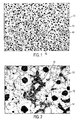
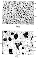
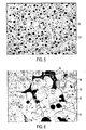
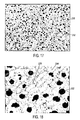
- Figs. 1 through 8 illustrate magnified images of each of the samples that have been etched by nital, a dilute mixture of nitric acid and alcohol.
- Fig. 1 illustrates, at 100X magnification, one example of a nital-etched microstructure of an alloy of known art.
- This first sample identified as the high-silicon molybdenum ductile iron above, was comprised, by weight, of 3.04% carbon, 3.94% silicon, 0.56% molybdenum, 0.39% manganese, 0.014% phosphorus, 0.006% sulfur, 0.039% magnesium, 0.072% nickel, and 0.015% niobium, the balance iron.
- UTS of this high-silicon molybdenum alloy was 590 MPa (85.4 KSI) the 0.2% yield strength was 450 MPa (65.1 KSI) and the elongation percentage was 18%.
- Fig. 2 illustrates, at 500X magnification, the microstructure shown in Fig. 1 .
- the sample illustrated in Figs. 1 and 2 shows typical ferritic grain structure (10) and spheroidal graphites (12). Dispersed throughout this alloy sample are structures (14) of pearlite.
- Pearlite is a mixture of ferrite and cementite which forms in the alloy as it cools. While the presence of pearlite is desirable in cast ferrite alloys where pearlite is used as a means of increasing the hardness of the alloy, it is also undesireable in applications where higher ductility is desired since its presence also reduces ductility.
- the alloy though harder, is also more prone to fracture, particularly at high temperatures.
- the use of molybdenum in the sample alloy in the amount specified tends to produce pearlite amount between 5% and 10%. Also dispersed throughout the sample are ill-defined gray areas (16) of intercellular complex carbides, which also adversely affect ductility.
- Fig . 3 illustrates, at 100X magnification, one example of a microstructure of an alloy which does not fall within the scope of the present invention which, by weight, was comprised of 3.08% carbon, 4.08% silicon, 0.03% molybdenum, 0.37% manganese, 0.009% phosphorus, 0.005% sulfur, 0.035% magnesium, 0.11 % nickel, and 0.46% niobium, the balance iron.
- This example is referred to as the "second sample” above and was identified above as a high-silicon niobium ductile iron.
- Fig. 4 illustrates, at 500X magnification, the microstructure shown in Fig. 3 .
- the high-silicon niobium sample illustrated in Figs. 3 and 4 shows largely ferritic grain structure (20) and spheroidal graphites (22). Dispersed throughout the sample are black structures (24) of pearlite. A shown, the use of niobium at 0.46% tends to reduce the pearlite amounts to less than 5%. Also dispersed throughout the sample are ill-defined gray areas (26) of intercellular complex carbides and smaller niobium carbide globules (28).
- Fi 5 illustrates, at 100X magnification another example of a microstructure of an alloy which does not fall within the scope of the present invention which, by weight, was comprised of 3.19% carbon, 3.92% silicon, 0.04% molybdenum, 0.40% manganese, 0.009% phosphorus, 0.005% sulfur, 0.055% magnesium, 0.0784% nickel, and 0.67% niobium, the balance iron.
- This example is referred to as the "third sample” above and was identified above as a high-silicon high-niobium ductile iron.
- Fig. 6 illustrates, at 500X magnification, the microstructure shown in Fig. 5 .
- the high-silicon high-niobium sample illustrated in Figs. 5 and 6 shows largely ferritic grain structure (30) and spheroidal graphites (32). Dispersed throughout the sample are black structures (34) of pearlite. A shown, the use of niobium at 0.67% tends to further reduce the pearlite amounts. Also dispersed throughout the sample are ill-defined gray areas (36) of intercellular complex carbides and smaller niobium carbide globules (38).
- Fig 7 illustrates, at 100X magnification, yet another example of a microstructure of an alloy which does not fall within the scope of the present invention which, by weight, was comprised of 3.36% carbon, 3.91 % silicon, 0.02% molybdenum, 0.32% manganese, 0.013% phosphorus, 0.008% sulfur, 0.042% magnesium, 0.04% nickel, and 0.94% niobium, the balance iron.
- This example is referred to as the "fourth sample” above and was identified above as a high-silicon ultra-high-niobium ductile iron At room temperature, the UTS of this alloy was 590 MPa (85.0 KSI) the 0.2% yield strength was 460 MPa (66.5 KSI) and the elongation percentage was 16%.
- FIG. 8 illustrates, at 500X magnification, the microstructure shown in Fig. 7 .
- the high-silicon ultra-high-niobium sample illustrated in Figs. 7 and 8 shows largely ferritic grain structure (40) and spheroidal graphites (42). Dispersed throughout the sample are black structures (44) of pearlite. A shown, the use of niobium at 0.94% tends to reduce the pearlite amounts even further. Also dispersed throughout the sample are niobium carbide globules (48). But note that there is no sign of intercellular complex carbides in this sample.
- the machining characteristics of the high-silicon niobium ductile iron of the present invention were superior to those of the high-silicon moly bdenum-alloy. Also, the high-silicon niobium ductile iron of the present invention provided considerably higher ductility and creep stress rupture properties up to 800°C than did the high-silicon molybdenum ductile iron.
- the samples of the high-silicon molybdenum, the high-silicon niobium, and the high-silicon high-niobium alloys were each tested for their respective UTS, 0.02% offset yield, elongation percentage and "reduction of area" percentage values at temperature increments of 100°C.
- the high-silicon ultra-high-niobium alloy was tested only at room temperature, as referred to above, and at 800°C, the extreme ends of this high temperature testing.
- Figs. 9 through 12 the performance characteristics of the first three samples are illustrated in graphical form based on test results measured in 100°C increments. Specifically, those include the 0.56% molybdenum alloy, the 0.46% niobium alloy and the 0.67 high-niobium alloy.
- Fig. 9 represents the UTS of those samples and Fig. 10 represents the 0.2% yield strength of each. Recall that these values represent the relative "strength" of the alloys.
- Fig. 11 represents the elongation percentage and .
- Fig. 12 represents the "reduction of area percentage” values, also measured in 100°C increments. These last two graphs illustrate the relative "ductility" of the respective alloys. It should also be mentioned here that the "reduction of area percentage” value is a measure of the relative area of the "neck" of the specimen at the point of fracture as compared to the area of the pre-stressed specimen.
- the values of the 0.56% molybdenum alloy (110) are shown plotted against those of the 0.46% niobium alloy (120) and the 0.67% high-niobium alloy (130).
- the "hardness" of the molybdenum alloy (110) is somewhat greater than that of either the niobium alloy (120) or the high-niobium alloy (130).
- the "ductility" of the molybdenum alloy (110) is substantially less than that of either the niobium allow (120) or the high-niobium alloy (130), particularly at higher temperatures.
- Normalizing is a type of heat treatment applicable to ferrous metals only. Normalization involves the austenitizing of the ductile iron casting, followed by cooling in air through a critical temperature. The casting is normalized by means of "soaking" the casting within a heated environment for a pre-determined period of time. A ductile iron casting is normalized in order to break down carbides, to increase strength, and to remove the internal stresses that are induced within the casting and which are brought about by the casting process itself.
- the average UTS of the molybdenum alloy was 560 MPa (81.3 KSI)
- the average UTS for the niobium alloy was 570 MPa (82.7 KSI) and for the high-niobium alloy was 570 MPa (82.8 KSI)
- the average 0.2% offset yield of the molybdenum alloy was 430 MPa (62.5 KSI).
- the 0.2% offset yield of the niobium alloy was 440 MPa (64.2 KSI) and of the high-niobium alloy was 445 MPa (64.5 KSI) Accordingly, the high temperature soaking resulted in the niobium addition alloys being slightly stronger at room temperature.
- the average elongation percentage of the molybdenum alloy was 17%.
- the average elongation percentage for the niobium alloy was 18% and for the high-niobium alloy was also 18%.
- the reduction of area percentage of the molybdenum alloy was 24%.
- the reduction of area percentage of the niobium alloy was 26% and of the high-niobium alloy was 25%. Accordingly, the high temperature soaking also resulted in the niobium addition alloys being slightly more ductile at room temperature.
- the average UTS of the molybdenum alloy was 40 MPa (5.8 KSI).
- the average UTS for the niobium alloy was 36 MPa (5.2 KSI) and for the high-niobium alloy was 39 MPa (5.7 KSI).
- the average 0.2% offset yield of the molybdenum alloy was 28 MPa (4.0 KSI).
- the 0.2% offset yield of the niobium alloy was 24 MPa (3.5 KSI) and of the high-niobium alloy was 26 MPa (3.8 KSI) Accordingly, the high temperature soaking resulted in the niobium addition alloys yielding slightly less strength at higher temperature than the molybdenum addition alloy.
- the average elongation percentage of the molybdenum alloy was 57%.
- the average elongation percentage for the niobium alloy was 65% and for the high-niobium alloy was 61 %.
- the reduction of area percentage of the molybdenum alloy was 60%.
- the reduction of area percentage of both the niobium and the high-niobium alloys was 63%. Accordingly, the high temperature soaking also resulted in the niobium addition alloys being significantly more ductile at high temperatures.
- Figs. 13 through 18 illustrate magnified images of each of the heat-soaked samples that have also been nital-etched. More specifically, Fig. 13 illustrates, at 100X magnification, the first sample of high-silicon molybdenum ductile iron. Fig. 14 illustrates, at 500X magnification, the microstructure shown in Fig. 13 . Both microstructures illustrated in Figs. 13 and 14 at 100X and 500X show basically ferritic grain structures (210) and spheroidal graphites (212) that are dispersed throughout the sample. Note also the presence of intercellular complex carbides (214), particularly in Fig. 14 .
- Fig. 15 illustrates, at 100X magnification, the heat-soaked high-silicon niobium ductile iron.
- Fig. 16 illustrates, at 500X magnification, the microstructure shown in Fig. 15 .
- the high-silicon niobium sample illustrated in Figs. 15 and 16 shows basically ferritic grain structures (220) and spheroidal graphites (222). Also dispersed throughout the sample are niobium carbide globules (228). Note the absence of intercellular complex carbides in this sample.
- Fig. 17 illustrates, at 100X magnification, the heak-soaked high-silicon high-niobium ductile iron.
- Fig. 18 illustrates, at 500X magnification, the microstructure shown in Fig. 17 .
- the high-silicon high-niobium sample illustrated in Figs. 17 and 18 shows basically ferritic grain structures (230) and spheroidal graphites (232). Also dispersed throughout the sample are niobium carbide globules (238). Note the absence of intercellular complex carbides in this sample as well.
- high-silicon niobium addition alloy of the present invention two specially designed melts were created.
- a turbocharger was selected as the test casting due to its affinity for cracks propagating through the divider wall and tongue area when run on an engine test at high temperature.
- Sample batches of high-silicon molybdenum alloy and high-silicon niobium allo were used.
- the high-silicon molybdenum alloy which does not fall within the scope of the invention, a chemical composition, by weight, of 3.12% carbon, 3.98% silicon, 0.57% molybdenum, 0.35% manganese, 0.012% phosphorus, 0.007% sulfur, 0.041% magnesium, 0.09% nickel, 0.01 % niobium and the balance iron.
- the high-silicon niobium alloy which does not fall within the scope of the invention, had a chemical composition, by weight, of 3.15% carbon, 4.17% silicon, 0.02% molybdenum, 0.32% manganese, 0.014% phosphorus, 0.009% sulfur, 0.039% magnesium, 0.14% nickel, 0.6% niobium, and the balance iron.
- the relative hardness of the high-silicon molybdenum alloy ranged between 217 BHN and 228 BHN.
- the high-silicon niobium alloy had a relative hardness of between 207 BHN and 228 BHN.
- Figs. 19 through 22 illustrate magnified images of each of the above-referenced samples that have also been nital-etched. More specifically, Fig. 19 illustrates, at 100X magnification, the first sample of the casting divider wall made with the high-silicon molybdenum ductile iron, with 0.57% molybdenum. Fig. 20 illustrates, at 500X magnification, the microstructure shown in Fig. 19 .
- the sample illustrated in Figs. 19 and 20 shows ferritic grain structure (310) and spheroidal graphites (312) along with well-defined black structures (314) of pearlite. Also dispersed throughout the sample are a larger number of ill-defined gray areas (316) of intercellular complex carbides.
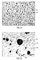
- Fig. 21 illustrates, at 100X magnification, the casting divider sample made of high-silicon niobium ductile iron, with 0.60% niobium.
- Fig. 22 illustrates, at 500X magnification, the microstructure shown in Fig. 21 .
- the high-silicon niobium sample illustrated in Figs. 21 and 22 shows largely ferritic grain structure (320) and spheroidal graphites (322) with very low percent, less than 2%, pearlite (324) with no sign of intercellular complex carbides.
- niobium carbide globules (328) dispersed throughout the sample, the presence of which is good because such globules (328) will not break down during useful application of the structure.
- niobium-add alloy As demonstrated above, testing of the niobium-add alloy proved that the alloy had a better microstructure containing very low, if any, pearlite and carbide content and that it had excellent ductility and creep rupture properties. It is known in the art that chromium added to an iron-based ductile alloy improves oxidation and corrosion resistance properties of the alloy. In view of that art, this inventor produced an ultra high silicon niobium and chromium alloy to determine whether those properties would be affected by the substitution of niobium for molybdenum in this type of alloy.
- the specification target that was used as a starting point for development of the ultra high silicon niobium and chromium alloy according to present invention specifies carbon in an amount of 2.8 to 2.9% by weight, silicon in an amount of 4.4 to 4.8% by weight, molybdenum in an amount of 0.05% by weight or less, niobium in an amount of 0.6 to 0.8% by weight, chromium in an amount of 0.75 to 0.9% by weight, manganese in an amount of 0.4% by weight or less, sulfur in an amount of 0.02% by weight or less, phosphorus in an amount of 0.04% by weight or less, nickel in an amount of 0.5% by weight or less, copper in an amount of 0.03 to 0.07% by weight, magnesium in an amount of 0.03 to 0.07% by weight or less, and the balance iron.
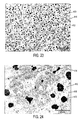
- Figs. 23 and 24 show magnified images of the-heat treated sample that has been nital-etched.
- the final chemistry of this sample was, by weight, 2.79% carbon, 4.67% silicon, 0.77% niobium, 0.87% chromium, 0.04% molybdenum, 0.34% manganese, 0.01% phosphorus, 0.01% sulfur, 0.03% magnesium, 0.08% nickel, and 0.05% copper, the balance iron.
- Fig. 23 illustrates the microstructure of this heat treated sample at 100X magnification.
- Fig. 24 illustrates, at 500X magnification, the microstructure shown in Fig. 23 .
- the sample illustrated in Figs. 23 and 24 shows typical ferritic grain structure (410) and spheroidal graphites (412). Dispersed throughout this alloy sample are chromium carbide structures (414) and niobium carbide globules (418). Note the complete absence of pearlite and intercellular complex carbides in this sample.
- FIG. 25 illustrates the microstructure of this heat treated sample at 100X magnification.
- Fig. 26 illustrates, at 500X magnification, the microstructure shown in Fig. 25.
- the sample illustrated in Figs. 25 and 26 again shows typical ferritic grain structure (420) and spheroidal graphites (422). Dispersed throughout this alloy sample are chromium carbide structures (422) and niobium carbide globules (428). Note the complete absence of pearlite and intercellular complex carbides in this sample.
- the reason that the creep rupture test and ductility of the alloy shows a much increased result when using niobium over molybdenum is because of the fundamental microstructure differences between the molybdenum and niobium additions.
- molybdenum tends to produce more pearlite amounts, those amount being between 5% and 10%.
- the niobium addition tends to produce much less than 5% pearlite in the microstructure.
- the molybdenum addition also tends to produce more intercellular complex carbides than the niobium addition.
- the reason for the occurrence of larger amounts of pearlite and intercellular complex carbides in the molybdenum addition is that after graphite nodule formation, the molybdenum tends to combine with the free carbon to produce those items.
- niobium combines with carbon and produces niobium carbides in a very fine globule shape throughout the microstructure.
- the levels of pearlite and intercellular complex carbides in the molybdenum addition result is increased hardness and reduced ductility of the alloy at room temperature and at high temperatures along with lower creep stress rupture test results as is evident from the test results obtained.
- the end result in the niobium addition alloy is a reduction in hardness and an increase in ductility at room temperature and at high temperature along with higher creep stress rupture test results, also evident from the data collected.
- the niobium-add alloy of the present invention also demonstrated enhanced performance properties when used in ultra high silicon chromium and ultra high silicon and ultra high chromium applications for corrosion and oxidation resistance.
Landscapes
- Chemical & Material Sciences (AREA)
- Engineering & Computer Science (AREA)
- Materials Engineering (AREA)
- Mechanical Engineering (AREA)
- Metallurgy (AREA)
- Organic Chemistry (AREA)
- Refinement Of Pig-Iron, Manufacture Of Cast Iron, And Steel Manufacture Other Than In Revolving Furnaces (AREA)
- Supercharger (AREA)
- Heat Treatment Of Steel (AREA)
Abstract
Claims (7)
- Alliage de fer ductile résistant à haute température amélioré comprenant :du carbone dans une quantité de 2,8 % à 2,9 % en poids,du silicium dans une quantité de 4,4 % à 4,8 % en poids,du niobium dans une quantité de 0,6 % à 0,8 % en poids,du molybdène dans une quantité de 0,05 % en poids ou moins,du manganèse dans une quantité de 0,4 % en poids ou moins,du soufre dans une quantité de 0,02 % en poids ou moins,du phosphore dans une quantité de 0,04 % en poids ou moins,du nickel dans une quantité de 0,5 % en poids ou moinsdu chrome dans une quantité de 0,75 % à 0,9 % en poids ou moins,du cuivre dans une quantité de 0,03 % à 0,07 % en poids,du magnésium dans une quantité de 0,03 % à 0,07 % en poids ou moins, et le reste étant du fer.
- Procédé de production d'un alliage de fer ductile résistant à haute température amélioré selon la revendication 1, comprenant les étapes consistant à :fournir du carbone dans une quantité de 2,8 % à 2,9 % en poids,fournir du silicium dans une quantité de 4,4 % à 4,8 % en poids,fournir du niobium dans une quantité de 0,6 % à 0,8 % en poids,fournir du molybdène dans une quantité de 0,05 % en poids ou moins,fournir du manganèse dans une quantité de 0,4 % en poids ou moins,fournir du soufre dans une quantité de 0,02 % en poids ou moins,fournir du phosphore dans une quantité de 0,04 % en poids ou moins,fournir du nickel dans une quantité de 0,5 % en poids ou moinsfournir du chrome dans une quantité de 0,75 % à 0,9 % en poids ou moins,fournir du cuivre dans une quantité de 0,03 % à 0,7 % en poids ou moins,fournir du magnésium dans une quantité de 0,03 % à 0,07 % en poids ou moins,fournir l'équilibre en fer,combiner les éléments,faire fondre les éléments combinés, etrefroidir à l'air l'alliage sous la forme d'un produit final.
- Alliage de fer ductile résistant à haute température amélioré selon la revendication 1, ou procédé de production d'un alliage de fer ductile résistant à haute température amélioré selon la revendication 2, où la résistance à la traction maximale résultante de l'alliage est supérieure à 500 MPa (75 000 psi), ou 75 KSI, à température ambiante.
- Alliage de fer ductile résistant à haute température amélioré selon la revendication 1, ou procédé de production d'un alliage de fer ductile résistant à haute température amélioré selon la revendication 2, où la dureté limite à 0,2 % résultante de l'alliage est supérieure à 400 MPa (60 000 psi), ou 60 KSI, à température ambiante.
- Alliage de fer ductile résistant à haute température amélioré selon la revendication 1, ou procédé de production d'un alliage de fer ductile résistant à haute température amélioré selon la revendication 2, où la dureté résultante de l'alliage selon le nombre de dureté de Brinell est comprise entre 187 BHN et 241 BHN à température ambiante.
- Alliage de fer ductile résistant à haute température amélioré selon la revendication 1, ou procédé de production d'un alliage de fer ductile résistant à haute température amélioré selon la revendication 2, où le pourcentage de ductilité d'élongation résultant dépasse 10 % à température ambiante.
- Procédé de production d'un alliage de fer ductile résistant à haute température amélioré selon la revendication 2, comprenant, avant l'étape de refroidissement à l'air, l'étape de normalisation de l'alliage par maintien à température du produit final à 750°C pendant 200 heures.
Applications Claiming Priority (1)
| Application Number | Priority Date | Filing Date | Title |
|---|---|---|---|
| PCT/US2005/032975 WO2007040464A1 (fr) | 2005-09-15 | 2005-09-15 | Alliage de moulage a forte teneur en silicium niobium et processus pour produire celui-ci |
Publications (3)
| Publication Number | Publication Date |
|---|---|
| EP1931810A1 EP1931810A1 (fr) | 2008-06-18 |
| EP1931810A4 EP1931810A4 (fr) | 2009-09-09 |
| EP1931810B1 true EP1931810B1 (fr) | 2011-11-02 |
Family
ID=37906417
Family Applications (1)
| Application Number | Title | Priority Date | Filing Date |
|---|---|---|---|
| EP05858417A Expired - Lifetime EP1931810B1 (fr) | 2005-09-15 | 2005-09-15 | Alliage de moulage a forte teneur en silicium niobium et processus pour produire celui-ci |
Country Status (5)
| Country | Link |
|---|---|
| US (1) | US8012410B2 (fr) |
| EP (1) | EP1931810B1 (fr) |
| JP (1) | JP4904357B2 (fr) |
| CN (1) | CN101300368B (fr) |
| WO (1) | WO2007040464A1 (fr) |
Families Citing this family (14)
| Publication number | Priority date | Publication date | Assignee | Title |
|---|---|---|---|---|
| US8328703B2 (en) * | 2009-05-29 | 2012-12-11 | Acos Villares S.A. | Rolling mill cast roll |
| CN101603143B (zh) * | 2009-07-23 | 2010-11-03 | 芜湖市金贸流体科技股份有限公司 | 耐高温球墨铸铁管件及其生产方法 |
| CN101818298B (zh) * | 2010-05-20 | 2012-03-28 | 什邡市明日宇航工业股份有限公司 | 一种耐蚀中硅钼镍钴球墨铸铁合金 |
| JP5712531B2 (ja) * | 2010-09-02 | 2015-05-07 | Jfeスチール株式会社 | 耐摩耗性に優れた球状黒鉛鋳鉄品 |
| EP2511394B1 (fr) * | 2011-04-15 | 2015-05-27 | Siemens Aktiengesellschaft | Fonte dotée de niobium et composant |
| CN102534355A (zh) * | 2012-01-18 | 2012-07-04 | 湖南正圆动力配件有限公司 | 含铌富硅球墨铸铁、该球墨铸铁的制备方法及用球墨铸铁制成的活塞环 |
| CN104342594A (zh) * | 2014-12-02 | 2015-02-11 | 江苏金洋机械有限公司 | 一种用于制备高铁扣件用铁垫板的合金 |
| US10787726B2 (en) * | 2016-04-29 | 2020-09-29 | General Electric Company | Ductile iron composition and process of forming a ductile iron component |
| CN106011609B (zh) * | 2016-07-29 | 2018-03-02 | 西峡县内燃机进排气管有限责任公司 | 一种中硅钼铌球墨铸铁材料及其制备方法 |
| CN107354369B (zh) * | 2017-06-20 | 2019-04-16 | 哈尔滨汽轮机厂有限责任公司 | 一种在500℃高温下使用的含钼球墨铸铁及其制备方法 |
| CN107475612A (zh) * | 2017-08-29 | 2017-12-15 | 马鞍山市三川机械制造有限公司 | 一种用于内燃机气缸体的合金材料 |
| CN109402496A (zh) * | 2018-11-28 | 2019-03-01 | 精诚工科汽车系统有限公司 | 具有均匀壁厚的球墨铸铁铸件中合金元素添加量的确定方法与球墨铸铁铸件及其铸造和模具 |
| KR102286542B1 (ko) | 2019-12-10 | 2021-08-05 | 주식회사 진흥주물 | 고강도 및 고인성을 갖는 페라이트계 주철합금 |
| KR20210157665A (ko) | 2020-06-22 | 2021-12-29 | 주식회사 진흥주물 | 인장강도 600MPa급 및 연신율 10% 이상의 페라이트계 주철합금 |
Family Cites Families (19)
| Publication number | Priority date | Publication date | Assignee | Title |
|---|---|---|---|---|
| DE1482724U (fr) | ||||
| DE1500766U (fr) | ||||
| SE335624B (fr) | 1967-01-13 | 1971-06-01 | Trafik Ab Graengesbergs Oxeloe | |
| US3893873A (en) | 1973-05-07 | 1975-07-08 | Nippon Kinzoku Co Ltd | Method for manufacturing spheroidal graphite cast iron |
| DE3147461C2 (de) * | 1981-12-01 | 1983-10-13 | Goetze Ag, 5093 Burscheid | Verschleißfeste Gußeisenlegierung hoher Festigkeit mit sphärolithischer Graphitausscheidung, ihr Herstellungsverfahren und ihre Verwendung |
| JPS61157655A (ja) | 1984-12-28 | 1986-07-17 | Daido Steel Co Ltd | 鋳造工具 |
| JPS62142745A (ja) * | 1985-12-17 | 1987-06-26 | Toyota Motor Corp | 耐熱性球状黒鉛鋳鉄 |
| JPS6372850A (ja) | 1986-09-12 | 1988-04-02 | Toyota Motor Corp | 耐摩耗性及び耐酸化性に優れた球状黒鉛鋳鉄 |
| BE1006356A3 (fr) | 1991-12-19 | 1994-08-02 | Fond Marichal Ketin & Cie Sa D | Cylindre de travail bimetallique pour le laminage a chaud de bandes d'acier. |
| US5330705A (en) | 1993-06-04 | 1994-07-19 | Carondelet Foundry Company | Heat resistant alloys |
| ES2201186T5 (es) | 1995-06-06 | 2007-03-01 | Akers International Ab | Rodillo de temple superficial indefinido de fundicion de hierro, producido por la adicion de niobio. |
| DE19545611C1 (de) | 1995-12-07 | 1997-03-13 | Daimler Benz Ag | Optimierte Lamellen-Graugußlegierung für Bremsscheiben von Nutzfahrzeug |
| US6669790B1 (en) | 1997-05-16 | 2003-12-30 | Climax Research Services, Inc. | Iron-based casting alloy |
| US6436338B1 (en) | 1999-06-04 | 2002-08-20 | L. E. Jones Company | Iron-based alloy for internal combustion engine valve seat inserts |
| US6508981B1 (en) | 2001-05-24 | 2003-01-21 | Wescast Industries, Inc. | High temperature oxidation resistant ductile iron |
| KR100762151B1 (ko) | 2001-10-31 | 2007-10-01 | 제이에프이 스틸 가부시키가이샤 | 딥드로잉성 및 내이차가공취성이 우수한 페라이트계스테인리스강판 및 그 제조방법 |
| JP2003221639A (ja) | 2002-01-31 | 2003-08-08 | Aisin Takaoka Ltd | タービンハウジング一体型排気マニホルド及びその製造方法 |
| DE502004006994D1 (de) | 2003-11-20 | 2008-06-12 | Borgwarner Inc | Hitzebeständige Superlegierung und ihre Verwendung |
| US20080274005A1 (en) | 2005-05-05 | 2008-11-06 | Wescast Industries, Inc. | Cast Iron With Improved High Temperature Properties |
-
2005
- 2005-09-15 JP JP2008531066A patent/JP4904357B2/ja not_active Expired - Lifetime
- 2005-09-15 US US12/066,974 patent/US8012410B2/en active Active
- 2005-09-15 WO PCT/US2005/032975 patent/WO2007040464A1/fr not_active Ceased
- 2005-09-15 EP EP05858417A patent/EP1931810B1/fr not_active Expired - Lifetime
- 2005-09-15 CN CN2005800515933A patent/CN101300368B/zh not_active Expired - Lifetime
Also Published As
| Publication number | Publication date |
|---|---|
| US20080260568A1 (en) | 2008-10-23 |
| WO2007040464A1 (fr) | 2007-04-12 |
| US8012410B2 (en) | 2011-09-06 |
| CN101300368B (zh) | 2011-08-31 |
| JP4904357B2 (ja) | 2012-03-28 |
| EP1931810A1 (fr) | 2008-06-18 |
| JP2009509035A (ja) | 2009-03-05 |
| CN101300368A (zh) | 2008-11-05 |
| EP1931810A4 (fr) | 2009-09-09 |
Similar Documents
| Publication | Publication Date | Title |
|---|---|---|
| EP1931810B1 (fr) | Alliage de moulage a forte teneur en silicium niobium et processus pour produire celui-ci | |
| US10941470B2 (en) | Cr-Mn-N austenitic heat-resistant steel and a method for manufacturing the same | |
| CA2580933A1 (fr) | Alliage d'acier inoxydable austenitique coule resistant a la chaleur et a la corrosion et ayant une meilleure resistance a haute temperature | |
| EP2354265A1 (fr) | Fonte ductile austénitique | |
| KR101799844B1 (ko) | 우수한 탕류성, 내가스 결함성, 인성 및 피삭성을 가지는 페라이트계 내열 주강, 및 이들로 이루어지는 배기계 부품 | |
| KR20180052111A (ko) | 지열 발전 터빈 로터용 저합금강 및 지열 발전 터빈 로터용 저합금 물질, 및 이들의 제조 방법 | |
| WO2010097673A1 (fr) | Fonte ferritique à graphite sphéroïdal | |
| EP3399063A1 (fr) | Acier cémenté, élément cémenté et procédé destiné à la production d'acier cémenté | |
| JP2009509035A5 (fr) | ||
| KR102453685B1 (ko) | 열피로 특성이 우수한 오스테나이트계 내열 주강 및 그것으로 이루어지는 배기계 부품 | |
| EP1865082A1 (fr) | Font à haut resistance à l'oxydation en temps elevés. | |
| JPS624855A (ja) | ステンレス鋼鋳造合金およびその製造方法 | |
| Chao et al. | Effect of Nb/V alloying on the microstructure and mechanical properties of SiMo ductile iron | |
| JP2000273570A (ja) | 圧力容器用鋳鋼材及びそれを用いる圧力容器の製造方法 | |
| JPH0987796A (ja) | 耐熱球状黒鉛鋳鉄 | |
| Jogdand et al. | A modified AISI 310 steel family: Microstructure engineering for high-temperature load-bearing applications | |
| JP2006169635A (ja) | ダクタイル鋳鉄合金 | |
| US4528045A (en) | Heat-resisting spheroidal graphite cast iron | |
| US11667995B2 (en) | Cast iron alloy for automotive engine applications with superior high temperature oxidation properties | |
| EP3805418A1 (fr) | Matériau d'acier pour pistons en acier | |
| JPH0734204A (ja) | フェライト系耐熱鋳鋼およびその製造方法 | |
| Stefanescu | Mechanical properties of ductile irons | |
| Shingledecker et al. | CF8C plus: a new high temperature austenitic casting alloy for advanced power systems | |
| Yoo et al. | Effects of Cr Reduction on High-Temperature Strength of High-Ni Austenitic Cast Steels Used for High-Performance Turbo-chargers | |
| JP5099978B2 (ja) | 高強度細線及びその製造方法 |
Legal Events
| Date | Code | Title | Description |
|---|---|---|---|
| PUAI | Public reference made under article 153(3) epc to a published international application that has entered the european phase |
Free format text: ORIGINAL CODE: 0009012 |
|
| 17P | Request for examination filed |
Effective date: 20080328 |
|
| AK | Designated contracting states |
Kind code of ref document: A1 Designated state(s): DE FR GB IT |
|
| RBV | Designated contracting states (corrected) |
Designated state(s): DE FR GB IT |
|
| RBV | Designated contracting states (corrected) |
Designated state(s): DE FR GB IT |
|
| A4 | Supplementary search report drawn up and despatched |
Effective date: 20090806 |
|
| 17Q | First examination report despatched |
Effective date: 20091109 |
|
| RAP1 | Party data changed (applicant data changed or rights of an application transferred) |
Owner name: GREDE LLC |
|
| GRAP | Despatch of communication of intention to grant a patent |
Free format text: ORIGINAL CODE: EPIDOSNIGR1 |
|
| DAX | Request for extension of the european patent (deleted) | ||
| GRAS | Grant fee paid |
Free format text: ORIGINAL CODE: EPIDOSNIGR3 |
|
| GRAA | (expected) grant |
Free format text: ORIGINAL CODE: 0009210 |
|
| AK | Designated contracting states |
Kind code of ref document: B1 Designated state(s): DE FR GB IT |
|
| REG | Reference to a national code |
Ref country code: GB Ref legal event code: FG4D |
|
| REG | Reference to a national code |
Ref country code: DE Ref legal event code: R096 Ref document number: 602005031035 Country of ref document: DE Effective date: 20111229 |
|
| RAP2 | Party data changed (patent owner data changed or rights of a patent transferred) |
Owner name: GREDE LLC |
|
| REG | Reference to a national code |
Ref country code: DE Ref legal event code: R081 Ref document number: 602005031035 Country of ref document: DE Owner name: GREDE LLC, US Free format text: FORMER OWNER: GREDE LLC, NOVI, US Effective date: 20120130 Ref country code: DE Ref legal event code: R081 Ref document number: 602005031035 Country of ref document: DE Owner name: GREDE LLC, SOUTHFIELD, US Free format text: FORMER OWNER: GREDE LLC, NOVI, MICH., US Effective date: 20120130 |
|
| PG25 | Lapsed in a contracting state [announced via postgrant information from national office to epo] |
Ref country code: IT Free format text: LAPSE BECAUSE OF FAILURE TO SUBMIT A TRANSLATION OF THE DESCRIPTION OR TO PAY THE FEE WITHIN THE PRESCRIBED TIME-LIMIT Effective date: 20111102 |
|
| PLBE | No opposition filed within time limit |
Free format text: ORIGINAL CODE: 0009261 |
|
| STAA | Information on the status of an ep patent application or granted ep patent |
Free format text: STATUS: NO OPPOSITION FILED WITHIN TIME LIMIT |
|
| 26N | No opposition filed |
Effective date: 20120803 |
|
| REG | Reference to a national code |
Ref country code: DE Ref legal event code: R097 Ref document number: 602005031035 Country of ref document: DE Effective date: 20120803 |
|
| REG | Reference to a national code |
Ref country code: FR Ref legal event code: PLFP Year of fee payment: 11 |
|
| REG | Reference to a national code |
Ref country code: FR Ref legal event code: PLFP Year of fee payment: 12 |
|
| REG | Reference to a national code |
Ref country code: FR Ref legal event code: PLFP Year of fee payment: 13 |
|
| REG | Reference to a national code |
Ref country code: FR Ref legal event code: PLFP Year of fee payment: 14 |
|
| PGFP | Annual fee paid to national office [announced via postgrant information from national office to epo] |
Ref country code: DE Payment date: 20240927 Year of fee payment: 20 |
|
| PGFP | Annual fee paid to national office [announced via postgrant information from national office to epo] |
Ref country code: GB Payment date: 20240927 Year of fee payment: 20 |
|
| PGFP | Annual fee paid to national office [announced via postgrant information from national office to epo] |
Ref country code: FR Payment date: 20240925 Year of fee payment: 20 |
|
| REG | Reference to a national code |
Ref country code: DE Ref legal event code: R071 Ref document number: 602005031035 Country of ref document: DE |
|
| REG | Reference to a national code |
Ref country code: GB Ref legal event code: PE20 Expiry date: 20250914 |