EP1932440B1 - Amortisseur de coussin de protection, coussin de protection et vêtements de protection l'utilisant - Google Patents
Amortisseur de coussin de protection, coussin de protection et vêtements de protection l'utilisant Download PDFInfo
- Publication number
- EP1932440B1 EP1932440B1 EP06766764.2A EP06766764A EP1932440B1 EP 1932440 B1 EP1932440 B1 EP 1932440B1 EP 06766764 A EP06766764 A EP 06766764A EP 1932440 B1 EP1932440 B1 EP 1932440B1
- Authority
- EP
- European Patent Office
- Prior art keywords
- shock
- protective pad
- protective
- pad
- absorbents
- Prior art date
- Legal status (The legal status is an assumption and is not a legal conclusion. Google has not performed a legal analysis and makes no representation as to the accuracy of the status listed.)
- Not-in-force
Links
- 230000035939 shock Effects 0.000 title claims description 119
- 230000001681 protective effect Effects 0.000 title claims description 78
- 230000002745 absorbent Effects 0.000 title claims description 56
- 239000002250 absorbent Substances 0.000 title claims description 56
- 239000002184 metal Substances 0.000 claims description 15
- 210000000689 upper leg Anatomy 0.000 claims description 13
- 230000035699 permeability Effects 0.000 claims description 9
- 239000000758 substrate Substances 0.000 claims description 9
- 239000006260 foam Substances 0.000 claims description 7
- 239000002984 plastic foam Substances 0.000 claims description 4
- 238000009958 sewing Methods 0.000 claims description 4
- JOYRKODLDBILNP-UHFFFAOYSA-N Ethyl urethane Chemical compound CCOC(N)=O JOYRKODLDBILNP-UHFFFAOYSA-N 0.000 claims description 3
- 230000002093 peripheral effect Effects 0.000 description 5
- 208000027418 Wounds and injury Diseases 0.000 description 4
- 239000004744 fabric Substances 0.000 description 4
- 230000006378 damage Effects 0.000 description 3
- 230000000694 effects Effects 0.000 description 3
- 210000000988 bone and bone Anatomy 0.000 description 2
- 229920000642 polymer Polymers 0.000 description 2
- 210000001694 thigh bone Anatomy 0.000 description 2
- 238000003466 welding Methods 0.000 description 2
- 229920000742 Cotton Polymers 0.000 description 1
- 208000001132 Osteoporosis Diseases 0.000 description 1
- 239000004698 Polyethylene Substances 0.000 description 1
- 239000006096 absorbing agent Substances 0.000 description 1
- NIXOWILDQLNWCW-UHFFFAOYSA-N acrylic acid group Chemical group C(C=C)(=O)O NIXOWILDQLNWCW-UHFFFAOYSA-N 0.000 description 1
- 238000010586 diagram Methods 0.000 description 1
- 238000006073 displacement reaction Methods 0.000 description 1
- 230000017525 heat dissipation Effects 0.000 description 1
- 208000014674 injury Diseases 0.000 description 1
- 210000003127 knee Anatomy 0.000 description 1
- -1 polyethylene Polymers 0.000 description 1
- 229920000573 polyethylene Polymers 0.000 description 1
- 230000005855 radiation Effects 0.000 description 1
Images



Classifications
-
- A—HUMAN NECESSITIES
- A41—WEARING APPAREL
- A41D—OUTERWEAR; PROTECTIVE GARMENTS; ACCESSORIES
- A41D13/00—Professional, industrial or sporting protective garments, e.g. surgeons' gowns or garments protecting against blows or punches
- A41D13/05—Professional, industrial or sporting protective garments, e.g. surgeons' gowns or garments protecting against blows or punches protecting only a particular body part
- A41D13/0506—Hip
-
- A—HUMAN NECESSITIES
- A41—WEARING APPAREL
- A41D—OUTERWEAR; PROTECTIVE GARMENTS; ACCESSORIES
- A41D31/00—Materials specially adapted for outerwear
- A41D31/04—Materials specially adapted for outerwear characterised by special function or use
- A41D31/28—Shock absorbing
- A41D31/285—Shock absorbing using layered materials
Definitions
- This invention relates to a shock absorbent and a protective pad and protective clothes using the shock absorbent for protecting physical parts such as the haunch bone of lumbar part and the thigh bone of femur part from an external shock imparted thereto in a fall or the like.
- the shock absorbent for a protective pad of this kind is used for protecting the lumbar part against damage caused by a shock brought about in a fall or by an accident or sports events or other causes. Specifically, an old person or a person with osteoporosis or one who is at risk of the condition is susceptible to injury the lumbar part when accidentally falling.
- a protective pad for preventing damage to the lumbar part due to falling is formed integrally of a first layer of high density closed-cell polymer foam, a second layer of low density closed-cell polymer foam and at least one resilient energy absorbing insert embedded within the layers, so as to ensure relatively lightweight properties and acquire high impact resistance.
- the aforementioned protective pad can absorb a shock or impact when undergoing the shock throughout the whole area of the pad, but the conventional protective pad has disadvantages such that the shock caused to a part of the outer surface of the pad cannot sufficiently be absorbed.
- a protective pad capable of varying an area coming into contact with the lumbar part in accordance with the physical constitution of a user.
- a plurality of protective pads of unequal sizes should be prepared uneconomically.
- the present invention seeks primarily to provide a means capable of securely protecting physical parts such as the lumbar part and femur part from a shock even imparted intensively to a narrow area of the physical part to be protected, and secondarily to provide a shock absorbent and a protective pad and protective clothes using the shock absorbent, which can be brought into close contact with the physical part to be protected while improving air permeability around the physical part covered with the protective pad or clothes and vary the area contacting with the physical part to be protected.
- a shock absorbent according to the invention is used for a protective pad for protecting physical parts such as the lumbar part and femur part from an external shock exerted thereto and featured by embedding a shock dispersing member in a shock absorbing member for absorbing the external shock.
- the shock absorbent for a protective pad according to the invention is featured in that the shock dispersing member is formed by entwining two metal wires shifted laterally into coils and squashing the coils into a flat shape in whole so as to define contact parts overlapping each other and hollow parts formed by spreading the wire coils.
- the means according to the invention mentioned in Claim 1 can securely protect the physical parts such as the lumbar part and femur part even when exerting the shock intensively to a narrow area. That is, the external shock imparted to a large area is absorbed by the shock absorbing member, while the external shock imparted intensively to a narrow area is absorbed by the shock dispersing member, so that the physical parts such as the lumbar part and femur part can be securely protected.
- the shock dispersing member can be flexibly deformed with the shock absorbing member, so that the physical parts such as the lumbar part and femur part can be securely protected.
- the shock absorbent of the invention can be brought into close contact with the physical part to be protected.
- the weight per unit area of the shock absorbent of the invention can be reduced, consequently to reduce the weight of the protective pad and lessening a physical burden on a user in wearing the protective pad.
- the shock absorbent for a protective pad as set forth in Claim 2 is featured by having air vent holes bored from the front through the back of the shock absorbing member.
- the invention set forth in Claim 2 can improve air permeability by means of the air vent holes in the shock absorbing member.
- the shock absorbent for a protective pad as set forth in Claim 3 is featured in that the shock absorbing member is formed in a trilaminar structure in which cushioning members having different repulsive coefficients are stuck to both surfaces of a substrate having an accommodating hole analogous to the outline of the shock dispersing member.
- the invention set forth in Claim 3 can better absorb the shock exerted to the physical parts to be protected such as the lumbar part and femur part.
- the shock absorbent for a protective pad as set forth in Claim 4 is featured in that one of the two cushioning members on the side of the physical part to be protected is formed of plastic foam having air permeability such as highly foamable and low rebound urethane foam.
- the invention set forth in Claim 4 can better absorb the shock exerted to the physical parts to be protected and further improve air permeability
- the protective pad of the invention is featured in that the shock absorbents mentioned in any of the preceding claims are arranged densely so as to tolerate relative inclinations of the shock absorbents According to the invention set forth in Claim 5, the protective pad of the invention can be brought into close contact with the physical part to be protected and easily vary the contact area with the physical part by altering the number of the shock absorbents for the protective pad.
- the protective pad of the invention is featured in that the shock absorbents mentioned in Claim 5 are formed of polygonal plates having the same shape and same size and arranged so as to have the side walls being proximately opposite to one another.
- the invention mentioned in Claim 6 facilitates to arrange the shock absorbents densely.
- the protective pad mentioned in Claim 5 of the invention is featured by containing the shock absorbent in an outer covering having air permeability and sewing up the outer covering.7
- the invention mentioned in Claim 7 can bring the protective pad into close contact with the physical part to be protected and vary the contact area of the protective pad to the physical part to be protected.
- the outer covering containing the shock absorbent is sewed up, thereby to diminish humidity.
- protective clothes according to the invention is featured in that a pad containing bag for containing the protective pad mentionned in any of Claims 5 to 7 is formed so as to place the protective pad opposite to the physical part to be protected.
- the protective pad of the invention can easily be attached in position opposite to the physical part to be protected only by wearing the protective clothes without using any other accessories.
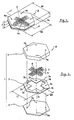
- FIG 1 is a perspective view of a shock absorbent for a protective pad according to one embodiment of the present invention
- FIG 2 is an exploded perspective view of the shock absorbent
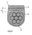
- FIG 3 is a cross sectional view taken along line I-I in FIG 1
- FIG 4 is a cross sectional view taken along line II-II in FIG 3 .
- shock absorbent A for the protective pad (hereinafter simply referred to as "shock absorbent") in one embodiment according to the present invention is applied for the protective pad, which will be described in detail later.
- the shock absorbent has a shock dispersing member 2 embedded in a shock absorbing member 1 for absorbing the external shock.
- the "absorbing of a shock” in this invention means low rebound, which has the property of specifically absorbing the external shock imparted to a large area throughout the outer surface of the shock absorbent A.
- the "dispersing of a shock” means a phenomenon in which a shock imparted intensively to a narrow area such as a part of the shock absorbent A is dispersed, that is, the shock power exerted is reduced per unit area.
- the shock absorbing member 1 is formed in a trilaminar structure in which cushioning members 4 and 5 having different repulsive coefficients are stuck to both surfaces of a substrate 3 and made of a regular hexagonal plate having a side wall distance W1 of about 45 mm, an apex distance W2 of about 52 mm, and a thickness t of about 11 mm.
- the shock absorbing member 1 is not limited to the hexagonal shape as illustrated in the embodiment and may be formed in a shape of convex polygon or concave polygon or any other heteromorphic shapes. Alternatively, it may be shaped in not only a polygon but also a perfect circle or ellipse.
- the substrate 3 is made of acrylic foam having a thickness of about 1 mm and has an accommodating hole 3a in the center and circular air vent holes 3c in four peripheral parts.
- the accommodating hole 3a is formed by intersecting crosswise slits 3b each having a width W of about 10 mm and a length L1 of 36 mm.
- the accommodating hole 3a serves to keep the shock dispersing member 2 in position relative to the substrate, which will be presented in detail later.
- the cushioning member 4 is formed of plastic foam such as highly foamable and low rebound urethane foam, which has a thickness of about 7 mm and air permeability.
- the cushioning member 4 is arranged so as to be opposite to a physical part (not shown) to be protected.
- the cushioning member has the air vent hole 4a positioned opposite to the air vent hole 3c in the substrate 3.
- the cushioning member 5 is formed of integrally of plastic foam such as closed-cell polyethylene foam, which has a thickness of about 3 mm and a circular air vent hole 5a positioned opposite to the air vent hole 3c in the substrate 3.
- FIG 5 is an enlarged front view of the shock dispersing member 2
- FIG 6 shows details of a coil constituting the shock dispersing member 2, in which (a) is an enlarged front view thereof, and (b) is a side view along line III-III in (a).
- the shock dispersing member 2 is formed by combining cruciately metal coils 6 each made of, for example, a SUS 304 wire having a wire diameter of about 0.6 mm, length of about 37 mm and width of about 10.
- the intersecting points 6c of the metal wire coils are connected by, for instance, spot welding.
- the coils 6 are formed by entwining in opposite directions two metal wires 6a and 6b into coils, shifting the coils laterally so as to define contact parts ⁇ overlapping each other and hollow parts ⁇ formed by spreading the wire coils and squashing the coils into a flat shape in whole.
- the "flat shape in whole” means flattening of the coils 6 and forming of flattened portions on the metal wires 6a and 6b.
- the flattened portions on the metal wires 6a and 6b are depicted in FIG 6 . However, only the coil 6 may be made flat without forming the flattened portions on the metal wires 6a and 6b.
- the metal wire 6a wound sinistrorsely and the metal wire 6b wound dextrorsely are intervolved with lateral shift of a crosswise length el and a longitudinal length e2.
- the shock dispersing member 2 having the closely-spaced metal wires 6a and 6b wound in opposite directions as described above has high thermal conductivity and high heat dissipation performance. Since the metal wires 6a and 6b are entwined to increase strength, the shock dispersing member 2 per se can be stabilized in its configuration and prevented from unbending when it is pressure-welded. Besides, the shock dispersing member is made flat to provide flexibility for the substrate 3 and cushioning members 4 and 5 when being deformed. That is, even when the shock dispersing member is embedded in the shock absorbing member 1, it can be flexibly deformed with the shock absorbing member 1, consequently to provide better wear comfort.
- the shock absorbent of the invention can be reduced in weight per unit area relative to a flat plate of the same size, consequently to attain lighter shock absorber.
- the hollow parts ⁇ formed between the metal wires 6a and 6b serve as ventilating means for permitting flow of air, thus to accelerate outgoing radiation.
- FIG 7 is a front view of the protective pad of the invention
- FIG 8 is a cross sectional view taken along line VI-VI in FIG 7 .
- the protective pad B according to the preferred embodiment of the invention is used for protecting the physical part such as the lumbar part and femur part from an external shock.
- the protective pad is formed by placing the polygonal shock absorbents of the same shape and size in the state of being proximately opposite to one another so as to assure a prescribed contact area covering the physical part to be protected such as the lumbar part and femur part and contained in an outer covering 7.
- the "physical part” is not limited only to the lumbar part and femur part as exemplified above, but has an implication further including the shoulder, arm, head, knee, chest and other body parts.
- the protective pad B employs seven shock absorbents A as mentioned above.
- the shock absorbents A are arranged so as to have the side walls A' being proximately opposite to the side walls A' of the adjacent shock absorbents A.
- the protective pad thus formed is placed between two air-permeable fabric cloths 7a made of cotton or the like and enclosed by sewing the cloths.
- proximately opposite implies not only the state of keeping distance between the side walls A' of the shock absorbents A, but also the state of bringing the shock absorbents into contact with each other through the outer covering 7.
- the number of the shock absorbents A is not limited to seven as in this embodiment, but may be adjusted so that the resultant protective pad has a prescribed size so as to adequately cover the physical parts to be protected such as the lumbar part and femur part.
- the outer covering 7 is sewed along the peripheral edge between the side walls of the adjacent protective pads B, which is shown by seam lines 8, 9 and 10 in the drawing.
- the shock absorbents A Since the adjacent shock absorbents A keep the prescribed distance between the side walls thereof and the peripheral edges between the side walls of the shock absorbents A are sewed, the shock absorbents A for the protective pad can steadily be secured relative to the outer covering 7 while tolerating relative inclinations of the shock absorbents, which are caused due to relative displacement of the shock absorbents A to the curved surface of the physical part to be protected. As a result, the shock absorbents A can be fitted closely to the physical part to be protected to improve wearability.
- the protective pads formed in the same polygonal shape of the same size are proximately arranged so as to cover the prescribed area of the physical part in the aforementioned embodiment as one example, the protective pads having different sizes may be densely arranged close to one another.
- FIG 9 is a front view of a pad containing bag of the invention
- FIG 10 is an explanatory diagram showing a wearing state of protective clothes of the invention.
- the protective clothes 10 according to the preferred embodiment of the present invention are provided on their back surfaces to be fitted to the lumbar part (physical part to be protected) with pad containing bags 11 for accommodating the aforementioned protective pads B, as shown in FIG 10 .
- the pad containing bag 11 has a substantially elongate size enough to accommodate the protective pad B and is formed of mesh fabrics having high air permeability.
- the pad containing bag is sewed to the back of the underclothing 12 along the peripheral edges of the upper element 11a and lower element 11b of mesh fabrics, which are superposed by a prescribed width L2.
- a prescribed width L2 By sewing the peripheral edges of the mesh fabrics to the back of the underwear 12 width in the state of bringing the lower side of the upper element 11 a into contact with the upper side of the lower element 11b by the prescribed seam, an opening for putting the protective pad B into the bag is formed.
- the protective pads B when wearing the protective clothes formed by containing the protective pads B in the pad containing bags 11, the protective pads B can be suitably placed in position opposite to the lumbar part.
- the shock absorbents A of the protective pads B opposite to the lumbar part can come in close contact with the lumbar part with relative inclination along the curved surface of the lumbar part in whole, so that the protective clothes can be comfortable to wear and protect steadily the lumbar part.
- the present invention is not to be considered limited to what is described above and shown in the drawings, but may be modified as specified below.
- the shock dispersing member may be made of a single coil or a coil rounded in a circle.
- the shock absorbent and protective pad according to the present invention is applicable to protective clothes for protecting physical parts such as the haunch bone of lumbar part and the thigh bone of femur part from an external shock imparted thereto in a fall or the like.
Landscapes
- Engineering & Computer Science (AREA)
- Textile Engineering (AREA)
- Health & Medical Sciences (AREA)
- General Health & Medical Sciences (AREA)
- Physical Education & Sports Medicine (AREA)
- Professional, Industrial, Or Sporting Protective Garments (AREA)
- Details Of Garments (AREA)
Claims (8)
- Amortisseur de choc (A) pour un coussin de protection (B) destiné à protéger des parties physiques telles que la partie lombaire et la partie fémorale d'un choc externe exercé sur celles-ci, dans lequel un élément disperseur de choc (2) destiné à disperser le choc est noyé dans un élément amortisseur de choc (1) destiné à absorber le choc externe, caractérisé en ce que ledit élément disperseur de choc (2) est formé en entrelaçant deux fils métalliques (6a, 6b) décalés latéralement en boudins et en comprimant entièrement lesdits boudins en une forme plate de manière à définir des parties de contact se chevauchant mutuellement et des parties creuses formées en écartant les boudins métalliques.
- Amortisseur de choc (A) selon la revendication 1, dans lequel ledit élément amortisseur de choc (1) présente des orifices de ventilation (4a, 3c, 5a) percés depuis le devant à travers le dos de l'élément amortisseur de choc (1).
- Amortisseur de choc (A) selon la revendication 1 ou 2, dans lequel ledit élément amortisseur de choc (1) est formé dans une structure à trois couches dans laquelle des éléments amortisseurs (4,5) ayant différents coefficients de répulsion sont collés sur les deux surfaces d'un substrat (3) ayant un orifice récepteur analogue au profil dudit élément disperseur de choc (2).
- Amortisseur de choc (A) selon la revendication 3, dans lequel l'un (5) des deux éléments amortisseurs sur le côté de la partie physique à protéger est formé d'une mousse plastique ayant une perméabilité à l'air telle qu'une mousse d'uréthane très expansible et de faible rebond.
- Coussin de protection (B) comprenant lesdits amortisseurs de chocs (A) selon l'une quelconque des revendications 1 à 4, dans lequel lesdits amortisseurs de chocs (A) sont agencés de manière dense de façon à tolérer des inclinaisons relatives des amortisseurs de chocs (A).
- Coussin de protection (B) selon la revendication 5, dans lequel lesdits amortisseurs de chocs (A) sont formés de plaques polygonales ayant la même forme et la même taille et agencés de manière à ce que les parois latérales (A') soient proches et opposées.
- Coussin de protection (B) selon la revendication 5, caractérisé en ce que qu'il contient lesdits amortisseurs de chocs (A) dans une couverture externe (7) perméable à l'air et par la couture de ladite couverture externe (7).
- Vêtements de protection comprenant le coussin de protection (B) selon l'une quelconque des revendications 5 à 7, et une poche à coussin (11) destinée à contenir ledit coussin de protection (B), ladite poche à coussin (11) étant formée de manière à placer ledit coussin de protection (B) en face de la partie physique à protéger.
Applications Claiming Priority (2)
| Application Number | Priority Date | Filing Date | Title |
|---|---|---|---|
| JP2005008098U JP3117316U (ja) | 2005-10-03 | 2005-10-03 | 保護パッド用衝撃吸収体、これを用いた保護パッド及び保護用衣類 |
| PCT/JP2006/312030 WO2007039962A1 (fr) | 2005-10-03 | 2006-06-15 | Amortisseur de coussin de protection, coussin de protection et vêtements de protection l’utilisant |
Publications (3)
| Publication Number | Publication Date |
|---|---|
| EP1932440A1 EP1932440A1 (fr) | 2008-06-18 |
| EP1932440A4 EP1932440A4 (fr) | 2012-02-29 |
| EP1932440B1 true EP1932440B1 (fr) | 2013-09-25 |
Family
ID=37906008
Family Applications (1)
| Application Number | Title | Priority Date | Filing Date |
|---|---|---|---|
| EP06766764.2A Not-in-force EP1932440B1 (fr) | 2005-10-03 | 2006-06-15 | Amortisseur de coussin de protection, coussin de protection et vêtements de protection l'utilisant |
Country Status (5)
| Country | Link |
|---|---|
| US (1) | US7971281B2 (fr) |
| EP (1) | EP1932440B1 (fr) |
| JP (1) | JP3117316U (fr) |
| CN (1) | CN100553510C (fr) |
| WO (1) | WO2007039962A1 (fr) |
Families Citing this family (7)
| Publication number | Priority date | Publication date | Assignee | Title |
|---|---|---|---|---|
| US3221437A (en) * | 1963-10-09 | 1965-12-07 | Long Lures Inc De | Fish hook with weed guard |
| US9352531B2 (en) | 2010-01-22 | 2016-05-31 | Under Armour, Inc. | Padding arrangement and method of making the same |
| BR112013003368A2 (pt) | 2010-08-11 | 2017-06-27 | G Form Llc | almofada de amortecimento flexíveis, itens que incorporam tais almofadas, e métodos de fabricação e utilização |
| US8561214B2 (en) * | 2011-02-25 | 2013-10-22 | Nike, Inc. | Articles of apparel incorporating cushioning elements and methods of manufacturing the articles of apparel |
| US9314060B2 (en) | 2012-06-11 | 2016-04-19 | Tate Technology, Llc | Enhanced recoil attenuating safety helmet |
| US20180085655A1 (en) * | 2016-09-27 | 2018-03-29 | Thomas Kasmark | Cushion backed sports shirt |
| US20250268322A1 (en) * | 2024-02-24 | 2025-08-28 | David Edward Henry | Waistband with slimming effect |
Family Cites Families (13)
| Publication number | Priority date | Publication date | Assignee | Title |
|---|---|---|---|---|
| JPH0346788A (ja) | 1989-07-12 | 1991-02-28 | Matsushita Electric Ind Co Ltd | 誘導加熱調理器 |
| JPH0346788U (fr) * | 1989-09-05 | 1991-04-30 | ||
| JPH0399597A (ja) | 1989-09-12 | 1991-04-24 | Nagano Kogyo Kk | 作業機械の無線操縦装置 |
| US5274846A (en) * | 1990-06-12 | 1994-01-04 | Hpi Health Protection, Inc. | Cushion having multilayer closed cell structure |
| JP2558940B2 (ja) | 1990-09-13 | 1996-11-27 | 松下電器産業株式会社 | 楽音合成装置 |
| US5168576A (en) * | 1990-10-03 | 1992-12-08 | Krent Edward D | Body protective device |
| CN2161087Y (zh) * | 1993-04-17 | 1994-04-13 | 是佳运动器材股份有限公司 | 肢胫护具的改进缓冲构造 |
| JP3099597B2 (ja) | 1993-08-27 | 2000-10-16 | 井関農機株式会社 | 籾摺選別機の動力伝動装置 |
| US6093468A (en) * | 1997-03-14 | 2000-07-25 | The Procter & Gamble Company | Flexible lightweight protective pad with energy absorbing inserts |
| JP2001123311A (ja) | 1999-10-19 | 2001-05-08 | Der Meister Inc | 衝撃吸収パッドおよびそれを装着した衣類 |
| US6532599B1 (en) * | 2001-09-10 | 2003-03-18 | Anthony J. Dugan | Athletic shorts with removable contoured pads |
| JP4122994B2 (ja) | 2003-02-05 | 2008-07-23 | 三菱電機株式会社 | パルス発生装置 |
| JP3099597U (ja) * | 2003-07-31 | 2004-04-08 | 株式会社ユニックス | 肩パット |
-
2005
- 2005-10-03 JP JP2005008098U patent/JP3117316U/ja not_active Ceased
-
2006
- 2006-06-15 US US11/991,629 patent/US7971281B2/en not_active Expired - Fee Related
- 2006-06-15 CN CNB2006800023558A patent/CN100553510C/zh not_active Expired - Fee Related
- 2006-06-15 EP EP06766764.2A patent/EP1932440B1/fr not_active Not-in-force
- 2006-06-15 WO PCT/JP2006/312030 patent/WO2007039962A1/fr not_active Ceased
Also Published As
| Publication number | Publication date |
|---|---|
| EP1932440A4 (fr) | 2012-02-29 |
| CN100553510C (zh) | 2009-10-28 |
| WO2007039962A1 (fr) | 2007-04-12 |
| US7971281B2 (en) | 2011-07-05 |
| US20090056002A1 (en) | 2009-03-05 |
| CN101102686A (zh) | 2008-01-09 |
| HK1111864A1 (zh) | 2008-08-22 |
| EP1932440A1 (fr) | 2008-06-18 |
| JP3117316U (ja) | 2006-01-05 |
Similar Documents
| Publication | Publication Date | Title |
|---|---|---|
| US7739754B2 (en) | Seat pad for cyclist garment and method of manufacture | |
| US20020007509A1 (en) | Shock absorbing pad and a sportswear having the pad | |
| US6928665B1 (en) | Cycle pants with breathable saddle cushion | |
| US6295654B1 (en) | Protective sports garment | |
| JP3135924B2 (ja) | ヒッププロテクタ付きズボン | |
| US20080222766A1 (en) | Athletic protective padding | |
| US20060179545A1 (en) | Athletic protective padding | |
| ES2952182T3 (es) | Membrana de mitigación de impacto | |
| US7316036B2 (en) | Padset for protective helmet | |
| EP2672851B1 (fr) | Armure de protection souple | |
| EP1932440B1 (fr) | Amortisseur de coussin de protection, coussin de protection et vêtements de protection l'utilisant | |
| CN110650780A (zh) | 具有袜子接合特征的护胫 | |
| US20050234380A1 (en) | Proection pad for the trochantheric region and device comprising the pad | |
| JP2002291956A (ja) | 膝用サポーター | |
| KR101946650B1 (ko) | 신축성의 신체 윤곽형 보호 패드 | |
| JP3884471B1 (ja) | 保護パッド用衝撃吸収体、これを用いた保護パッド及び保護用衣類 | |
| HK1111864B (en) | Shock absorbent for protective pad and protective pad and protective clothes using the same | |
| ES2297410T3 (es) | Protector de articulacion. | |
| JP6539402B1 (ja) | 肩保護部付きの衣服 | |
| EP4635353A1 (fr) | Short et jersey d'athlétisme | |
| WO2025057998A1 (fr) | Vêtement absorbant les chocs | |
| KR200391570Y1 (ko) | 히프 안전보호 커버 | |
| WO2023148465A1 (fr) | Système absorbeur d'énergie | |
| CA2493353C (fr) | Vetement de sport protecteur | |
| JP2005237579A (ja) | サポータ |
Legal Events
| Date | Code | Title | Description |
|---|---|---|---|
| PUAI | Public reference made under article 153(3) epc to a published international application that has entered the european phase |
Free format text: ORIGINAL CODE: 0009012 |
|
| 17P | Request for examination filed |
Effective date: 20080228 |
|
| AK | Designated contracting states |
Kind code of ref document: A1 Designated state(s): AT BE BG CH CY CZ DE DK EE ES FI FR GB GR HU IE IS IT LI LT LU LV MC NL PL PT RO SE SI SK TR |
|
| A4 | Supplementary search report drawn up and despatched |
Effective date: 20120127 |
|
| RIC1 | Information provided on ipc code assigned before grant |
Ipc: A41D 13/05 20060101AFI20120123BHEP Ipc: A41D 31/00 20060101ALI20120123BHEP |
|
| DAX | Request for extension of the european patent (deleted) | ||
| REG | Reference to a national code |
Ref country code: DE Ref legal event code: R079 Ref document number: 602006038590 Country of ref document: DE Free format text: PREVIOUS MAIN CLASS: A41D0013020000 Ipc: A41D0013050000 |
|
| RIC1 | Information provided on ipc code assigned before grant |
Ipc: A41D 13/05 20060101AFI20121120BHEP Ipc: A41D 31/00 20060101ALI20121120BHEP |
|
| GRAP | Despatch of communication of intention to grant a patent |
Free format text: ORIGINAL CODE: EPIDOSNIGR1 |
|
| INTG | Intention to grant announced |
Effective date: 20130415 |
|
| GRAS | Grant fee paid |
Free format text: ORIGINAL CODE: EPIDOSNIGR3 |
|
| GRAA | (expected) grant |
Free format text: ORIGINAL CODE: 0009210 |
|
| AK | Designated contracting states |
Kind code of ref document: B1 Designated state(s): AT BE BG CH CY CZ DE DK EE ES FI FR GB GR HU IE IS IT LI LT LU LV MC NL PL PT RO SE SI SK TR |
|
| REG | Reference to a national code |
Ref country code: GB Ref legal event code: FG4D |
|
| REG | Reference to a national code |
Ref country code: CH Ref legal event code: EP |
|
| REG | Reference to a national code |
Ref country code: AT Ref legal event code: REF Ref document number: 633379 Country of ref document: AT Kind code of ref document: T Effective date: 20131015 |
|
| REG | Reference to a national code |
Ref country code: IE Ref legal event code: FG4D |
|
| REG | Reference to a national code |
Ref country code: DE Ref legal event code: R096 Ref document number: 602006038590 Country of ref document: DE Effective date: 20131121 |
|
| PG25 | Lapsed in a contracting state [announced via postgrant information from national office to epo] |
Ref country code: SE Free format text: LAPSE BECAUSE OF FAILURE TO SUBMIT A TRANSLATION OF THE DESCRIPTION OR TO PAY THE FEE WITHIN THE PRESCRIBED TIME-LIMIT Effective date: 20130925 Ref country code: LT Free format text: LAPSE BECAUSE OF FAILURE TO SUBMIT A TRANSLATION OF THE DESCRIPTION OR TO PAY THE FEE WITHIN THE PRESCRIBED TIME-LIMIT Effective date: 20130925 |
|
| REG | Reference to a national code |
Ref country code: AT Ref legal event code: MK05 Ref document number: 633379 Country of ref document: AT Kind code of ref document: T Effective date: 20130925 |
|
| REG | Reference to a national code |
Ref country code: NL Ref legal event code: VDEP Effective date: 20130925 |
|
| REG | Reference to a national code |
Ref country code: LT Ref legal event code: MG4D |
|
| PG25 | Lapsed in a contracting state [announced via postgrant information from national office to epo] |
Ref country code: LV Free format text: LAPSE BECAUSE OF FAILURE TO SUBMIT A TRANSLATION OF THE DESCRIPTION OR TO PAY THE FEE WITHIN THE PRESCRIBED TIME-LIMIT Effective date: 20130925 Ref country code: FI Free format text: LAPSE BECAUSE OF FAILURE TO SUBMIT A TRANSLATION OF THE DESCRIPTION OR TO PAY THE FEE WITHIN THE PRESCRIBED TIME-LIMIT Effective date: 20130925 Ref country code: GR Free format text: LAPSE BECAUSE OF FAILURE TO SUBMIT A TRANSLATION OF THE DESCRIPTION OR TO PAY THE FEE WITHIN THE PRESCRIBED TIME-LIMIT Effective date: 20131226 Ref country code: SI Free format text: LAPSE BECAUSE OF FAILURE TO SUBMIT A TRANSLATION OF THE DESCRIPTION OR TO PAY THE FEE WITHIN THE PRESCRIBED TIME-LIMIT Effective date: 20130925 |
|
| PG25 | Lapsed in a contracting state [announced via postgrant information from national office to epo] |
Ref country code: BE Free format text: LAPSE BECAUSE OF FAILURE TO SUBMIT A TRANSLATION OF THE DESCRIPTION OR TO PAY THE FEE WITHIN THE PRESCRIBED TIME-LIMIT Effective date: 20130925 |
|
| PG25 | Lapsed in a contracting state [announced via postgrant information from national office to epo] |
Ref country code: IS Free format text: LAPSE BECAUSE OF FAILURE TO SUBMIT A TRANSLATION OF THE DESCRIPTION OR TO PAY THE FEE WITHIN THE PRESCRIBED TIME-LIMIT Effective date: 20140125 Ref country code: SK Free format text: LAPSE BECAUSE OF FAILURE TO SUBMIT A TRANSLATION OF THE DESCRIPTION OR TO PAY THE FEE WITHIN THE PRESCRIBED TIME-LIMIT Effective date: 20130925 Ref country code: EE Free format text: LAPSE BECAUSE OF FAILURE TO SUBMIT A TRANSLATION OF THE DESCRIPTION OR TO PAY THE FEE WITHIN THE PRESCRIBED TIME-LIMIT Effective date: 20130925 Ref country code: CZ Free format text: LAPSE BECAUSE OF FAILURE TO SUBMIT A TRANSLATION OF THE DESCRIPTION OR TO PAY THE FEE WITHIN THE PRESCRIBED TIME-LIMIT Effective date: 20130925 Ref country code: RO Free format text: LAPSE BECAUSE OF FAILURE TO SUBMIT A TRANSLATION OF THE DESCRIPTION OR TO PAY THE FEE WITHIN THE PRESCRIBED TIME-LIMIT Effective date: 20130925 Ref country code: NL Free format text: LAPSE BECAUSE OF FAILURE TO SUBMIT A TRANSLATION OF THE DESCRIPTION OR TO PAY THE FEE WITHIN THE PRESCRIBED TIME-LIMIT Effective date: 20130925 |
|
| PG25 | Lapsed in a contracting state [announced via postgrant information from national office to epo] |
Ref country code: ES Free format text: LAPSE BECAUSE OF FAILURE TO SUBMIT A TRANSLATION OF THE DESCRIPTION OR TO PAY THE FEE WITHIN THE PRESCRIBED TIME-LIMIT Effective date: 20130925 Ref country code: CY Free format text: LAPSE BECAUSE OF FAILURE TO SUBMIT A TRANSLATION OF THE DESCRIPTION OR TO PAY THE FEE WITHIN THE PRESCRIBED TIME-LIMIT Effective date: 20130925 Ref country code: PL Free format text: LAPSE BECAUSE OF FAILURE TO SUBMIT A TRANSLATION OF THE DESCRIPTION OR TO PAY THE FEE WITHIN THE PRESCRIBED TIME-LIMIT Effective date: 20130925 Ref country code: AT Free format text: LAPSE BECAUSE OF FAILURE TO SUBMIT A TRANSLATION OF THE DESCRIPTION OR TO PAY THE FEE WITHIN THE PRESCRIBED TIME-LIMIT Effective date: 20130925 |
|
| REG | Reference to a national code |
Ref country code: DE Ref legal event code: R097 Ref document number: 602006038590 Country of ref document: DE |
|
| PG25 | Lapsed in a contracting state [announced via postgrant information from national office to epo] |
Ref country code: PT Free format text: LAPSE BECAUSE OF FAILURE TO SUBMIT A TRANSLATION OF THE DESCRIPTION OR TO PAY THE FEE WITHIN THE PRESCRIBED TIME-LIMIT Effective date: 20140127 |
|
| PLBE | No opposition filed within time limit |
Free format text: ORIGINAL CODE: 0009261 |
|
| STAA | Information on the status of an ep patent application or granted ep patent |
Free format text: STATUS: NO OPPOSITION FILED WITHIN TIME LIMIT |
|
| PG25 | Lapsed in a contracting state [announced via postgrant information from national office to epo] |
Ref country code: IT Free format text: LAPSE BECAUSE OF FAILURE TO SUBMIT A TRANSLATION OF THE DESCRIPTION OR TO PAY THE FEE WITHIN THE PRESCRIBED TIME-LIMIT Effective date: 20130925 |
|
| 26N | No opposition filed |
Effective date: 20140626 |
|
| PG25 | Lapsed in a contracting state [announced via postgrant information from national office to epo] |
Ref country code: DK Free format text: LAPSE BECAUSE OF FAILURE TO SUBMIT A TRANSLATION OF THE DESCRIPTION OR TO PAY THE FEE WITHIN THE PRESCRIBED TIME-LIMIT Effective date: 20130925 |
|
| REG | Reference to a national code |
Ref country code: DE Ref legal event code: R097 Ref document number: 602006038590 Country of ref document: DE Effective date: 20140626 |
|
| REG | Reference to a national code |
Ref country code: DE Ref legal event code: R119 Ref document number: 602006038590 Country of ref document: DE |
|
| PG25 | Lapsed in a contracting state [announced via postgrant information from national office to epo] |
Ref country code: MC Free format text: LAPSE BECAUSE OF FAILURE TO SUBMIT A TRANSLATION OF THE DESCRIPTION OR TO PAY THE FEE WITHIN THE PRESCRIBED TIME-LIMIT Effective date: 20130925 Ref country code: LU Free format text: LAPSE BECAUSE OF FAILURE TO SUBMIT A TRANSLATION OF THE DESCRIPTION OR TO PAY THE FEE WITHIN THE PRESCRIBED TIME-LIMIT Effective date: 20140615 |
|
| REG | Reference to a national code |
Ref country code: CH Ref legal event code: PL |
|
| GBPC | Gb: european patent ceased through non-payment of renewal fee |
Effective date: 20140615 |
|
| REG | Reference to a national code |
Ref country code: IE Ref legal event code: MM4A |
|
| REG | Reference to a national code |
Ref country code: DE Ref legal event code: R119 Ref document number: 602006038590 Country of ref document: DE Effective date: 20150101 |
|
| REG | Reference to a national code |
Ref country code: FR Ref legal event code: ST Effective date: 20150227 |
|
| PG25 | Lapsed in a contracting state [announced via postgrant information from national office to epo] |
Ref country code: CH Free format text: LAPSE BECAUSE OF NON-PAYMENT OF DUE FEES Effective date: 20140630 Ref country code: LI Free format text: LAPSE BECAUSE OF NON-PAYMENT OF DUE FEES Effective date: 20140630 Ref country code: DE Free format text: LAPSE BECAUSE OF NON-PAYMENT OF DUE FEES Effective date: 20150101 Ref country code: IE Free format text: LAPSE BECAUSE OF NON-PAYMENT OF DUE FEES Effective date: 20140615 |
|
| PG25 | Lapsed in a contracting state [announced via postgrant information from national office to epo] |
Ref country code: FR Free format text: LAPSE BECAUSE OF NON-PAYMENT OF DUE FEES Effective date: 20140630 Ref country code: GB Free format text: LAPSE BECAUSE OF NON-PAYMENT OF DUE FEES Effective date: 20140615 |
|
| PG25 | Lapsed in a contracting state [announced via postgrant information from national office to epo] |
Ref country code: BG Free format text: LAPSE BECAUSE OF FAILURE TO SUBMIT A TRANSLATION OF THE DESCRIPTION OR TO PAY THE FEE WITHIN THE PRESCRIBED TIME-LIMIT Effective date: 20130925 |
|
| PG25 | Lapsed in a contracting state [announced via postgrant information from national office to epo] |
Ref country code: TR Free format text: LAPSE BECAUSE OF FAILURE TO SUBMIT A TRANSLATION OF THE DESCRIPTION OR TO PAY THE FEE WITHIN THE PRESCRIBED TIME-LIMIT Effective date: 20130925 Ref country code: HU Free format text: LAPSE BECAUSE OF FAILURE TO SUBMIT A TRANSLATION OF THE DESCRIPTION OR TO PAY THE FEE WITHIN THE PRESCRIBED TIME-LIMIT; INVALID AB INITIO Effective date: 20060615 |