EP1932631A1 - Bras articulé commandé manuellement - Google Patents
Bras articulé commandé manuellement Download PDFInfo
- Publication number
- EP1932631A1 EP1932631A1 EP06025760A EP06025760A EP1932631A1 EP 1932631 A1 EP1932631 A1 EP 1932631A1 EP 06025760 A EP06025760 A EP 06025760A EP 06025760 A EP06025760 A EP 06025760A EP 1932631 A1 EP1932631 A1 EP 1932631A1
- Authority
- EP
- European Patent Office
- Prior art keywords
- articulated arm
- angle
- pivot
- arm
- cam disk
- Prior art date
- Legal status (The legal status is an assumption and is not a legal conclusion. Google has not performed a legal analysis and makes no representation as to the accuracy of the status listed.)
- Granted
Links
Images


Classifications
-
- B—PERFORMING OPERATIONS; TRANSPORTING
- B25—HAND TOOLS; PORTABLE POWER-DRIVEN TOOLS; MANIPULATORS
- B25J—MANIPULATORS; CHAMBERS PROVIDED WITH MANIPULATION DEVICES
- B25J19/00—Accessories fitted to manipulators, e.g. for monitoring, for viewing; Safety devices combined with or specially adapted for use in connection with manipulators
- B25J19/0008—Balancing devices
- B25J19/0016—Balancing devices using springs
-
- A—HUMAN NECESSITIES
- A61—MEDICAL OR VETERINARY SCIENCE; HYGIENE
- A61C—DENTISTRY; APPARATUS OR METHODS FOR ORAL OR DENTAL HYGIENE
- A61C1/00—Dental machines for boring or cutting ; General features of dental machines or apparatus, e.g. hand-piece design
- A61C1/0046—Dental lasers
-
- A—HUMAN NECESSITIES
- A61—MEDICAL OR VETERINARY SCIENCE; HYGIENE
- A61C—DENTISTRY; APPARATUS OR METHODS FOR ORAL OR DENTAL HYGIENE
- A61C19/00—Dental auxiliary appliances
-
- F—MECHANICAL ENGINEERING; LIGHTING; HEATING; WEAPONS; BLASTING
- F16—ENGINEERING ELEMENTS AND UNITS; GENERAL MEASURES FOR PRODUCING AND MAINTAINING EFFECTIVE FUNCTIONING OF MACHINES OR INSTALLATIONS; THERMAL INSULATION IN GENERAL
- F16M—FRAMES, CASINGS OR BEDS OF ENGINES, MACHINES OR APPARATUS, NOT SPECIFIC TO ENGINES, MACHINES OR APPARATUS PROVIDED FOR ELSEWHERE; STANDS; SUPPORTS
- F16M11/00—Stands or trestles as supports for apparatus or articles placed thereon ; Stands for scientific apparatus such as gravitational force meters
- F16M11/20—Undercarriages with or without wheels
- F16M11/2007—Undercarriages with or without wheels comprising means allowing pivoting adjustment
- F16M11/2035—Undercarriages with or without wheels comprising means allowing pivoting adjustment in more than one direction
- F16M11/2064—Undercarriages with or without wheels comprising means allowing pivoting adjustment in more than one direction for tilting and panning
-
- F—MECHANICAL ENGINEERING; LIGHTING; HEATING; WEAPONS; BLASTING
- F16—ENGINEERING ELEMENTS AND UNITS; GENERAL MEASURES FOR PRODUCING AND MAINTAINING EFFECTIVE FUNCTIONING OF MACHINES OR INSTALLATIONS; THERMAL INSULATION IN GENERAL
- F16M—FRAMES, CASINGS OR BEDS OF ENGINES, MACHINES OR APPARATUS, NOT SPECIFIC TO ENGINES, MACHINES OR APPARATUS PROVIDED FOR ELSEWHERE; STANDS; SUPPORTS
- F16M2200/00—Details of stands or supports
- F16M2200/04—Balancing means
- F16M2200/044—Balancing means for balancing rotational movement of the undercarriage
Definitions
- the invention relates to a manually guided articulated arm according to the features of the preamble of claim 1 that comprises a hand piece, in particular an optical hand piece for applying a laser beam to a treatment zone.
- Such an articulated arm is described in U.S. 5,474,449 .
- the different arm sections of the articulated arm are pivotably connected to one another.
- the ends of the respective arm sections are angled by 90° and connected to intermediate torsion joints, respectively.
- An optical hand piece for applying a laser beam to a treatment zone, mounted on the outermost end of the articulated arm, is guided manually to the treatment zone wherein the articulated arm enables with its individual torsion joints a free movability of the hand piece in all six spatial degrees of freedom.
- U.S. 5,474,449 proposes different devices for relieving the weight.
- a tension spring acts on a tension cable which is wound about a rotating disk in the first joint that is exposed to the greatest load. A moment resulting from the weight force in the correlated joint is at least partially compensated by the interaction of the tension spring with the disk.
- the tension spring has a linear spring characteristic and thus also a linear restoring characteristic.
- by means of the illustrated tension cable only tension forces and no pressure forces can be transmitted. A weight-relieved pivoting action that goes beyond the vertical direction is therefore impossible.
- U.S. 5,474,449 proposes a lever arm with a compensation weight.
- a correspondingly large lever arm or correspondingly large weight is required that restricts the movability of the articulated arm. Resting the articulated arm in a rest position and moving the articulated arm into a pivot range that is provided for operation are made more difficult.
- the largest arm segment of both embodiments is arranged parallel to the axis of rotation of the compensated joint.
- the aforementioned arm segment may be used within a larger angle range and even at 90° with respect to the axis of rotation of the compensated joint, applying a much larger weight force moment compared to the resting position.
- the operational weight force moment varies to a large and unpredictable extent. It is therefore hardly possible to generate within the entire pivot angle range a moment compensation for an effortless actuation.
- the invention has the object to further develop an articulated arm of the aforementioned kind such that a guiding action of the hand piece as effortless and precise as possible is enabled with simple means.
- a manually guided articulated arm in which a spring arrangement provided on a pivot joint has a cam disk and a pressure member forced against the cam disk by spring pretension and guided along the contour of the cam disk as a function of a pivot angle of the arm section.
- the interaction of the pressure member and the cam disk generates a joint moment having a course that can be adjusted almost at will as a function of the pivot angle, respectively.
- the circumferential contour of the cam disk can be shaped for generating a weight relief in such a way that at least approximately a sinus-shaped spring characteristic results. This counteracts in a compensating way the joint moment that is also sinus-shaped and is caused by the weight load.
- an additional spring characteristic can be modulated by means of an appropriate curve design. This causes for example, in the case of a horizontal pivot axis, an automatic weight-relieved return of the articulated arm into a rest position outside of a working range of the pivot angle. From this rest position, the articulated arm can be guided against a minimal restoring force into the working range wherein the pivot angle can be guided to pass through the vertical direction. Within the working range of the pivot angle, the articulated arm can be moved almost without applying any manual forces.
- cam disk and pressure member can be configured free of any redirections or other measures that impair precision. It is compact and precise wherein the free movability of the articulated arm is not impaired.
- the reverse configuration is selected in which the pressure member is stationary and, in particular, is secured on the stationary support and in which the cam disk is connected to the pivotable arm section so as to be entrained. The weight and size of the entrained parts are minimized so that a free movability of the articulated arm is enhanced.
- the pressure member can be a glide shoe or the like and is advantageously configured as a roller that is moving on the contour of the cam disk and provided, in particular, with a ball bearing.
- the arrangement is precise and free of play. In particular, hysteresis effects are avoided.
- Each pivot angle is correlated with a precisely defined spring moment that is automatically adjusted independent of the selected pivot direction.
- the pressure member can be forced by means of a spring-tensioned swivel arm against the contour of the cam disk.
- a linear guide is provided for forcing the pressure member against the contour of the cam disk. Angular errors in the interaction with the cam disk are avoided. The desired course of moment is precisely reproducible.
- two parallel guide rods are expediently provided on which a guide member supporting the pressure member is guided with linear slide bearings.
- two coil pressure springs are preferably provided. In this way, with a simple configuration a precise canting-free guiding action and, as a result thereof, a reproducible course of the characteristic line of the spring arrangement is ensured.
- a manually operable device that can be actuated without requiring a tool is provided for adjusting the spring tension. Based on a spring tension that is set by the manufacturer, during operation the operator himself can carry out an adjustment that takes into consideration his personal habits and preferences, for example, in regard to a minimal residual weight force or in regard to a minimal restoring force that is present in the range of the operating angle. It is also possible to compensate differently acting weight forces when the hand piece is changed.
- the pivotable arm section is supported by means of the pivot joint on a support wherein the pivot joint has a pivot axis that is substantially horizontal and extends transversely to the weight force direction.
- the support is preferably a stationary support.
- the spring arrangement is provided for relieving the pivot joint with regard to weight-induced joint moments. It is possible to adjust an at least approximately sinus-shaped course of the spring characteristic line that correspond essentially to the course of the weight force moment resulting from the articulated arm weight, that is approximately sinus-shaped as well. An almost angle-independent weight compensation across the entire pivot angle range that can extend on either side of the vertical direction is possible.
- a positive pivot angle range of the arm section relative to the vertical direction is provided for operation wherein the contour of the cam disk and the spring pretension of the pressure member are matched to one another within the positive pivot angle range such that a weight force moment deflecting the articulated arm and a restoring moment generated by the spring arrangement are in balance for a positive balance angle deviating from the vertical direction.
- This balance can be a labile or indifferent balance wherein in the range of the balance position a movement can be carried almost without applying any force.
- a stable balance position is provided. This enables the operator to let go of the hand piece at least for a short period of time. The articulated arm then assumes its balance position automatically and stays at rest in this position without automatically returning into the rest position or tilting to the ground.
- a negative pivot angle range of the arm section that is negative relative to the vertical direction comprises a resting angle in which the articulated arm is resting in a support device.
- the contour of the cam disk and the spring pretension of the pressure member within the negative pivot angle range are matched to one another such that at the resting angle a total moment, resulting from the weight force moment and the restoring moment acting on the articulated arm about the pivot joint, acts in the direction of the support device.
- the acting restoring moment of the spring arrangement compensates however the weight force moment only to a certain degree so that the articulated arm at the time of initiating operation can be pivoted out of the support device into the operating position with minimal force.
- the total moment is oriented within the entire negative pivot angle range, in particular, including the vertical direction, in the direction toward the support device.
- the articulated arm After completion of operation, the articulated arm must not be returned completely into the rest position; instead, it is sufficient to move the articulated arm into the vicinity of the vertical direction. When in such a position, a total moment will act that pivots the articulated arm automatically into the support device; this improves ease of operation.
- the articulated arm comprises in addition to the first arm section with the weight-relieved pivot joint a second arm section that is supported by means of a second pivot joint at a free end of the first arm section.
- the hand piece is arranged in the area of a free end of the second arm section.
- the arrangement enables an almost unrestricted spatial movability of the hand piece.
- the total center of gravity of the articulated arm changes with the pivot angle of the second arm section without this having an effect on the restoring moment of the spring arrangement of the first arm section.
- an appropriate adjustment of the spring arrangement can be made such that across the entire pivot angle range of the second arm section the occurring weight force moment is compensated at least approximately so that the manual forces become minimal.
- the second arm section In the rest position, the second arm section can be placed parallel against the first arm section. In this way, a minimal stowing space is required.
- the first arm section and, in particular, the entire articulated arm is pivotably supported by means of a pivot joint about an essentially vertical pivot axis that is arranged approximately parallel to the weight force, wherein the correlated spring arrangement is provided for restoring the pivot joint from a deflected position into a neutral position.
- the articulated arm automatically assumes its neutral position from where it can be easily returned into its rest position in which it can be deposited in a corresponding support device.
- the articulated arm has, in immediate vicinity of the hand piece, particularly between the free end of the second arm section and the hand piece, an articulated arm section with at least two, preferably three, angle pieces that are each provided with two arm segments positioned at a fixed angle relative to one another.
- a torsion joint of the articulated arm is provided, respectively, wherein the angle of the arm segments relative to one another differs from 90°.
- the angle is greater than 100° and is especially preferred approximately 105°.
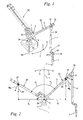
- Fig. 1 shows in a perspective view a manually guided articulated arm 30 embodied in accordance with the invention.
- the articulated arm 30 comprises a stationary support 6 that is pivotable by means of a pivot joint 39 about a vertical pivot axis 40; a first arm section 3 and a second arm section 4; an articulated arm section 22; and a hand piece 1.
- the first arm section 3 is supported by means of a pivot joint 5 with a horizontal pivot axis 29 ( Fig. 2 , 3 ) on the stationary support 6.
- an additional pivot joint 19 is provided with which the second arm section 4 is pivotably supported on the first arm section 3.
- the hand piece 1 is arranged.
- the articulated arm section 22 is arranged that comprises at least two, in the illustrated embodiment three, angle pieces 23.
- the angle pieces 23 will be explained in more detail in connection with Figs. 6 and 7 .
- the articulated arm 30 is provided for manually guiding a medical treatment device.
- an optical hand piece 1 with a laser optic 2, not illustrated in detail is provided for medical treatment.
- an externally generated laser beam, illustrated by arrow 34 is guided by angled mirrors through the articulated arm 30 to the treatment location.
- other medical treatment devices for example, an ultrasound head, a dental drill or similar devices. Non-medical devices may be provided as well.
- the articulated arm referenced by reference numeral 30 and shown in solid lines, is illustrated in an angular position that is provided for operation.
- the weight force of the articulated arm 30 causes a pivot moment about the pivot joint 5 on the support 6; for compensating the weight, a spring arrangement 7 is provided which will be explained in connection with Figs. 3 to 5 in more detail.
- the articulated arm 30 can be pivoted back and forth between its operating position and a rest position in which the articulated arm is identified by reference numeral 30'. In its rest position, the articulated arm 30' rests with its hand piece 1' in the indicated support device 18.
- the articulated arm 30 can also be manually pivoted as a whole about the vertical pivot axis 40 about swivel angle ⁇ .
- the pivot axis 40 is positioned at least approximately parallel to the weight force direction so that moments caused by the weight force on the pivot joint 39 about the pivot axis 40 are of subordinate importance.
- a neutral position of the articulated arm 30 is indicated by neutral angle ⁇ 0 within which the articulated arm 30 can be moved from its illustrated operating position into the rest position indicated by 30' and placed onto the support device 18.
- the articulated arm 30 can be swivelled or deflected in the operating position about the pivot angle ⁇ in both directions.
- the correlated pivot joint 39 with vertical pivot axis 40 is provided optionally with a spring arrangement 41, not illustrated in detail and explained infra.
- the spring arrangement 41 can move the articulated arm 30 automatically from a position deflected in any direction about pivot angle ⁇ into the neutral angle position ⁇ 0 .
- a manual swivel action about the angle ⁇ is carried out against the restoring moment of the spring arrangement 41.
- the automatic restoring action into the neutral angle ⁇ 0 enables a simplified transition into the rest position 30'.
- Fig. 2 shows the arrangement according to Fig. 1 in a side view.
- a vertical direction 17 has been selected that extends through a pivot axis 29 of the pivot joint 5 positioned between the first arm section 3 and the stationary support 6.
- the pivot axis 29 is horizontal and thus at a right angle to the vertical direction 17 or to the weight force direction.
- a positive pivot angle range + ⁇ of the arm section 3 is provided relative to the vertical direction 17.
- the articulated arm 30 is shown within the positive pivot angle range + ⁇ at a balance angle ⁇ 1 to be described infra in connection with Fig. 4 .
- the second arm section 4 is pivotable relative to the first arm section 3 at the pivot joint 19 about the angle ⁇ .
- the pivot axis of the pivot joint 19 is also horizontal and parallel to the pivot axis 29.
- the hand piece 1 has been released by the operator so that the arm section 4 with the hand piece 1 is freely suspended under the action of the weight force. Based on this position, by manually guiding the hand piece 1 the pivot angle ⁇ can be enlarged or decreased. Moreover, a greater or smaller pivot angle ⁇ relative to the balance angle ⁇ 1 can be adjusted.
- the movable part of the articulated arm 30 has a center of gravity 27 in which a weight force 28 acts parallel to the vertical direction 17.
- the weight force 28 relative to the pivot axis 29 of the pivot joint 5 has a distance vector from the pivot axis 29 to the center of gravity 27, the horizontal projection of the distance vector defining a lever arm R 1 .
- the cross product of weight force 28 and lever arm R 1 results in a weight force moment Mg 1 , its vector being disposed parallel to the pivot axis 29.
- the weight force moment Mg 1 acts in the clockwise direction on the first arm section 30, and tends to increase the absolute value of the pivot angle ⁇ .
- the course of the weight force moment Mg 1 as a function of the pivot angle ⁇ is essentially sinus-shaped.
- the movable part of the articulated arm 30 can be pivoted through the vertical direction 17 into a negative angle range - ⁇ .
- a resting angle ⁇ 2 is provided in which the articulated arm 30' rests in the support device 18 ( Fig. 1 ).
- a weight force 28' acts with a lever arm R 2 about the pivot axis 29 of the pivot joint 5. This leads to a weight force moment Mg 2 acting counterclockwise in the direction of the resting angle ⁇ 2 , analog to the weight force moment Mg 1 at a positive pivot angle ⁇ .
- the spring arrangement 7 is provided that is schematically indicated in Fig. 1 and illustrated in detail in the perspective view of Fig. 3 .
- the spring arrangement 7 has a cam disk 8 and a pressure member 9 that rests against the circumferential contour of the cam disk 8 under spring pretension and is guided along the contour of the cam disk 8 as a function of the pivot angle ⁇ of the arm section 3 ( Fig. 2 ).
- the cam disk 8 is connected to the pivotable arm section 3 so as to be entrained by it.
- the pressure member 9 is secured by means of a linear guide 11 on the stationary support 6.
- the pressure member 9 can be a glide shoe or a similar device and is configured in the illustrated embodiment as a ball bearing-supported roller 10 that rolls on the circumferential contour of the cam disk 8.
- a pair of coil pressure springs 15 is part of the spring arrangement 7; the springs 15 force with elastic pretension the pressure member 9 against the circumferential contour of the cam disk 8.
- the coil pressure springs 15 it is also possible to employ a leg spring or the like that forces the pressure member 9 by means of a pivot arm against the cam disk 8.
- the coil pressure springs 15 act on the linear guide 11 by means of which the pressure member 9 is forced by a straight, linear movement against the cam disk 8.
- the linear guide 11 comprises two parallel guide rods 12 on which a guide member 13 supporting the pressure member 9 is guided with two linear slide bearings 14.
- the longitudinal axes of the guide rods 12 are positioned approximately radially to the pivot axis 29 of the pivot joint 5 so that the guide member 13 together with the pressure member 9 is forced radially inwardly toward the pivot axis 29 against the outer circumferential contour of the cam disk 8 from the exterior.
- a reverse configuration can be expedient in which the cam disk 8 has an opening with an inner curved contour wherein the pressure member 9 is forced radially from the interior outwardly against this inner contour in the radial direction.
- a further part of the spring arrangement 7 is comprised of a manually operated device 16 that requires no tools for actuation and enables adjustment of the spring pretension.
- a manually operated device 16 that requires no tools for actuation and enables adjustment of the spring pretension.
- two parallel guides 33 are provided that pass through the two coil pressure springs 15; a pressure plate 31 is axially movably guided on the guides 33.
- the manually actuatable knurled screw 32 is provided for axial movement of the pressure plate 31 relative to the support 6 so that the spring pretension of the coil pressure springs 15 arranged therebetween can be adjusted or matched.
- the longitudinal axes of the coil pressure springs 15 and of the guides 33 are positioned axis-parallel to the two guide rods 12.
- Fig. 4 shows a side view of the arrangement according to Fig. 3 with the arm section 3 at the balance angle ⁇ 1 .
- Fig. 2 By looking also at Fig. 2 , wherein the same features are identified with same reference numerals, it is apparent that at the resting angle ⁇ 1 the weight force moment Mg 1 is acting in the direction of the positive pivot angle range + ⁇ .
- the circumferential contour of the cam disk 8 and the spring pretension of the pressure member 9 adjusted in accordance with Fig. 3 are matched to one another in such a way that the pressure member 9 with its force F 1 acts with a lever arm r 1 relative to the pivot axis 29 on the circumferential contour of the cam disk 8.
- the lever arm r 1 is the projection of the distance vector between the pivot axis 29 and the contact point of the pressure member 9 and the cam disk 8 onto a plane that is perpendicular to the force F 1 and includes the pivot axis 29.
- the force F 1 and the lever arm r 1 generate a restoring moment Mr 1 , whose vector being disposed parallel to the pivot axis 29.
- the restoring moment Mr 1 counteracts the weight force moment Mg 1 and acts on the first arm section 30 toward the vertical direction 17.
- the absolute value of both moments is identical but oppositely oriented. They are in balance so that a resulting moment M 1 acting about pivot axis 29 is generated that has the absolute value zero.
- the balance between the weight force moment Mg 1 and the restoring moment Mr 1 is a stable balance so that the articulated arm 30 at the balance angle ⁇ 1 according to Fig. 2 maintains its position automatically even when the hand piece 1 ( Fig. 2 ) is let go of.
- Fig. 5 shows the arrangement according to Fig. 4 with the first arm section 3' at the rest angle ⁇ 2 wherein the weight force moment Mg 2 according to Fig. 2 acts clockwise in the direction of the negative pivot angle range - ⁇ , i.e., has the tendency to enlarge the absolute value of the resting angle ⁇ 2 .
- the contour of the cam disk 8 and the spring pretension of the pressure member 9 are adjusted relative to one another such that at the resting angle ⁇ 2 the pressure member 9 acts with pressure force F 2 against the circumferential contour of the cam disk 8; the pressure force F 2 has a lever arm r 2 relative to the pivot axis 29.
- Pressure force F 2 , lever arm r 2 and a resulting restoring moment Mr 2 are defined analog to pressure force F 1 , lever arm r 1 and restoring moment Mr 1 .
- the pressure force F 2 generates together with the corresponding lever arm r 2 a counterclockwise acting restoring moment Mr 2 in the direction toward the positive pivot angle range + ⁇ and thus opposite to the weight force moment Mg 2 .
- the restoring moment Mr 2 has a smaller absolute value in comparison to the weight force moment Mg 2 so that the resulting total moment M 2 acting on the arm section 3' acts in the clockwise direction, i.e., has the tendency to enlarge the resting angle ⁇ 2 of the arm section 3'. In this way, the arm section 3' or the entire movable part of the articulated arm 30' is forced into the support device 18 ( Fig. 1 ).
- the restoring moment Mr 2 acts however as a relief so that only minimal forces or moments must be applied by hand in order to lift the articulated arm 30' from the position defined by resting angle ⁇ 2 and to move it into the operating position 30 according to Fig. 4 .
- the weight force moment Mg is approximately zero when the articulated arm 30 is positioned perpendicularly to the vertical direction 17.
- the contour of the cam disk 8 and the pressure force of the pressure member 9 are adjusted relative to one another such that in this position a restoring moment Mr corresponding to the restoring moment Mr 1 according to Fig. 4 results.
- a small resulting moment M is generated in accordance with the resulting moment M 2 according to Fig. 5 .
- the adjustment of the spring arrangement 7 ( Fig. 3 ) is selected such that the total moment M 2 within the entire negative pivot angle range - ⁇ , including the vertical direction 17, is oriented in the direction toward the support device 18 ( Fig. 1 ).
- the total moment M 2 in accordance with illustration of Fig. 5 is of a small, approximately constant absolute value.
- the spring arrangement 41 acting about the vertical pivot axis 40 of the pivot joint 39 and illustrated in Fig. 1 is configured according to the same principle as the spring arrangement 7 according to Figs. 1 and 3 to 5 .
- the contour of a corresponding cam disk 8 and the spring pretension of a corresponding pressure member 9 are adjusted relative to one another such that the return of the articulated arm 30 into the neutral angle ⁇ 0 is initiated as described in connection with Fig. 1 .
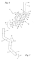
- Fig. 6 shows an enlarged side view of the articulated arm 30 in the area of its articulated arm section 22 arranged between the second arm section 4 and the hand piece 1.
- Three angle pieces 23 are provided that each have two arm segments 24, 25 positioned at a fixed angle ⁇ relative to one another.
- the three angle pieces 23 are configured to be identical wherein a long arm segment 24 of a first angle piece 23 adjoins a short arm segment 25 of the neighboring angle piece 23.
- the free end 21 of the second arm section 4 adjoins a short arm segment 25 of the neighboring angle piece 23 while the hand piece 1 adjoins a long arm segment 24 of the neighboring angle piece 23.
- Segment axes 35, 36 of the arm segments 24, 25 are positioned at a fixed unchangeable angle ⁇ relative to one another; the angle ⁇ differs from 90° and is preferably greater than 100°; in particular, it is approximately 105° in the illustrated embodiment.
- each angle piece 23 In the corner areas of each angle piece 23 a mirror 38 is provided that is positioned perpendicularly to the bisecting line of the angle ⁇ . In this way, the laser beam that is introduced parallel to the longitudinal axis of the second arm section 4 in accordance with arrow 34 is guided through the angle pieces 23 parallel to the segment axes 35, 36 and parallel to the longitudinal axis of the hand piece 1.
- a torsion joint 26 of the articulated arm 30 is provided and forms a joint plane 37, respectively.
- the hand piece 1, the second arm section 4, and all three angle pieces 23 are rotatable relative to one another in the joint planes 37 about their respective longitudinal axes or segment axes 35, 36 in a torsion movement.
- torsion moments result in the individual joint planes 37, the torsion vectors being parallel to the segment axes 35, 36, and causing an articulated movement about the respective segment axes 35, 36.
- a free movement of the hand piece 1 is limited.
- a swivelling movement of the end piece 1 whithin this plane as indicated by arrow 42 is impossible.
- a displacement of the angle pieces 23 slightly out of the common plane is necessary.
- at least a minimal out-of-plane displacement is essentially present all the time, as depicted in Fig. 7 .
- the out-of-plane displacement of individual angle pieces 23 is increased or decreased, as indicated for example by an arrow 43 for the middle angle piece 23.
Landscapes
- Health & Medical Sciences (AREA)
- Engineering & Computer Science (AREA)
- Public Health (AREA)
- Life Sciences & Earth Sciences (AREA)
- General Engineering & Computer Science (AREA)
- Mechanical Engineering (AREA)
- Oral & Maxillofacial Surgery (AREA)
- Dentistry (AREA)
- Epidemiology (AREA)
- Veterinary Medicine (AREA)
- Animal Behavior & Ethology (AREA)
- General Health & Medical Sciences (AREA)
- Robotics (AREA)
- Physics & Mathematics (AREA)
- Optics & Photonics (AREA)
- Manipulator (AREA)
- Physical Vapour Deposition (AREA)
Priority Applications (2)
| Application Number | Priority Date | Filing Date | Title |
|---|---|---|---|
| EP06025760A EP1932631B1 (fr) | 2006-12-13 | 2006-12-13 | Bras articulé commandé manuellement |
| AT06025760T ATE544419T1 (de) | 2006-12-13 | 2006-12-13 | Manuell geführter gelenkarm |
Applications Claiming Priority (1)
| Application Number | Priority Date | Filing Date | Title |
|---|---|---|---|
| EP06025760A EP1932631B1 (fr) | 2006-12-13 | 2006-12-13 | Bras articulé commandé manuellement |
Publications (2)
| Publication Number | Publication Date |
|---|---|
| EP1932631A1 true EP1932631A1 (fr) | 2008-06-18 |
| EP1932631B1 EP1932631B1 (fr) | 2012-02-08 |
Family
ID=38015279
Family Applications (1)
| Application Number | Title | Priority Date | Filing Date |
|---|---|---|---|
| EP06025760A Active EP1932631B1 (fr) | 2006-12-13 | 2006-12-13 | Bras articulé commandé manuellement |
Country Status (2)
| Country | Link |
|---|---|
| EP (1) | EP1932631B1 (fr) |
| AT (1) | ATE544419T1 (fr) |
Cited By (4)
| Publication number | Priority date | Publication date | Assignee | Title |
|---|---|---|---|---|
| DE102014104175B4 (de) * | 2013-03-29 | 2015-07-30 | Fanuc Corporation | Mehrgelenkrobotor mit Gasverfahren und Schätzverfahren für den Gasfederinnendruck |
| JP2017030099A (ja) * | 2015-08-03 | 2017-02-09 | パスカルエンジニアリング株式会社 | ロボット用バランサ装置 |
| CN114162358A (zh) * | 2022-02-11 | 2022-03-11 | 清华大学 | 一种体感微低重力模拟装置 |
| CN114179129A (zh) * | 2021-12-30 | 2022-03-15 | 伯朗特机器人股份有限公司 | 一种机器人辅助支撑装置的设置方法 |
Families Citing this family (1)
| Publication number | Priority date | Publication date | Assignee | Title |
|---|---|---|---|---|
| CN104608142B (zh) * | 2015-01-09 | 2016-06-08 | 河北工业大学 | 一种旋转型变刚度柔性关节 |
Citations (6)
| Publication number | Priority date | Publication date | Assignee | Title |
|---|---|---|---|---|
| DD154282A1 (de) * | 1980-11-13 | 1982-03-10 | Roland Baudich | Einrichtung fuer den gewichtsausgleich bei handhabungsmitteln mit drehgelenken |
| US6253458B1 (en) * | 1998-12-08 | 2001-07-03 | Faro Technologies, Inc. | Adjustable counterbalance mechanism for a coordinate measurement machine |
| WO2003100313A1 (fr) * | 2002-05-23 | 2003-12-04 | Coral S.P.A. | Dispositif d'equilibrage d'un bras tournant autour d'un axe de rotation, par exemple, d'un bras supportant une station de travail universelle a conduit de fumee ou de gaz d'echappement |
| US20040245419A1 (en) * | 2003-01-17 | 2004-12-09 | Sweere Harry C. | Support arm |
| EP1632320A1 (fr) * | 2004-09-06 | 2006-03-08 | Dürr Systems GmbH | Poignet de robot avec entraînemet de tuyau pour la rotation d'un tuyau d'alimentation, et procédé associé |
| WO2007054327A1 (fr) * | 2005-11-10 | 2007-05-18 | Carl Zeiss Surgical Gmbh | Dispositif de support a equilibrage de poids |
-
2006
- 2006-12-13 AT AT06025760T patent/ATE544419T1/de active
- 2006-12-13 EP EP06025760A patent/EP1932631B1/fr active Active
Patent Citations (6)
| Publication number | Priority date | Publication date | Assignee | Title |
|---|---|---|---|---|
| DD154282A1 (de) * | 1980-11-13 | 1982-03-10 | Roland Baudich | Einrichtung fuer den gewichtsausgleich bei handhabungsmitteln mit drehgelenken |
| US6253458B1 (en) * | 1998-12-08 | 2001-07-03 | Faro Technologies, Inc. | Adjustable counterbalance mechanism for a coordinate measurement machine |
| WO2003100313A1 (fr) * | 2002-05-23 | 2003-12-04 | Coral S.P.A. | Dispositif d'equilibrage d'un bras tournant autour d'un axe de rotation, par exemple, d'un bras supportant une station de travail universelle a conduit de fumee ou de gaz d'echappement |
| US20040245419A1 (en) * | 2003-01-17 | 2004-12-09 | Sweere Harry C. | Support arm |
| EP1632320A1 (fr) * | 2004-09-06 | 2006-03-08 | Dürr Systems GmbH | Poignet de robot avec entraînemet de tuyau pour la rotation d'un tuyau d'alimentation, et procédé associé |
| WO2007054327A1 (fr) * | 2005-11-10 | 2007-05-18 | Carl Zeiss Surgical Gmbh | Dispositif de support a equilibrage de poids |
Cited By (6)
| Publication number | Priority date | Publication date | Assignee | Title |
|---|---|---|---|---|
| DE102014104175B4 (de) * | 2013-03-29 | 2015-07-30 | Fanuc Corporation | Mehrgelenkrobotor mit Gasverfahren und Schätzverfahren für den Gasfederinnendruck |
| JP2017030099A (ja) * | 2015-08-03 | 2017-02-09 | パスカルエンジニアリング株式会社 | ロボット用バランサ装置 |
| CN114179129A (zh) * | 2021-12-30 | 2022-03-15 | 伯朗特机器人股份有限公司 | 一种机器人辅助支撑装置的设置方法 |
| CN114179129B (zh) * | 2021-12-30 | 2024-03-22 | 伯朗特机器人股份有限公司 | 一种机器人辅助支撑装置的设置方法 |
| CN114162358A (zh) * | 2022-02-11 | 2022-03-11 | 清华大学 | 一种体感微低重力模拟装置 |
| CN114162358B (zh) * | 2022-02-11 | 2022-05-17 | 清华大学 | 一种体感微低重力模拟装置 |
Also Published As
| Publication number | Publication date |
|---|---|
| ATE544419T1 (de) | 2012-02-15 |
| EP1932631B1 (fr) | 2012-02-08 |
Similar Documents
| Publication | Publication Date | Title |
|---|---|---|
| US9186222B2 (en) | Manually guided articulated arm | |
| US11166569B2 (en) | Chair | |
| EP2119411B1 (fr) | Appareil de support pour instrument médical | |
| US20080018211A1 (en) | Task oriented workstation with adjustable supports and variable assist pulley | |
| EP2886015B1 (fr) | Chaise avec dossier ajustable | |
| JP4212678B2 (ja) | スタンド | |
| JP5706477B2 (ja) | 重量補償式の保持装置 | |
| JPS6146275B2 (fr) | ||
| JP2010529874A (ja) | 前腕回転機構および該機構を含む矯正器 | |
| CN208478212U (zh) | 扭簧件、摇杆机构和遥控器 | |
| EP1932631B1 (fr) | Bras articulé commandé manuellement | |
| NL1018687C2 (nl) | Scharnierconstructie en scharnieractuator, in het bijzonder voor een buitenspiegel van een motorvoertuig. | |
| JP2003301879A (ja) | バネ装置 | |
| KR102284387B1 (ko) | 수술 시스템 | |
| CA2801188A1 (fr) | Equipement de robotique collaborative | |
| EP0404845A1 (fr) | Appareil d'amenee de faisceau | |
| US20050224670A1 (en) | Stand, in particular for surgical microscopes, having an energy storage element | |
| CA2682418C (fr) | Appareil dentaire a bras articule reglable | |
| JPH11153293A (ja) | 重量つり合いのためのエネルギー蓄積部を有するスタンド | |
| KR20200145398A (ko) | 수술용 마스터 장치 및 이를 포함하는 수술 시스템 | |
| AU2003227038B2 (en) | Tripod head, in particular camera tripod head | |
| WO2018015994A1 (fr) | Appareil de support de dispositif médical | |
| KR102846545B1 (ko) | 분리형 밸런싱 유닛 | |
| US20250266671A1 (en) | Supporting Device and Robot Arm | |
| JP7665549B2 (ja) | アーム型助力装置 |
Legal Events
| Date | Code | Title | Description |
|---|---|---|---|
| PUAI | Public reference made under article 153(3) epc to a published international application that has entered the european phase |
Free format text: ORIGINAL CODE: 0009012 |
|
| AK | Designated contracting states |
Kind code of ref document: A1 Designated state(s): AT BE BG CH CY CZ DE DK EE ES FI FR GB GR HU IE IS IT LI LT LU LV MC NL PL PT RO SE SI SK TR |
|
| AX | Request for extension of the european patent |
Extension state: AL BA HR MK RS |
|
| 17P | Request for examination filed |
Effective date: 20080715 |
|
| 17Q | First examination report despatched |
Effective date: 20080814 |
|
| AKX | Designation fees paid |
Designated state(s): AT BE BG CH CY CZ DE DK EE ES FI FR GB GR HU IE IS IT LI LT LU LV MC NL PL PT RO SE SI SK TR |
|
| REG | Reference to a national code |
Ref country code: DE Ref legal event code: R079 Ref document number: 602006027510 Country of ref document: DE Free format text: PREVIOUS MAIN CLASS: B25J0019000000 Ipc: A61C0019000000 |
|
| GRAP | Despatch of communication of intention to grant a patent |
Free format text: ORIGINAL CODE: EPIDOSNIGR1 |
|
| RIC1 | Information provided on ipc code assigned before grant |
Ipc: A61C 19/00 20060101AFI20110822BHEP Ipc: B25J 19/00 20060101ALI20110822BHEP Ipc: F16M 11/04 20060101ALI20110822BHEP Ipc: A61C 1/00 20060101ALI20110822BHEP |
|
| GRAS | Grant fee paid |
Free format text: ORIGINAL CODE: EPIDOSNIGR3 |
|
| GRAA | (expected) grant |
Free format text: ORIGINAL CODE: 0009210 |
|
| AK | Designated contracting states |
Kind code of ref document: B1 Designated state(s): AT BE BG CH CY CZ DE DK EE ES FI FR GB GR HU IE IS IT LI LT LU LV MC NL PL PT RO SE SI SK TR |
|
| REG | Reference to a national code |
Ref country code: GB Ref legal event code: FG4D |
|
| REG | Reference to a national code |
Ref country code: CH Ref legal event code: EP Ref country code: AT Ref legal event code: REF Ref document number: 544419 Country of ref document: AT Kind code of ref document: T Effective date: 20120215 |
|
| REG | Reference to a national code |
Ref country code: DE Ref legal event code: R096 Ref document number: 602006027510 Country of ref document: DE Effective date: 20120412 |
|
| REG | Reference to a national code |
Ref country code: NL Ref legal event code: VDEP Effective date: 20120208 |
|
| LTIE | Lt: invalidation of european patent or patent extension |
Effective date: 20120208 |
|
| PG25 | Lapsed in a contracting state [announced via postgrant information from national office to epo] |
Ref country code: NL Free format text: LAPSE BECAUSE OF FAILURE TO SUBMIT A TRANSLATION OF THE DESCRIPTION OR TO PAY THE FEE WITHIN THE PRESCRIBED TIME-LIMIT Effective date: 20120208 Ref country code: IS Free format text: LAPSE BECAUSE OF FAILURE TO SUBMIT A TRANSLATION OF THE DESCRIPTION OR TO PAY THE FEE WITHIN THE PRESCRIBED TIME-LIMIT Effective date: 20120608 Ref country code: LT Free format text: LAPSE BECAUSE OF FAILURE TO SUBMIT A TRANSLATION OF THE DESCRIPTION OR TO PAY THE FEE WITHIN THE PRESCRIBED TIME-LIMIT Effective date: 20120208 |
|
| PG25 | Lapsed in a contracting state [announced via postgrant information from national office to epo] |
Ref country code: FI Free format text: LAPSE BECAUSE OF FAILURE TO SUBMIT A TRANSLATION OF THE DESCRIPTION OR TO PAY THE FEE WITHIN THE PRESCRIBED TIME-LIMIT Effective date: 20120208 Ref country code: BE Free format text: LAPSE BECAUSE OF FAILURE TO SUBMIT A TRANSLATION OF THE DESCRIPTION OR TO PAY THE FEE WITHIN THE PRESCRIBED TIME-LIMIT Effective date: 20120208 Ref country code: PT Free format text: LAPSE BECAUSE OF FAILURE TO SUBMIT A TRANSLATION OF THE DESCRIPTION OR TO PAY THE FEE WITHIN THE PRESCRIBED TIME-LIMIT Effective date: 20120608 Ref country code: LV Free format text: LAPSE BECAUSE OF FAILURE TO SUBMIT A TRANSLATION OF THE DESCRIPTION OR TO PAY THE FEE WITHIN THE PRESCRIBED TIME-LIMIT Effective date: 20120208 Ref country code: PL Free format text: LAPSE BECAUSE OF FAILURE TO SUBMIT A TRANSLATION OF THE DESCRIPTION OR TO PAY THE FEE WITHIN THE PRESCRIBED TIME-LIMIT Effective date: 20120208 Ref country code: GR Free format text: LAPSE BECAUSE OF FAILURE TO SUBMIT A TRANSLATION OF THE DESCRIPTION OR TO PAY THE FEE WITHIN THE PRESCRIBED TIME-LIMIT Effective date: 20120509 |
|
| REG | Reference to a national code |
Ref country code: AT Ref legal event code: MK05 Ref document number: 544419 Country of ref document: AT Kind code of ref document: T Effective date: 20120208 |
|
| PG25 | Lapsed in a contracting state [announced via postgrant information from national office to epo] |
Ref country code: CY Free format text: LAPSE BECAUSE OF FAILURE TO SUBMIT A TRANSLATION OF THE DESCRIPTION OR TO PAY THE FEE WITHIN THE PRESCRIBED TIME-LIMIT Effective date: 20120208 |
|
| PG25 | Lapsed in a contracting state [announced via postgrant information from national office to epo] |
Ref country code: SE Free format text: LAPSE BECAUSE OF FAILURE TO SUBMIT A TRANSLATION OF THE DESCRIPTION OR TO PAY THE FEE WITHIN THE PRESCRIBED TIME-LIMIT Effective date: 20120208 Ref country code: SI Free format text: LAPSE BECAUSE OF FAILURE TO SUBMIT A TRANSLATION OF THE DESCRIPTION OR TO PAY THE FEE WITHIN THE PRESCRIBED TIME-LIMIT Effective date: 20120208 Ref country code: EE Free format text: LAPSE BECAUSE OF FAILURE TO SUBMIT A TRANSLATION OF THE DESCRIPTION OR TO PAY THE FEE WITHIN THE PRESCRIBED TIME-LIMIT Effective date: 20120208 Ref country code: CZ Free format text: LAPSE BECAUSE OF FAILURE TO SUBMIT A TRANSLATION OF THE DESCRIPTION OR TO PAY THE FEE WITHIN THE PRESCRIBED TIME-LIMIT Effective date: 20120208 Ref country code: RO Free format text: LAPSE BECAUSE OF FAILURE TO SUBMIT A TRANSLATION OF THE DESCRIPTION OR TO PAY THE FEE WITHIN THE PRESCRIBED TIME-LIMIT Effective date: 20120208 Ref country code: DK Free format text: LAPSE BECAUSE OF FAILURE TO SUBMIT A TRANSLATION OF THE DESCRIPTION OR TO PAY THE FEE WITHIN THE PRESCRIBED TIME-LIMIT Effective date: 20120208 |
|
| PG25 | Lapsed in a contracting state [announced via postgrant information from national office to epo] |
Ref country code: SK Free format text: LAPSE BECAUSE OF FAILURE TO SUBMIT A TRANSLATION OF THE DESCRIPTION OR TO PAY THE FEE WITHIN THE PRESCRIBED TIME-LIMIT Effective date: 20120208 |
|
| PLBE | No opposition filed within time limit |
Free format text: ORIGINAL CODE: 0009261 |
|
| STAA | Information on the status of an ep patent application or granted ep patent |
Free format text: STATUS: NO OPPOSITION FILED WITHIN TIME LIMIT |
|
| 26N | No opposition filed |
Effective date: 20121109 |
|
| PG25 | Lapsed in a contracting state [announced via postgrant information from national office to epo] |
Ref country code: AT Free format text: LAPSE BECAUSE OF FAILURE TO SUBMIT A TRANSLATION OF THE DESCRIPTION OR TO PAY THE FEE WITHIN THE PRESCRIBED TIME-LIMIT Effective date: 20120208 |
|
| REG | Reference to a national code |
Ref country code: DE Ref legal event code: R097 Ref document number: 602006027510 Country of ref document: DE Effective date: 20121109 |
|
| PG25 | Lapsed in a contracting state [announced via postgrant information from national office to epo] |
Ref country code: ES Free format text: LAPSE BECAUSE OF FAILURE TO SUBMIT A TRANSLATION OF THE DESCRIPTION OR TO PAY THE FEE WITHIN THE PRESCRIBED TIME-LIMIT Effective date: 20120519 |
|
| PG25 | Lapsed in a contracting state [announced via postgrant information from national office to epo] |
Ref country code: BG Free format text: LAPSE BECAUSE OF FAILURE TO SUBMIT A TRANSLATION OF THE DESCRIPTION OR TO PAY THE FEE WITHIN THE PRESCRIBED TIME-LIMIT Effective date: 20120508 Ref country code: MC Free format text: LAPSE BECAUSE OF NON-PAYMENT OF DUE FEES Effective date: 20121231 |
|
| REG | Reference to a national code |
Ref country code: CH Ref legal event code: PL |
|
| REG | Reference to a national code |
Ref country code: IE Ref legal event code: MM4A |
|
| REG | Reference to a national code |
Ref country code: FR Ref legal event code: ST Effective date: 20130830 |
|
| PG25 | Lapsed in a contracting state [announced via postgrant information from national office to epo] |
Ref country code: IE Free format text: LAPSE BECAUSE OF NON-PAYMENT OF DUE FEES Effective date: 20121213 Ref country code: CH Free format text: LAPSE BECAUSE OF NON-PAYMENT OF DUE FEES Effective date: 20121231 Ref country code: LI Free format text: LAPSE BECAUSE OF NON-PAYMENT OF DUE FEES Effective date: 20121231 |
|
| PG25 | Lapsed in a contracting state [announced via postgrant information from national office to epo] |
Ref country code: FR Free format text: LAPSE BECAUSE OF NON-PAYMENT OF DUE FEES Effective date: 20130102 |
|
| PG25 | Lapsed in a contracting state [announced via postgrant information from national office to epo] |
Ref country code: TR Free format text: LAPSE BECAUSE OF FAILURE TO SUBMIT A TRANSLATION OF THE DESCRIPTION OR TO PAY THE FEE WITHIN THE PRESCRIBED TIME-LIMIT Effective date: 20120208 |
|
| PG25 | Lapsed in a contracting state [announced via postgrant information from national office to epo] |
Ref country code: LU Free format text: LAPSE BECAUSE OF NON-PAYMENT OF DUE FEES Effective date: 20121213 |
|
| PG25 | Lapsed in a contracting state [announced via postgrant information from national office to epo] |
Ref country code: HU Free format text: LAPSE BECAUSE OF FAILURE TO SUBMIT A TRANSLATION OF THE DESCRIPTION OR TO PAY THE FEE WITHIN THE PRESCRIBED TIME-LIMIT Effective date: 20061213 |
|
| PGFP | Annual fee paid to national office [announced via postgrant information from national office to epo] |
Ref country code: DE Payment date: 20251211 Year of fee payment: 20 |
|
| PGFP | Annual fee paid to national office [announced via postgrant information from national office to epo] |
Ref country code: GB Payment date: 20251219 Year of fee payment: 20 |
|
| PGFP | Annual fee paid to national office [announced via postgrant information from national office to epo] |
Ref country code: IT Payment date: 20251223 Year of fee payment: 20 |