EP1932743B1 - Fixation axiale pour transpalette - Google Patents
Fixation axiale pour transpalette Download PDFInfo
- Publication number
- EP1932743B1 EP1932743B1 EP07079512.5A EP07079512A EP1932743B1 EP 1932743 B1 EP1932743 B1 EP 1932743B1 EP 07079512 A EP07079512 A EP 07079512A EP 1932743 B1 EP1932743 B1 EP 1932743B1
- Authority
- EP
- European Patent Office
- Prior art keywords
- pallet
- pallet truck
- truck
- roller
- elongate member
- Prior art date
- Legal status (The legal status is an assumption and is not a legal conclusion. Google has not performed a legal analysis and makes no representation as to the accuracy of the status listed.)
- Not-in-force
Links
Images


Classifications
-
- B—PERFORMING OPERATIONS; TRANSPORTING
- B62—LAND VEHICLES FOR TRAVELLING OTHERWISE THAN ON RAILS
- B62B—HAND-PROPELLED VEHICLES, e.g. HAND CARTS OR PERAMBULATORS; SLEDGES
- B62B3/00—Hand carts having more than one axis carrying transport wheels; Steering devices therefor; Equipment therefor
- B62B3/04—Hand carts having more than one axis carrying transport wheels; Steering devices therefor; Equipment therefor involving means for grappling or securing in place objects to be carried; Loading or unloading equipment
- B62B3/06—Hand carts having more than one axis carrying transport wheels; Steering devices therefor; Equipment therefor involving means for grappling or securing in place objects to be carried; Loading or unloading equipment for simply clearing the load from the ground
-
- B—PERFORMING OPERATIONS; TRANSPORTING
- B60—VEHICLES IN GENERAL
- B60B—VEHICLE WHEELS; CASTORS; AXLES FOR WHEELS OR CASTORS; INCREASING WHEEL ADHESION
- B60B35/00—Axle units; Parts thereof ; Arrangements for lubrication of axles
- B60B35/02—Dead axles, i.e. not transmitting torque
- B60B35/04—Dead axles, i.e. not transmitting torque straight
-
- B—PERFORMING OPERATIONS; TRANSPORTING
- B62—LAND VEHICLES FOR TRAVELLING OTHERWISE THAN ON RAILS
- B62B—HAND-PROPELLED VEHICLES, e.g. HAND CARTS OR PERAMBULATORS; SLEDGES
- B62B2301/00—Wheel arrangements; Steering; Stability; Wheel suspension
- B62B2301/08—Wheel arrangements; Steering; Stability; Wheel suspension comprising additional wheels to increase stability
Definitions
- the present invention relates to an axle bar for a pallet truck.
- a pallet truck is a known device which is utilised to enable laden pallets to be moved over smooth surfaces, for example in a warehouse.
- a truck typically comprises a wheeled "U" shaped frame, similar in shape to that of the fork of a fork-lift truck upon which are provided a pair of pallet fingers capable of being elevated.
- the frame is provided with wheels and rollers spaced in a tricycle arrangement.
- the tricycle arrangement comprises a roller provided on the underside of each fork, and a third set of wheels or rollers provided at the root of the fork on a member extending therebetween.
- the third set of wheels are typically pivotable in the manner of a castor so as to enable the truck to be moved over a surface in any given direction.
- a hydraulic ram Disposed between the frame and the pallet fingers is a hydraulic ram which may be extended so as to elevate the pallet fingers.
- the hydraulic ram of such a pallet truck enables the pallet fingers to be raised and lowered within a range of around 120 mm.
- the frame and pallet fingers are positioned under a load and the ram extended so that the load is lifted by the fingers.
- An operator can subsequently manoeuvre the pallet truck by a handle thereof so as to move the load to a desired location.
- High lift pallet trucks having an elevation range greater than 120 mm are also available. Such high lift trucks are commonly referred to as stacking trucks.
- the tricycle arrangement of the wheels of the pallet truck can lead to stability problems, especially in instances where the truck is used to lift rolling or unstable items.
- the pallet fingers of the pallet truck may be provided with a low friction surface, such as a roller bed, to assist in the loading and unloading of items.
- the presence of a low friction surface increases the possibility of a load shifting relative to the pallet fingers when the truck is moved and hence destabilising the truck as a whole.
- the third set of wheels or rollers may be repositioned outwardly from the front to rear centreline of the truck such that a wheel or roller is provided outboard of the frame on either side thereof. While the repositioning of the third set of wheels or rollers increases the stability of the truck it will be appreciated that the track width of the third set of wheels or rollers is greater than the track width of the fork rollers.
- US 2006/0231312 is directed to a weight distribution assembly for a materials handling vehicle according to the features of the preamble of claim 1.
- the assembly includes first and second castors which are located on opposing sides of a drive wheel of the vehicle.
- a pallet truck axle bar comprising an elongate member having at opposed ends thereof a wheel assembly, the elongate member being provided between the wheel assemblies with mounting points to enable the bar to be connected to the frame of a pallet truck characterised in that the mounting points are in use connectable to the fork roller brackets of a pallet truck, and the length of the elongate member is greater than the width of the pallet fingers of a pallet truck, such that, in use, the wheel assemblies are provided on either side of the pallet of a pallet truck so as to increase the truck width of the pallet fork truck across the pallet fingers.
- the axle bar of the present invention provides a simple and easily installed way of increasing the track width of a pallet truck across the pallet fingers thereof in order to enhance the stability of the pallet truck and to lower rolling resistance.
- the axle bar may be provided with a stabiliser.
- the stabiliser may take the form of a roller which is mounted to the elongate member intermediate the wheel assemblies.
- the stabiliser roller comprises a lead in roller assembly removed from the underside of a pallet fork of a pallet truck.
- the axle bar may be provided with a plurality of such stabilisers.
- Each mounting point preferably includes a member having a bore extending therethrough.
- the member has a width which is substantially equal to that of a fork roller such that the member is receivable in the fork roller mounting.
- the fork roller is mounted to a forked bracket.
- the mounting point member may thus be received by the forked bracket and an axle member, such as a pin, inserted through the bore and the bracket to retain the axle bar.
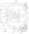
- the bar 10 includes a transverse member 12 which extends between opposed wheel assemblies 14.
- Each wheel assembly 14 comprises a back plate 16, a front plate 18, a bridging member 20 and a wheel 22.
- the plates 16,18 and bridging member 20 define a substantially "U" shaped bracket which surrounds the wheel 22.
- the wheel 22 of each assembly 14 is rotatably mounted to an axle 24 which is carried by the front and back plates 16,18.
- the axle 24 is mounted in appropriately configured bearings of the plates 16,18.
- a keeper plate 25 retained by a grub screw 27 is utilised to maintain the axle 24 in position.
- the length of the transverse member 12 is greater that the width of the frame and pallet forks of the pallet truck to which the bar 10 is intended to be fitted. As such, the wheels 22 in use are provided to either side of the frame and pallet forks.
- the transverse member 12 is substantially "L" shaped in cross-section at it's outer portions 26 and is provided with a box section portion 28 at its midway point.
- the box-section portion 28 is provided with a pair of stabilising rollers, generally designated 30, which are provided on opposing sides thereof.
- Each roller 30 comprises a roller member 32 and a bracket 34
- Each outer portion 26 of the transverse member 12 is provided with a mounting point 36 which, in use, enables the axle bar 10 to be fitted to a pallet truck.
- each mounting point 36 comprises a base 38 fixed to the transverse member 12 and a tube 40.
- the tube 40 is fixed to the base 38 and is axially aligned with the transverse member 12.
- an axle member such as a pin, can be inserted through the tube 40 and mounting feature a pallet truck frame in order to connect the axle bar 10 to the frame.
- the mounting features of the pallet truck frame to which the axle bar 10 is connectable are defined by forked brackets to which the fork rollers are usually mounted.
- the fork rollers are removed and the bar 10 mounted to fork roller brackets.
- the length of the tube 40 is substantially equal to the width of a fork roller and as such, the tube is readily receivable within a fork roller bracket
- the stabilisers 30 may comprise lead in roller assemblies which have been removed from the underside of the pallet fingers.
- the rotational axes of the wheels 22 are aligned with the longitudinal axis of the of the transverse member 12. It will be understood that the shape and size of the back plates 16 may be altered, as may the position of the transverse member 12 relative to the back plates and/or the position of each axle 24 between the plates 16,18. As such, the position of the rotational axes of the wheels 22 may be moved relative to the longitudinal axis of the transverse member 12. While two stabilising rollers 30 are shown, it will be appreciated that a greater or lesser number my be provided depending upon the intended service parameters of the pallet truck to which the bar 10 is fitted.
- each wheel 22 is greater than the diameter of the fork roller it replaces.
- the wheels 22 are of equal diameter and each may have a diameter in the range of 170 mm to 250 mm, although larger diameter wheels may be used if required.
- the front plate 18 of one of the wheel assemblies 14 is provided with a cylindrical projection generally designated 42.
- the projection 42 in use, may co-operate with a guide mechanism which is configured to guide the axle bar 10 and the pallet truck to which it is fitted along a predetermined path.
- axle bar 10 is described above as being suitable for use with a pallet truck which has had the track of its third set of wheels widened, the axle bar 10 may equally e fitted to a pallet truck having the usual narrow track arrangement for the third set of wheels.
Landscapes
- Engineering & Computer Science (AREA)
- Mechanical Engineering (AREA)
- Chemical & Material Sciences (AREA)
- Combustion & Propulsion (AREA)
- Transportation (AREA)
- Handcart (AREA)
Claims (6)
- Combinaison de transpalette et de barre d'essieu de transpalette (10), la barre d'essieu comprenant un élément allongé (12) ayant à des extrémités opposées de celle-ci un ensemble de roue (14), l'élément allongé (12) étant prévu entre les ensembles de roues (14) avec des points de montage (36) pour permettre à la barre (10) d'être connectée au châssis du transpalette, caractérisée en ce que les points de montage (36) sont en utilisation connectés aux supports de rouleaux de fourche du transpalette, et la longueur de l'élément allongé (12) est supérieure à la largeur des bras du transpalette de sorte que, en utilisation, les ensembles de roues (14) soient prévus des deux côtés des bras d'un transpalette de manière à augmenter la largeur de piste du transpalette en travers des bras.
- Combinaison selon la revendication 1, dans laquelle la barre d'essieu est dotée d'un stabilisateur (30) qui comprend un rouleau monté sur l'élément allongé (10) à une position intermédiaire entre les ensembles de roues (14).
- Combinaison selon la revendication 2, dans lequel le rouleau stabilisateur (30, 32) comprend un rouleau d'entrée de palette d'une fourche de palette d'un transpalette.
- Combinaison selon la revendication 2 ou la revendication 3, dans laquelle la barre d'essieu (10) est dotée de deux rouleaux stabilisateurs (30, 32), dont chacun est positionné sur un côté opposé de l'élément allongé (12).
- Combinaison selon l'une quelconque des revendications précédentes, dans laquelle les axes de rotation des ensembles de roues (14) sont alignés avec l'axe longitudinal de l'élément allongé (12).
- Combinaison selon l'une quelconque des revendications précédentes, dans laquelle chaque point de montage (36) inclut un élément (40) ayant un alésage s'étendant à travers celui-ci.
Applications Claiming Priority (1)
| Application Number | Priority Date | Filing Date | Title |
|---|---|---|---|
| GBGB0624686.2A GB0624686D0 (en) | 2006-12-11 | 2006-12-11 | Axle Attachment for Pallet Truck |
Publications (2)
| Publication Number | Publication Date |
|---|---|
| EP1932743A1 EP1932743A1 (fr) | 2008-06-18 |
| EP1932743B1 true EP1932743B1 (fr) | 2014-04-23 |
Family
ID=37711907
Family Applications (1)
| Application Number | Title | Priority Date | Filing Date |
|---|---|---|---|
| EP07079512.5A Not-in-force EP1932743B1 (fr) | 2006-12-11 | 2007-12-06 | Fixation axiale pour transpalette |
Country Status (3)
| Country | Link |
|---|---|
| US (1) | US20080217990A1 (fr) |
| EP (1) | EP1932743B1 (fr) |
| GB (1) | GB0624686D0 (fr) |
Family Cites Families (11)
| Publication number | Priority date | Publication date | Assignee | Title |
|---|---|---|---|---|
| GB704317A (en) * | 1952-09-23 | 1954-02-17 | Yale & Towne Mfg Co | Improvements in or relating to a motorized lift truck |
| FR2278506A1 (fr) * | 1974-04-09 | 1976-02-13 | Bouvet Lucien | Essieu universel pour diables, plateaux, porte-bouteilles et autres chariots de manutention manuelle a usage specifique ou transformable |
| NL7806778A (nl) * | 1978-06-23 | 1979-12-28 | Kooi Bv | Vorkheftruck. |
| US4392541A (en) * | 1981-05-01 | 1983-07-12 | Spyder Sales & Service, Inc. | Vehicle convertible from a tricycle two wheel drive to a four wheel four wheel drive |
| CH675868A5 (fr) * | 1988-03-16 | 1990-11-15 | Sft Ag Spontanfoerdertechnik | |
| US5253972A (en) * | 1992-01-30 | 1993-10-19 | Moore Business Forms, Inc. | Roll dolly |
| JPH0939507A (ja) * | 1995-07-31 | 1997-02-10 | Suzuki Motor Corp | 作業機の車軸装置 |
| JP3471299B2 (ja) * | 2000-07-25 | 2003-12-02 | 清三 伊藤 | 重量物運搬用車輪ユニット |
| DE50311366D1 (de) * | 2002-12-05 | 2009-05-14 | Patea Gmbh | Hülle mit Transportvorrichtung an einem faltbaren Zelt |
| DE60315001T2 (de) * | 2003-06-10 | 2008-04-17 | Merlo Project S.R.L., San Defendente Di Cervasca | Vorrichtung zum Handhaben von Paletten |
| US7770904B2 (en) | 2005-04-14 | 2010-08-10 | Nmhg Oregon, Llc | Stability system for an industrial vehicle |
-
2006
- 2006-12-11 GB GBGB0624686.2A patent/GB0624686D0/en not_active Ceased
-
2007
- 2007-12-06 EP EP07079512.5A patent/EP1932743B1/fr not_active Not-in-force
- 2007-12-11 US US12/001,233 patent/US20080217990A1/en not_active Abandoned
Also Published As
| Publication number | Publication date |
|---|---|
| GB0624686D0 (en) | 2007-01-17 |
| US20080217990A1 (en) | 2008-09-11 |
| EP1932743A1 (fr) | 2008-06-18 |
Similar Documents
| Publication | Publication Date | Title |
|---|---|---|
| EP2159185B1 (fr) | Véhicule industriel doté de deux ensembles de fourches de levage | |
| US11142232B2 (en) | Pallet jack assembly | |
| CZ20014537A3 (cs) | Vozík se zdvižnou vidlicí s omezeným poloměrem otáčení | |
| US10807849B2 (en) | Pantograph assembly for lift truck | |
| US11673781B2 (en) | Forks for industrial vehicles and method of making same | |
| EP2641862A1 (fr) | Gerbeur à conducteur à pied | |
| US6199665B1 (en) | Straddle arm for fork lift truck | |
| EP1932743B1 (fr) | Fixation axiale pour transpalette | |
| US3240372A (en) | Extensible mounting apparatus for hoists | |
| EP2014605B1 (fr) | Dispositif monte-charge et plate-forme pour dispositif monte-charge | |
| US3778080A (en) | Lift truck load wheel arrangement | |
| CN110734011B (zh) | 一种叉车的防侧翻装置 | |
| EP4296072A1 (fr) | Ensemble roue pour véhicule de manutention de matériaux | |
| EP0633176B1 (fr) | Système de transport | |
| JP5348959B2 (ja) | リフトトラック | |
| EP0341225A2 (fr) | Dispositif pour le déplacement latéral d'un véhicule | |
| NL7906341A (nl) | Laaghefwagen. | |
| JP4748961B2 (ja) | リフトトラック | |
| EP0509976A2 (fr) | Transpalette à fourche à bras | |
| EP1270364B1 (fr) | Améliorations apportées ou se rapportant à des transpalettes | |
| DE10004622A1 (de) | Gabelstapler | |
| CN205709701U (zh) | 一种手动叉车辅助支撑装置 | |
| EP1116686A2 (fr) | Chariot de manutention | |
| CN221680728U (zh) | 一种具有可调货叉的托盘搬运车 | |
| CN205709689U (zh) | 手动叉车 |
Legal Events
| Date | Code | Title | Description |
|---|---|---|---|
| PUAI | Public reference made under article 153(3) epc to a published international application that has entered the european phase |
Free format text: ORIGINAL CODE: 0009012 |
|
| AK | Designated contracting states |
Kind code of ref document: A1 Designated state(s): AT BE BG CH CY CZ DE DK EE ES FI FR GB GR HU IE IS IT LI LT LU LV MC MT NL PL PT RO SE SI SK TR |
|
| AX | Request for extension of the european patent |
Extension state: AL BA HR MK RS |
|
| 17P | Request for examination filed |
Effective date: 20081211 |
|
| 17Q | First examination report despatched |
Effective date: 20090112 |
|
| AKX | Designation fees paid |
Designated state(s): DE FR GB |
|
| RAP1 | Party data changed (applicant data changed or rights of an application transferred) |
Owner name: HOPPECKE ADVANCED BATTERY TECHNOLOGY GMBH |
|
| RIN1 | Information on inventor provided before grant (corrected) |
Inventor name: PARRY, DAVID B |
|
| GRAP | Despatch of communication of intention to grant a patent |
Free format text: ORIGINAL CODE: EPIDOSNIGR1 |
|
| INTG | Intention to grant announced |
Effective date: 20140117 |
|
| GRAS | Grant fee paid |
Free format text: ORIGINAL CODE: EPIDOSNIGR3 |
|
| GRAA | (expected) grant |
Free format text: ORIGINAL CODE: 0009210 |
|
| AK | Designated contracting states |
Kind code of ref document: B1 Designated state(s): DE FR GB |
|
| REG | Reference to a national code |
Ref country code: GB Ref legal event code: FG4D |
|
| REG | Reference to a national code |
Ref country code: DE Ref legal event code: R096 Ref document number: 602007036204 Country of ref document: DE Effective date: 20140605 |
|
| REG | Reference to a national code |
Ref country code: DE Ref legal event code: R097 Ref document number: 602007036204 Country of ref document: DE |
|
| PLBE | No opposition filed within time limit |
Free format text: ORIGINAL CODE: 0009261 |
|
| STAA | Information on the status of an ep patent application or granted ep patent |
Free format text: STATUS: NO OPPOSITION FILED WITHIN TIME LIMIT |
|
| 26N | No opposition filed |
Effective date: 20150126 |
|
| REG | Reference to a national code |
Ref country code: DE Ref legal event code: R097 Ref document number: 602007036204 Country of ref document: DE Effective date: 20150126 |
|
| REG | Reference to a national code |
Ref country code: FR Ref legal event code: PLFP Year of fee payment: 9 |
|
| PGFP | Annual fee paid to national office [announced via postgrant information from national office to epo] |
Ref country code: GB Payment date: 20151103 Year of fee payment: 9 |
|
| PGFP | Annual fee paid to national office [announced via postgrant information from national office to epo] |
Ref country code: FR Payment date: 20151028 Year of fee payment: 9 |
|
| PGFP | Annual fee paid to national office [announced via postgrant information from national office to epo] |
Ref country code: DE Payment date: 20151231 Year of fee payment: 9 |
|
| REG | Reference to a national code |
Ref country code: DE Ref legal event code: R119 Ref document number: 602007036204 Country of ref document: DE |
|
| GBPC | Gb: european patent ceased through non-payment of renewal fee |
Effective date: 20161206 |
|
| REG | Reference to a national code |
Ref country code: FR Ref legal event code: ST Effective date: 20170831 |
|
| PG25 | Lapsed in a contracting state [announced via postgrant information from national office to epo] |
Ref country code: FR Free format text: LAPSE BECAUSE OF NON-PAYMENT OF DUE FEES Effective date: 20170102 |
|
| PG25 | Lapsed in a contracting state [announced via postgrant information from national office to epo] |
Ref country code: GB Free format text: LAPSE BECAUSE OF NON-PAYMENT OF DUE FEES Effective date: 20161206 Ref country code: DE Free format text: LAPSE BECAUSE OF NON-PAYMENT OF DUE FEES Effective date: 20170701 |