EP1932747B1 - Verfahren und Vorrichtung zur Lenkung der Leiträder eines Anhängers - Google Patents
Verfahren und Vorrichtung zur Lenkung der Leiträder eines Anhängers Download PDFInfo
- Publication number
- EP1932747B1 EP1932747B1 EP07122500A EP07122500A EP1932747B1 EP 1932747 B1 EP1932747 B1 EP 1932747B1 EP 07122500 A EP07122500 A EP 07122500A EP 07122500 A EP07122500 A EP 07122500A EP 1932747 B1 EP1932747 B1 EP 1932747B1
- Authority
- EP
- European Patent Office
- Prior art keywords
- trailer
- hydraulic
- angle
- sensor
- electronic unit
- Prior art date
- Legal status (The legal status is an assumption and is not a legal conclusion. Google has not performed a legal analysis and makes no representation as to the accuracy of the status listed.)
- Not-in-force
Links
- 238000000034 method Methods 0.000 title claims abstract description 12
- 230000001276 controlling effect Effects 0.000 claims abstract description 16
- 230000005355 Hall effect Effects 0.000 claims abstract description 5
- 230000001105 regulatory effect Effects 0.000 claims abstract 4
- 238000005259 measurement Methods 0.000 claims description 7
- 230000006870 function Effects 0.000 claims description 5
- 230000007246 mechanism Effects 0.000 claims description 5
- 230000008901 benefit Effects 0.000 description 2
- 230000008859 change Effects 0.000 description 2
- 238000010586 diagram Methods 0.000 description 2
- 239000003607 modifier Substances 0.000 description 2
- 241000946381 Timon Species 0.000 description 1
- 238000012550 audit Methods 0.000 description 1
- 230000002079 cooperative effect Effects 0.000 description 1
- 230000008878 coupling Effects 0.000 description 1
- 238000010168 coupling process Methods 0.000 description 1
- 238000005859 coupling reaction Methods 0.000 description 1
- 238000001514 detection method Methods 0.000 description 1
- 238000002513 implantation Methods 0.000 description 1
- 230000008569 process Effects 0.000 description 1
- 230000009257 reactivity Effects 0.000 description 1
- 238000010200 validation analysis Methods 0.000 description 1
Images


Classifications
-
- B—PERFORMING OPERATIONS; TRANSPORTING
- B62—LAND VEHICLES FOR TRAVELLING OTHERWISE THAN ON RAILS
- B62D—MOTOR VEHICLES; TRAILERS
- B62D13/00—Steering specially adapted for trailers
- B62D13/02—Steering specially adapted for trailers for centrally-pivoted axles
- B62D13/025—Steering specially adapted for trailers for centrally-pivoted axles the pivoted movement being initiated by the coupling means between tractor and trailer
-
- B—PERFORMING OPERATIONS; TRANSPORTING
- B62—LAND VEHICLES FOR TRAVELLING OTHERWISE THAN ON RAILS
- B62D—MOTOR VEHICLES; TRAILERS
- B62D13/00—Steering specially adapted for trailers
- B62D13/04—Steering specially adapted for trailers for individually-pivoted wheels
Definitions
- the present invention relates to a method of controlling the steering wheels of a trailer connected by a hinge to a towing vehicle. It also relates to a device for implementing this method.
- This system takes into account the steering angle of the tractor relative to the trailer and, by at least one hydraulic cylinder connecting the tractor to the trailer, acts on the orientation of the steering wheels associated with one or two steering axles of trailer.
- this device requires a particular assembly, according to a particular geometry, at the rear of the tractor.
- CUMA cooperatives
- the present invention therefore aims in particular to improve the device of the aforementioned document, so that it can be fully functional, even in the situation just described, that is to say the one in which the same trailer is likely to be coupled to different tractor vehicles.
- a tractor 1 moved to move in the direction of the arrow f .
- This tractor has a steering front axle 10, associated with two wheels 100, and a non-steered rear axle 11, provided with wheels 110.
- an agricultural trailer 2 which, in the example illustrated here, has three axles 20, 21 and 22.
- the front and rear axles 20 and 22 are steering and provided with wheels 200 and 220.
- the central axle 21 is provided, in turn, non-director. Its wheels are always oriented parallel to the longitudinal axis of the trailer.
- the trailer could be provided with a different number of axles, the steering axles can occupy any place in the wheel assembly (front, rear, middle).
- the trailer has two axles, the one placed at the front being director (although, in practice, it is the rear axle who is most often director).
- This trailer is provided with a rigid frame, that is to say non-articulated, which comprises at the front a fixed drawbar 24 which extends along the axis 23.
- This drawbar is designed to be hooked, by an adequate articulation of the well-known type, on a conventional coupling device, fixed at the rear of the tractor 1, along the axis 12.
- the angle formed by the wheels of the steering axles / of the steering axle of the trailer form / form with the longitudinal axis 23 of this trailer, an angle ⁇ such that the wheels are parallel to the tangent of the circle of center O, passing through the wheel / ground contact point.
- the tractor has, in a well known manner, at least one pressurized hydraulic circuit to which the pressurized elements that equip the trailer can be connected, via a connecting means.
- the trailer 2 has a steering mechanism acting on the steering wheels by at least one hydraulic cylinder, via a hydraulic control unit connected to the connection means which has been mentioned above. This aspect will be described later, with reference to figure 4 .
- control device comprises at least one angle sensor which supplies to an electronic unit a signal value representative of the angle formed by the respective longitudinal axes of the towing vehicle and the trailer.
- the tractor 1 and its trailer 2 are shown in the form of rectangles. Moreover, it has been represented by a large circle 13, the articulation of the drawbar 24 of the trailer on the rear of the tractor 1.
- a sealed housing 30 which contains an angle sensor C 1 .
- This sensor is preferably a Hall effect potentiometer.
- the vertical output shaft of the sensor C 1 is associated with a linkage bearing the general reference 3.
- This linkage comprises a first rod 31 which is fixed to said shaft and connected, by a hinge 32 of vertical axis, to a second rod 33.
- This rod is also articulated on a pivot 34 mounted at the rear of the tractor, not far from the hinge 13.
- the linkage 3 deforms in the illustrated position, and causes the sensor C 1 to rotate about its axis, so that the sensor C 1 then records a signal difference, which is directly characteristic of the angle of orientation of the front wheels of the tractor.
- the angle detected by the sensor must not necessarily be strictly equal to the steering angle of the wheels of the tractor. Under these conditions, the pivot 34 mentioned above can be put in place at the rear of the tractor, at a location close to the hinge 13.
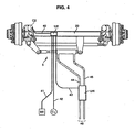
- FIG. figure 4 The diagram of the steering device of the steering wheels of the trailer 2 is illustrated in FIG. figure 4 , namely those associated with the axle 20.
- the sensor C 1 which delivers a signal representative of the steering angle of the wheels of the tractor, is connected, via a line 42, to an electronic unit UE installed on the steering axle 20.
- the electronic unit UE is connected and is able to control a hydraulic control unit UH which, itself, is connected to the hydraulic circuit of the tractor by lines 46.
- This unit UH controls, through hydraulic lines 44 and 45, a steering cylinder 5 which directs the steering wheels of the axle 20 through a conventional steering linkage.
- the device of the invention also comprises a control sensor which delivers to the electronic unit UE a signal value representative of the position of the steering wheels of the trailer 2.
- This sensor referenced C 2
- This sensor which is housed inside the pivot of one of the wheels that team the axle.
- This sensor which is also preferably a Hall effect potentiometer, is connected to the electronic unit UE by a line 40.
- this electronic unit is connected by a line 41 to an embedded box BE.
- This housing is intended to be moved close to the driver of the tractor, especially in his cabin.
- the electronic unit UE contains a printed circuit associated with a microcontroller for controlling the axle 20, as a function of the information transmitted by the two sensors.
- the BE housing it is advantageously provided with a three-position switch, one for a learning mode, the second for a control mode and the third for a "straight line" mode.
- the electronic unit UE thus integrates means that will allow the system, in a first step, to function by learning.
- the sensor C 1 associated with the linkage 3 installed on the drawbar 24, and the potentiometer C 2 installed in the axle 20 allow the measurement of the two angles, namely that formed by the respective longitudinal axes of the tractor and of the trailer and ⁇ , both of which are translated as electrical signals.
- a first step the user starts the device, then uses the onboard box BE to switch it to a learning position.
- the hydraulic supply of the jack 5 is then free.
- the wheels of the axle 20 can then evolve and move freely.
- the second step is then to place the tractor 1 and its trailer 2 in a straight line.
- the user presses a push button which is equipped with the housing BE.
- This causes the UE to take measurements of the two signals recorded for each of the two potentiometers C 1 and C 2 . It assigns these signals the value zero.
- a light provided on the BE box then starts to flash to indicate that both measurements have been recorded.
- the user positions the trailer in the maximum steering position of the axle 10 of the tractor.
- the indicator light of the housing can come on for a few seconds.
- pressing the push button again will memorize the two maximum values measured by the two sensors.
- the learning phase is then complete.
- the curve relating to the sensor C 1 ( figure 5 ) will define during the regulation phase of the trailer what angle to apply to the axle 20 of the trailer to follow the best trajectory.
- the second curve ( figure 6 ), drawn with the two measurements taken on the axle 20 by the sensor C 2 , will allow to correct the movement of this axle if it does not correspond to the desired angle value.
- the system can control the gyration of the axle 20, according to the two stored curves.
- the user can then open the hydraulic supply of the unit UH to control the axle 20. To do this, he switches the switch of the onboard box UE in the regulation position.
- the present device makes it possible to use the convoy in four different situations.
- the user cuts the hydraulic power supply UH and also cuts off the power supply of the electronic unit.
- the wheels of the axle of the trailer 2 are then in the "free follower" position. They will therefore freely follow the movement of the tractor, including curves.
- the electronic unit if it detects an error, for example due to the tearing of a cable, controls the axle 20 in the "locked" position.
- a third situation corresponds to a failure of the hydraulic power supply and the power supply of the electronic unit. This corresponds to the learning phase of the system, as just described above.
- a fourth situation corresponds to the supply of the circuit and the power supply of the electronic unit. This is the actual phase of use of the system. The user can then start if he wants to keep the previously saved usage settings.
- the hydraulic control is by proportional hydraulic distributors, which have the advantage of being flexible and precise.
- the handling of the jack 5 is managed by applying a coefficient that takes into account the section variations of its rod, so that it has no difference in reactivity, regardless of the direction of movement of said rod.
Landscapes
- Engineering & Computer Science (AREA)
- Chemical & Material Sciences (AREA)
- Combustion & Propulsion (AREA)
- Transportation (AREA)
- Mechanical Engineering (AREA)
- Steering Control In Accordance With Driving Conditions (AREA)
- Steering Controls (AREA)
- Platform Screen Doors And Railroad Systems (AREA)
- Regulating Braking Force (AREA)
- Steering-Linkage Mechanisms And Four-Wheel Steering (AREA)
Claims (9)
- Verfahren zum Steuern der Leiträder (200, 220) eines Anhängers (2), der durch ein Gelenk (13) mit einem Zugfahrzeug (1) verbunden ist, welches umfasst:- wenigstens ein Mittel zum hydraulischen Anschließen des Anhängers (2) an einen unter Druck stehenden Hydraulikkreis des Zugfahrzeugs,- einen Lenkmechanismus, der die Leiträder des Anhängers durch wenigstens ein Hydraulikventil über eine Hydrauliksteuereinheit (UH) beeinflusst, die mit dem Anschlussmittel verbunden ist;- eine Elektronikeinheit (UE) zum Steuern der Hydrauliksteuereinheit (UH) in Abhängigkeit von von Sensoren (C1, C2) bereitgestellten Signalen;- wenigstens einen Winkelsensor (C1), der der Elektronikeinheit (UE) einen Signalwert bereitstellt, der den von der jeweiligen Längsachse (12, 23) des Zugfahrzeugs (1) und des Anhängers (2) gebildeten Winkel angibt;- einen Kontrollsensor (C2), der der Elektronikeinheit (UE) einen Signalwert liefert, der die Position der Leiträder (200, 220) des Anhängers (2) angibt;dadurch gekennzeichnet, dass es darin besteht, die folgenden Schritte umzusetzen:a) in einem ersten Modus, genannt - Lernmodus -, in dem die Hydraulikversorgung des Anhängers (2) unterbrochen ist:- Messen und Speichern der von den Sensoren (C1, C2) bereitgestellten Signale einerseits, wenn das Fahrzeug (1) und Anhänger (2) in einer Linie ausgerichtet sind und andererseits, wenn das Fahrzeug (1) in maximaler Lenkeinschlagposition bezüglich des Anhängers (2) ist;- aus diesen Signalen, Ermitteln für jeden Sensor des Relationswerts des Signals = f (Winkel);b) dann in einem zweiten Modus, genannt - Regulierungsmodus -, in dem die Hydraulikversorgung des Anhängers (2) wiederhergestellt ist:- regelmäßiges Vergleichen der Werte der von den Sensoren (C1, C2) bereitgestellten Signale und im Fall, in dem sie verschieden sind, Zuweisen desselben Werts wie der des Winkelsensors (C1) dem Kontrollsensor (C2), um diesen Winkel unter Berücksichtigung der Relation zu korrigieren und Steuern der Hydrauliksteuereinheit (UH) im Hinblick darauf, die Ausrichtung der Leiträder (200, 220) des Anhängers (2) zu verändern.
- Verfahren gemäß Anspruch 1, dadurch gekennzeichnet, dass eine Hydrauliksteuereinheit (UH) verwendet wird, die proportionale Hydraulikverteiler umfasst.
- Vorrichtung zum Steuern der Leiträder (200, 220) eines Anhängers, der durch ein Gelenk (13) mit einem Zugfahrzeug (1) verbunden ist, für die Umsetzung des Verfahrens gemäß Anspruch 1 oder 2, wobei diese Vorrichtung umfasst:- wenigstens ein Mittel zum hydraulischen Anschließen des Anhängers (2) an einen unter Druck stehenden Hydraulikkreis des Zugfahrzeugs,- einen Lenkmechanismus, der die Leiträder des Anhängers durch wenigstens ein Hydraulikventil über eine Hydrauliksteuereinheit (UH) beeinflusst, die mit dem Verbindungsmittel verbunden ist;- eine Elektronikeinheit (UE) zum Steuern der Hydrauliksteuereinheit in Abhängigkeit von von Sensoren (C1, C2) bereitgestellten Signalen;- wenigstens einen Winkelsensor (C1), der der Elektronikeinheit (UE) einen Signalwert bereitstellt, der den von der jeweiligen Längsachse (12, 23) des Zugfahrzeugs (1) und des Anhängers (2) gebildeten Winkel angibt;- einen Kontrollsensor (C2), der der Elektronikeinheit (UE) einen Signalwert liefert, der die Position der Leiträder (200, 220) des Anhängers (2) angibt,dadurch gekennzeichnet, dass die Elektronikeinheit (UE) Mittel einbezieht:a) in einem ersten Modus, genannt - Lernmodus -, in dem die Hydraulikversorgung des Anhängers (2) unterbrochen ist:- zum Messen und Speichern der von den Sensoren (C1, C2) bereitgestellten Signale einerseits, wenn das Fahrzeug (1) und Anhänger (2) in einer Linie ausgerichtet sind und andererseits, wenn das Fahrzeug (4) in maximaler Lenkeinschlagposition bezüglich des Anhängers (2) ist;- zum Ermitteln aus diesen Signalen und für jeden Sensor des Relationswerts des Signals = f (Winkel);b) in einem zweiten Modus, genannt - Regulierungsmodus -, in dem die Hydraulikversorgung des Anhängers (2) wiederhergestellt ist:- zum regelmäßigen Vergleichen der Werte der Signale, die von den Sensoren (C1, C2) bereitgestellt werden, und im Fall, in dem sie verschieden sind, Zuweisen desselben Werts wie der des Winkelsensors (C1) dem Kontrollsensor (C2) zum Korrigieren dieses Winkels unter Berücksichtigung der Relation und Steuern der Hydrauliksteuereinheit im Hinblick darauf, die Ausrichtung der Leiträder (200, 220) des Anhängers (2) zu verändern.
- Vorrichtung gemäß Anspruch 3, dadurch gekennzeichnet, dass die Sensoren (C1, C2) Halleffektpotentiometer sind.
- Vorrichtung gemäß Anspruch 3 oder 4, dadurch gekennzeichnet, dass der Winkelsensor (C1) auf einer fest mit dem Anhänger (2) verbundenen Deichsel (24) zur Gelenkverbindung mit dem Zugfahrzeug (1) befestigt ist und über eine deformierbare Parallelogrammgelenkverbindung (3) mit dem Fahrzeug verbunden ist,
- Vorrichtung gemäß einem der Ansprüche 3 bis 5, dadurch gekennzeichnet, dass der Kontrollsensor (C2) im Drehzapfen der Radachse (20) der Leiträder (200, 220) des Anhängers (2) montiert ist.
- Vorrichtung gemäß einem der Ansprüche 3 bis 6, dadurch gekennzeichnet, dass sie ein Gehäuse (BE) umfasst, das von dem Zugfahrzeug (1) getragen wird, das seinem Fahrer zur Verfügung steht, und das mit der Elektronikeinheit (UE) verbunden ist, wobei dieses Gehäuse (BE) Mittel zum Umschalten vom Lernmodus in den Regulierungsmodus und umgekehrt umfasst, sowie Mittel zur Bestätigung der Messungen der im Lernzustand gelesenen Signale.
- Vorrichtung gemäß einem der Ansprüche 3 bis 7, dadurch gekennzeichnet, dass die Hydrauliksteuervorrichtung (UH) proportionale Hydraulikverteiler umfasst.
- Vorrichtung gemäß einem der Ansprüche 3 bis 8, dadurch gekennzeichnet, dass die Elektronikeinheit (UE) Mittel einbezieht, die geeignet sind im Fall der Detektierung eines Fehlers, die Ausrichtung der blockierten Leiträder (200, 220) in gerade Position, das heißt parallel zur Längsachse (23) des Anhängers (2), zu steuern.
Applications Claiming Priority (1)
| Application Number | Priority Date | Filing Date | Title |
|---|---|---|---|
| FR0610682A FR2909632B1 (fr) | 2006-12-07 | 2006-12-07 | Procede et dispositif de commande des roues directrices d'une remorque. |
Publications (2)
| Publication Number | Publication Date |
|---|---|
| EP1932747A1 EP1932747A1 (de) | 2008-06-18 |
| EP1932747B1 true EP1932747B1 (de) | 2010-02-24 |
Family
ID=38144866
Family Applications (1)
| Application Number | Title | Priority Date | Filing Date |
|---|---|---|---|
| EP07122500A Not-in-force EP1932747B1 (de) | 2006-12-07 | 2007-12-06 | Verfahren und Vorrichtung zur Lenkung der Leiträder eines Anhängers |
Country Status (5)
| Country | Link |
|---|---|
| EP (1) | EP1932747B1 (de) |
| AT (1) | ATE458661T1 (de) |
| DE (1) | DE602007004929D1 (de) |
| ES (1) | ES2340960T3 (de) |
| FR (1) | FR2909632B1 (de) |
Families Citing this family (4)
| Publication number | Priority date | Publication date | Assignee | Title |
|---|---|---|---|---|
| AT507594B1 (de) * | 2008-11-26 | 2011-03-15 | Josef Ing Scharmueller | Zwangslenkung |
| FR2967636B1 (fr) * | 2010-11-19 | 2013-06-07 | Envision Vehicle Engineering Novasio Technology Event | Dispositif de commande rotative d'un essieu directeur de remorque et remorque comportant un tel dispositif |
| DE202011003521U1 (de) * | 2011-03-05 | 2011-06-09 | Zunhammer, Sebastian, Dipl.-Ing. (FH), 83301 | Zugfahrzeug mit Fahrzeuganhänger |
| EP4446201A1 (de) | 2023-04-11 | 2024-10-16 | Etablissements Deves | Selbstlenkender selbstlenkender achsanhänger |
Family Cites Families (4)
| Publication number | Priority date | Publication date | Assignee | Title |
|---|---|---|---|---|
| JPS62289472A (ja) * | 1986-06-09 | 1987-12-16 | Nippon Spindle Mfg Co Ltd | トラクタに牽引されるトレ−ラのステアリング制御方法およびその装置 |
| FR2611635B1 (fr) * | 1987-02-27 | 1991-03-15 | Billig Sarl Ets | Dispositif de commande de roues directrices d'une remorque, et remorque equipee d'un tel dispositif |
| JP2662970B2 (ja) * | 1988-03-02 | 1997-10-15 | 生物系特定産業技術研究推進機構 | 農用牽引式作業機の操向操作方法 |
| JP3719097B2 (ja) * | 2000-04-19 | 2005-11-24 | 東洋農機株式会社 | 牽引式作業機の車輪操舵装置 |
-
2006
- 2006-12-07 FR FR0610682A patent/FR2909632B1/fr not_active Expired - Fee Related
-
2007
- 2007-12-06 ES ES07122500T patent/ES2340960T3/es active Active
- 2007-12-06 DE DE602007004929T patent/DE602007004929D1/de active Active
- 2007-12-06 EP EP07122500A patent/EP1932747B1/de not_active Not-in-force
- 2007-12-06 AT AT07122500T patent/ATE458661T1/de not_active IP Right Cessation
Also Published As
| Publication number | Publication date |
|---|---|
| ATE458661T1 (de) | 2010-03-15 |
| EP1932747A1 (de) | 2008-06-18 |
| DE602007004929D1 (de) | 2010-04-08 |
| ES2340960T3 (es) | 2010-06-11 |
| FR2909632B1 (fr) | 2009-02-13 |
| FR2909632A1 (fr) | 2008-06-13 |
Similar Documents
| Publication | Publication Date | Title |
|---|---|---|
| EP0168411B1 (de) | Steuereinrichtung für flugzeuglenkung | |
| FR2772331A1 (fr) | Direction pour un vehicule | |
| FR2559117A1 (fr) | Systeme de direction pour vehicules prenant en compte les effets d'une perturbation exterieure | |
| EP1932747B1 (de) | Verfahren und Vorrichtung zur Lenkung der Leiträder eines Anhängers | |
| EP1316490B1 (de) | Elektrische Lenkung für Fahrzeuge | |
| FR2553365A1 (fr) | Systeme de direction pour vehicules a quatre roues directrices dans lequel le rapport des angles de braquages des roues avant et arriere est modere en cas de brusque variation de la vitesse du vehicule | |
| EP0282426B1 (de) | Steuervorrichtung für die Lenkräder eines Anhängers und Anhänger mit einer solchen Vorrichtung | |
| EP0383688B1 (de) | Vorrichtung zum Detektieren des geschalteten Ganges eines Handschaltgetriebes, gekoppelt mit einem Schaltmechanismus für eine automatische Kupplung | |
| DE10156723A1 (de) | Luftdruckerfassungsvorrichtung für ein Rad | |
| EP2181031A2 (de) | Servolenkvorrichtung für automobile | |
| EP0556082B1 (de) | Hydraulische Servolenkung mit Servo-Rückstellvorrichtung und Hilfsantrieb | |
| EP0379430B1 (de) | Lenkvorrichtung für mindestens einen Radsatz eines Fahrzeuges | |
| FR2851539A1 (fr) | Palier d'articulation d'un element de direction | |
| FR2597055A1 (fr) | Dispositif de freinage et de freinage de braquage pour vehicules tout terrain | |
| EP0551471B1 (de) | SPIELFAHRZEUGE MIT LENKBAREN RäDER | |
| FR3144963A1 (fr) | ensemble de direction pour véhicule automobile | |
| EP0703389B1 (de) | Gangwechsel-Steuerungsverfahren und Vorrichtung bei einem mechanischen Stufengetriebe für Fahrzeug mit elektrohydraulischer Kupplung | |
| EP1655205B1 (de) | System und Verfahren zur Lenkhilfe für die lenkbaren Räder eines Kraftfahrzeugs | |
| EP1599375B1 (de) | Verfahren zur richtungssteuerung eines kraftfahrzeugs | |
| FR2666295A1 (fr) | Dispositif pour le controle de l'alignement des roues directrices d'une semi-remorque ou d'une remorque. | |
| FR2712766A1 (fr) | Procédé et dispositif de contrôle en effort et en position. | |
| WO2006070155A1 (fr) | Systeme d'actionnement d'arbre de direction instrumente comprenant un centre fixe | |
| EP1234747A1 (de) | Elektrische Servolenkung für ein Fahrzeug und Regelverfahren dafür | |
| DE10156724A1 (de) | Luftdruckerfassungsvorrichtung für ein Rad | |
| FR2908722A1 (fr) | Systeme de direction pour vehicule automobile. |
Legal Events
| Date | Code | Title | Description |
|---|---|---|---|
| PUAI | Public reference made under article 153(3) epc to a published international application that has entered the european phase |
Free format text: ORIGINAL CODE: 0009012 |
|
| AK | Designated contracting states |
Kind code of ref document: A1 Designated state(s): AT BE BG CH CY CZ DE DK EE ES FI FR GB GR HU IE IS IT LI LT LU LV MC MT NL PL PT RO SE SI SK TR |
|
| AX | Request for extension of the european patent |
Extension state: AL BA HR MK RS |
|
| 17P | Request for examination filed |
Effective date: 20081030 |
|
| AKX | Designation fees paid |
Designated state(s): AT BE BG CH CY CZ DE DK EE ES FI FR GB GR HU IE IS IT LI LT LU LV MC MT NL PL PT RO SE SI SK TR |
|
| GRAP | Despatch of communication of intention to grant a patent |
Free format text: ORIGINAL CODE: EPIDOSNIGR1 |
|
| GRAC | Information related to communication of intention to grant a patent modified |
Free format text: ORIGINAL CODE: EPIDOSCIGR1 |
|
| GRAS | Grant fee paid |
Free format text: ORIGINAL CODE: EPIDOSNIGR3 |
|
| GRAA | (expected) grant |
Free format text: ORIGINAL CODE: 0009210 |
|
| AK | Designated contracting states |
Kind code of ref document: B1 Designated state(s): AT BE BG CH CY CZ DE DK EE ES FI FR GB GR HU IE IS IT LI LT LU LV MC MT NL PL PT RO SE SI SK TR |
|
| REG | Reference to a national code |
Ref country code: GB Ref legal event code: FG4D Free format text: NOT ENGLISH |
|
| REG | Reference to a national code |
Ref country code: CH Ref legal event code: EP |
|
| REG | Reference to a national code |
Ref country code: IE Ref legal event code: FG4D Free format text: LANGUAGE OF EP DOCUMENT: FRENCH |
|
| REF | Corresponds to: |
Ref document number: 602007004929 Country of ref document: DE Date of ref document: 20100408 Kind code of ref document: P |
|
| REG | Reference to a national code |
Ref country code: CH Ref legal event code: NV Representative=s name: MICHELI & CIE SA |
|
| REG | Reference to a national code |
Ref country code: ES Ref legal event code: FG2A Ref document number: 2340960 Country of ref document: ES Kind code of ref document: T3 |
|
| REG | Reference to a national code |
Ref country code: NL Ref legal event code: VDEP Effective date: 20100224 |
|
| LTIE | Lt: invalidation of european patent or patent extension |
Effective date: 20100224 |
|
| PG25 | Lapsed in a contracting state [announced via postgrant information from national office to epo] |
Ref country code: LT Free format text: LAPSE BECAUSE OF FAILURE TO SUBMIT A TRANSLATION OF THE DESCRIPTION OR TO PAY THE FEE WITHIN THE PRESCRIBED TIME-LIMIT Effective date: 20100224 Ref country code: IS Free format text: LAPSE BECAUSE OF FAILURE TO SUBMIT A TRANSLATION OF THE DESCRIPTION OR TO PAY THE FEE WITHIN THE PRESCRIBED TIME-LIMIT Effective date: 20100624 Ref country code: PT Free format text: LAPSE BECAUSE OF FAILURE TO SUBMIT A TRANSLATION OF THE DESCRIPTION OR TO PAY THE FEE WITHIN THE PRESCRIBED TIME-LIMIT Effective date: 20100625 |
|
| PG25 | Lapsed in a contracting state [announced via postgrant information from national office to epo] |
Ref country code: SI Free format text: LAPSE BECAUSE OF FAILURE TO SUBMIT A TRANSLATION OF THE DESCRIPTION OR TO PAY THE FEE WITHIN THE PRESCRIBED TIME-LIMIT Effective date: 20100224 Ref country code: PL Free format text: LAPSE BECAUSE OF FAILURE TO SUBMIT A TRANSLATION OF THE DESCRIPTION OR TO PAY THE FEE WITHIN THE PRESCRIBED TIME-LIMIT Effective date: 20100224 Ref country code: LV Free format text: LAPSE BECAUSE OF FAILURE TO SUBMIT A TRANSLATION OF THE DESCRIPTION OR TO PAY THE FEE WITHIN THE PRESCRIBED TIME-LIMIT Effective date: 20100224 Ref country code: FI Free format text: LAPSE BECAUSE OF FAILURE TO SUBMIT A TRANSLATION OF THE DESCRIPTION OR TO PAY THE FEE WITHIN THE PRESCRIBED TIME-LIMIT Effective date: 20100224 Ref country code: AT Free format text: LAPSE BECAUSE OF FAILURE TO SUBMIT A TRANSLATION OF THE DESCRIPTION OR TO PAY THE FEE WITHIN THE PRESCRIBED TIME-LIMIT Effective date: 20100224 |
|
| REG | Reference to a national code |
Ref country code: IE Ref legal event code: FD4D |
|
| PG25 | Lapsed in a contracting state [announced via postgrant information from national office to epo] |
Ref country code: SE Free format text: LAPSE BECAUSE OF FAILURE TO SUBMIT A TRANSLATION OF THE DESCRIPTION OR TO PAY THE FEE WITHIN THE PRESCRIBED TIME-LIMIT Effective date: 20100224 Ref country code: RO Free format text: LAPSE BECAUSE OF FAILURE TO SUBMIT A TRANSLATION OF THE DESCRIPTION OR TO PAY THE FEE WITHIN THE PRESCRIBED TIME-LIMIT Effective date: 20100224 Ref country code: IE Free format text: LAPSE BECAUSE OF FAILURE TO SUBMIT A TRANSLATION OF THE DESCRIPTION OR TO PAY THE FEE WITHIN THE PRESCRIBED TIME-LIMIT Effective date: 20100224 Ref country code: NL Free format text: LAPSE BECAUSE OF FAILURE TO SUBMIT A TRANSLATION OF THE DESCRIPTION OR TO PAY THE FEE WITHIN THE PRESCRIBED TIME-LIMIT Effective date: 20100224 Ref country code: EE Free format text: LAPSE BECAUSE OF FAILURE TO SUBMIT A TRANSLATION OF THE DESCRIPTION OR TO PAY THE FEE WITHIN THE PRESCRIBED TIME-LIMIT Effective date: 20100224 Ref country code: GR Free format text: LAPSE BECAUSE OF FAILURE TO SUBMIT A TRANSLATION OF THE DESCRIPTION OR TO PAY THE FEE WITHIN THE PRESCRIBED TIME-LIMIT Effective date: 20100525 Ref country code: CY Free format text: LAPSE BECAUSE OF FAILURE TO SUBMIT A TRANSLATION OF THE DESCRIPTION OR TO PAY THE FEE WITHIN THE PRESCRIBED TIME-LIMIT Effective date: 20100224 |
|
| PG25 | Lapsed in a contracting state [announced via postgrant information from national office to epo] |
Ref country code: BG Free format text: LAPSE BECAUSE OF FAILURE TO SUBMIT A TRANSLATION OF THE DESCRIPTION OR TO PAY THE FEE WITHIN THE PRESCRIBED TIME-LIMIT Effective date: 20100524 Ref country code: CZ Free format text: LAPSE BECAUSE OF FAILURE TO SUBMIT A TRANSLATION OF THE DESCRIPTION OR TO PAY THE FEE WITHIN THE PRESCRIBED TIME-LIMIT Effective date: 20100224 Ref country code: SK Free format text: LAPSE BECAUSE OF FAILURE TO SUBMIT A TRANSLATION OF THE DESCRIPTION OR TO PAY THE FEE WITHIN THE PRESCRIBED TIME-LIMIT Effective date: 20100224 |
|
| PLBE | No opposition filed within time limit |
Free format text: ORIGINAL CODE: 0009261 |
|
| STAA | Information on the status of an ep patent application or granted ep patent |
Free format text: STATUS: NO OPPOSITION FILED WITHIN TIME LIMIT |
|
| PG25 | Lapsed in a contracting state [announced via postgrant information from national office to epo] |
Ref country code: DK Free format text: LAPSE BECAUSE OF FAILURE TO SUBMIT A TRANSLATION OF THE DESCRIPTION OR TO PAY THE FEE WITHIN THE PRESCRIBED TIME-LIMIT Effective date: 20100224 |
|
| 26N | No opposition filed |
Effective date: 20101125 |
|
| PG25 | Lapsed in a contracting state [announced via postgrant information from national office to epo] |
Ref country code: IT Free format text: LAPSE BECAUSE OF FAILURE TO SUBMIT A TRANSLATION OF THE DESCRIPTION OR TO PAY THE FEE WITHIN THE PRESCRIBED TIME-LIMIT Effective date: 20100224 |
|
| PG25 | Lapsed in a contracting state [announced via postgrant information from national office to epo] |
Ref country code: MC Free format text: LAPSE BECAUSE OF NON-PAYMENT OF DUE FEES Effective date: 20101231 |
|
| PG25 | Lapsed in a contracting state [announced via postgrant information from national office to epo] |
Ref country code: MT Free format text: LAPSE BECAUSE OF FAILURE TO SUBMIT A TRANSLATION OF THE DESCRIPTION OR TO PAY THE FEE WITHIN THE PRESCRIBED TIME-LIMIT Effective date: 20100224 |
|
| PG25 | Lapsed in a contracting state [announced via postgrant information from national office to epo] |
Ref country code: LU Free format text: LAPSE BECAUSE OF NON-PAYMENT OF DUE FEES Effective date: 20101206 Ref country code: HU Free format text: LAPSE BECAUSE OF FAILURE TO SUBMIT A TRANSLATION OF THE DESCRIPTION OR TO PAY THE FEE WITHIN THE PRESCRIBED TIME-LIMIT Effective date: 20100825 |
|
| PG25 | Lapsed in a contracting state [announced via postgrant information from national office to epo] |
Ref country code: TR Free format text: LAPSE BECAUSE OF FAILURE TO SUBMIT A TRANSLATION OF THE DESCRIPTION OR TO PAY THE FEE WITHIN THE PRESCRIBED TIME-LIMIT Effective date: 20100224 |
|
| REG | Reference to a national code |
Ref country code: FR Ref legal event code: PLFP Year of fee payment: 9 |
|
| REG | Reference to a national code |
Ref country code: FR Ref legal event code: PLFP Year of fee payment: 10 |
|
| REG | Reference to a national code |
Ref country code: FR Ref legal event code: PLFP Year of fee payment: 11 |
|
| PGFP | Annual fee paid to national office [announced via postgrant information from national office to epo] |
Ref country code: FR Payment date: 20171213 Year of fee payment: 11 |
|
| PGFP | Annual fee paid to national office [announced via postgrant information from national office to epo] |
Ref country code: BE Payment date: 20171229 Year of fee payment: 11 |
|
| PGFP | Annual fee paid to national office [announced via postgrant information from national office to epo] |
Ref country code: ES Payment date: 20180220 Year of fee payment: 11 Ref country code: GB Payment date: 20180117 Year of fee payment: 11 Ref country code: DE Payment date: 20180111 Year of fee payment: 11 Ref country code: CH Payment date: 20180123 Year of fee payment: 11 |
|
| REG | Reference to a national code |
Ref country code: DE Ref legal event code: R119 Ref document number: 602007004929 Country of ref document: DE |
|
| REG | Reference to a national code |
Ref country code: CH Ref legal event code: PL |
|
| GBPC | Gb: european patent ceased through non-payment of renewal fee |
Effective date: 20181206 |
|
| REG | Reference to a national code |
Ref country code: BE Ref legal event code: MM Effective date: 20181231 |
|
| PG25 | Lapsed in a contracting state [announced via postgrant information from national office to epo] |
Ref country code: FR Free format text: LAPSE BECAUSE OF NON-PAYMENT OF DUE FEES Effective date: 20181231 Ref country code: DE Free format text: LAPSE BECAUSE OF NON-PAYMENT OF DUE FEES Effective date: 20190702 |
|
| PG25 | Lapsed in a contracting state [announced via postgrant information from national office to epo] |
Ref country code: BE Free format text: LAPSE BECAUSE OF NON-PAYMENT OF DUE FEES Effective date: 20181231 |
|
| PG25 | Lapsed in a contracting state [announced via postgrant information from national office to epo] |
Ref country code: GB Free format text: LAPSE BECAUSE OF NON-PAYMENT OF DUE FEES Effective date: 20181206 Ref country code: LI Free format text: LAPSE BECAUSE OF NON-PAYMENT OF DUE FEES Effective date: 20181231 Ref country code: CH Free format text: LAPSE BECAUSE OF NON-PAYMENT OF DUE FEES Effective date: 20181231 |
|
| REG | Reference to a national code |
Ref country code: ES Ref legal event code: FD2A Effective date: 20200131 |
|
| PG25 | Lapsed in a contracting state [announced via postgrant information from national office to epo] |
Ref country code: ES Free format text: LAPSE BECAUSE OF NON-PAYMENT OF DUE FEES Effective date: 20181207 |